Table of Contents
Advertisement
Quick Links
Transition Networks
SM24DPB Quick Start Guide
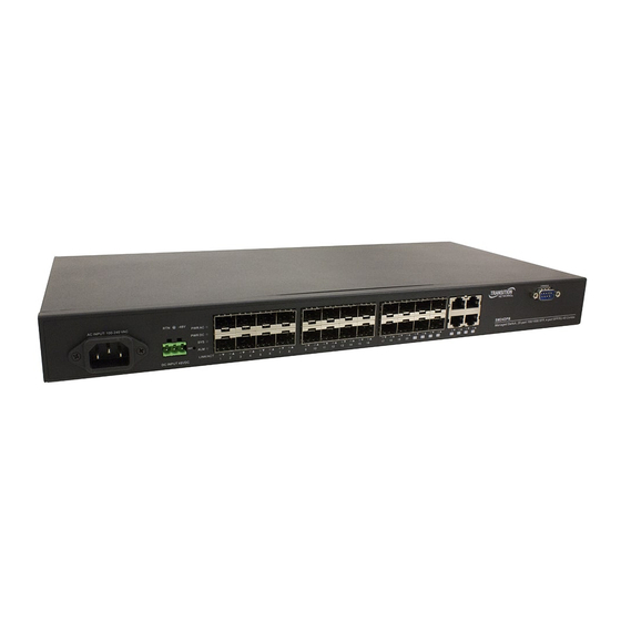
SM24DPB
(20) 100/1000Base-X SFP Ports + (4) 100/1000Base-X
SFP/RJ-45 Combo Ports
Quick Start Guide
Safety Warnings and Cautions
See the Install Guide for important Safety Warnings and Cautions, Compliance, and Safety Statements.
See the Install Guide for Network Planning, Selecting a Site, Ethernet Cabling, Mounting, Installing an SFP,
and Connecting to a Power Source. The SM24DPB provides 20 GbE SFP ports, 4 Combo GbE RJ45/SFP ports and a DB9
Console port, with built-in AC and DC dual power supplies. Note: Make all cable connections before connecting Power.
Front Panel
The switch has 10/100/1000BASE-T RJ-45 ports. All RJ-45 ports
1000BASE-T Ports:
support automatic MDI/MDI-X operation, auto-negotiation and IEEE 802.3x auto-
negotiation of flow control, so the best data rate and transmission are set automatically.
The switch supports SFP transceiver slots port 1 to port 24, ports
SFP Transceiver Slots:
21 to 24 are shared with RJ-45 (ports 21-24 are combo interface RJ45/SFP). For
information on the recommended standards for fiber optic cabling, see the Install Guide. See the Transition Networks
SFP webpage
for all related information on Transition Networks SFPs.
The SM24DPB switch includes system and
System Status and Port LEDs:
port LEDs that simplify installation and troubleshooting. The LEDs are located
on left hand side of the front panel. See the Install Guide for details.
There are dual power inputs on the front for power
Power Supply Sockets:
redundancy. The switch has a 100~240 VAC power socket for AC power Input
and a positive or negative 24-72VDC power input via the terminal block.
Ethernet Cabling
To ensure proper operation when installing the switch into a network, make sure that the current cables are suitable
for 100BASE-TX or 1000BASE-T operation.
Switch
Label side top
of SFP module
Bale
Triangle
Clasp
indicates bottom
of SFP cage
SFP Module
RJ-45 Connection
SFP Transceiver
Power Connection
Warning: Connect the power supply to the switch first, then connect the power supply to power.
Otherwise catastrophic product failure may occur. 1. Verify that power is off to the DC circuit that you are going to attach
to the switch DC-input connector. This can be either of the two power supplies (AC-input or DC-input) or site source DC.
2. Added precaution: place an appropriate safety flag and lockout device at the source power circuit breaker or place a
piece of adhesive tape over the circuit breaker handle to prevent accidental power restoration while you are working on
the circuit. Power Disconnection: To disconnect switch power after a successfully boot: 1. Turn off power to the switch.
2. Disconnect the cables.
33680 Rev. B
https://www.transition.com
Page 1 of 2
Advertisement
Table of Contents

Subscribe to Our Youtube Channel
Related Manuals for Transition Networks SM24DPB


Summary of Contents for Transition Networks SM24DPB
- Page 1 See the Install Guide for Network Planning, Selecting a Site, Ethernet Cabling, Mounting, Installing an SFP, and Connecting to a Power Source. The SM24DPB provides 20 GbE SFP ports, 4 Combo GbE RJ45/SFP ports and a DB9 Console port, with built-in AC and DC dual power supplies. Note: Make all cable connections before connecting Power.
- Page 2 (33682), and (33683). For Transition Networks Manuals go to the Product Support webpage (no logon required). Transition Networks * 10900 Red Circle Drive * Minnetonka, MN 55343 * tel: +1.952.941.7600 | toll free: 1.800.526.9267 | fax: 952.941.2322 | sales@transition.com techsupport@transition.com customerservice@transition.com Copyright©...
Need help?
Do you have a question about the SM24DPB and is the answer not in the manual?
Questions and answers