
Related Manuals for Transition Networks SM24DPa


Summary of Contents for Transition Networks SM24DPa
-
Page 1: User Guide
SM24DPA 16-Port 100/1000 SFP plus 8 RJ-45/100/1000 SFP Combo Port Managed Switch User Guide Rev.A0 19-Mar-11... - Page 3 For prompt response when calling for service information, have the following information ready: - Product serial number and revision - Date of purchase - Vendor or place of purchase You can reach Transition Networks technical support at: E-mail: techsupport@transition.com Transition Networks 10900 Red Circle Drive Minnetonka, MN 55344 United States of America Telephone: +1.800.526.9267...
-
Page 4: Table Of Contents
2-1-4. Configuring the Management Agent of SM24DPA ........... 16 2-1-4-1. Configuring the Management Agent of SM24DPA through the Serial RS-232 Port16 2-1-4-2. Configuring the Management Agent of SM24DPA through the Ethernet Port ..18 2-1-5. IP Address Assignment ..................20 2-2. - Page 5 3-4-2. Static Filter ....................... 74 3-4-3. Static Forward ....................75 3-4-4. MAC Alias ......................76 3-4-5. MAC Table......................77 3-5. GVRP........................78 3-5-1. Config ....................... 78 3-5-2. Counter......................81 3-5-3. Group........................ 83 3-6. Q ............84 UALITY OF ERVICE ONFIGURATION 3-6-1.
- Page 6 3-16-9. MVR Group Membership................200 3-17. A ..................201 LARM ONFIGURATION 3-17-1. Events ......................202 3-17-2. Email ......................203 3-18. DHCP S ....................204 NOOPING 3-18-1. DHCP Snooping State ...................204 3-18-2. DHCP Snooping Entry ..................205 3-18-3. DHCP Snooping Client .................206 3-19. LLDP ........................207 3-19-1. LLDP State ....................207 3-19-2.
-
Page 7: Revision History
Revision History Date Revision 03/01/2011 Rev.A0 1-Mar-11... - Page 8 Warning: Self-demolition on Product is strictly prohibited. Damage caused by self- demolition will be charged for repairing fees. Do not place product at outdoor or sandstorm. Before installation, please make sure input power supply and product specifications are compatible to each other. ...
- Page 9 In this user manual, it will not only tell you how to install and connect your network system but also how to configure and monitor the SM24DPA through the built-in CLI through RS-232 serial interface and Web GUI. The hardware and software functions are shown as well as the examples of the operation for web- based interface and command-line interface (CLI).
-
Page 10: Introduction
1. Introduction 1-1. Overview of SM24DPA SM24DPA, a 24-port all Fiber Managed Switch, is a standard switch that meets all IEEE 802.3/u/x/z Gigabit, Fast Ethernet specifications. 16-Port (100/1000) Dual Speed SFP and 8-Port Combo Gigabit RJ-45/ (100/1000) SFP management Ethernet switch. The switch can be managed through RS-232 serial port via directly connection, or through Ethernet port using CLI or Web-based management unit, associated with SNMP agent. - Page 11 • Key Features in the Device QoS: Support Quality of Service by the IEEE 802.1P standard. There are two priority queue and packet transmission schedule. Spanning Tree: Support IEEE 802.1D, IEEE 802.1w (RSTP: Rapid Spanning Tree Protocol) standards. VLAN: Support Port-based VLAN and IEEE802.1Q Tag VLAN. Support VLAN ID 1~4094.
- Page 12 with the router on its upstream interface through the exchange of IGMP messages. However, when acting as the proxy, the system performs the host portion of the IGMP task on the upstream interface as follows: When queried, sends group membership reports to the group.
-
Page 13: Checklist
1-2. Checklist Before you start installing the switch, verify that the package contains the following: SM24DPA 16-Port 100/1000 Dual Speed SFP + 8-Port RJ-45/(100/1000M SFP) Managed Switch Mounting Accessory (for 19” Rack Shelf) The User's Manual in CD-ROM ... - Page 14 Hardware • 16 (100/1000) SFP Fiber ports • 8 10/100/1000Mbps TP or (100/1000) SFP Fiber dual media auto sense • SM24DPA supports AC Power Input • 1392KB on-chip frame buffer • Support jumbo frame up to 9K bytes • Programmable classifier for QoS (Layer 4/Multimedia) •...
- Page 15 • Supports multiple spanning tree (802.1s MSTP) • Supports SSL/SSH supports the encryption for all transmitted data for secure • Supports ease switch management security administration by using a password with Cisco TACACS+ authentication server • Supports 802.1X port security on a VLAN •...
-
Page 16: Full View Of Sm24Dpa
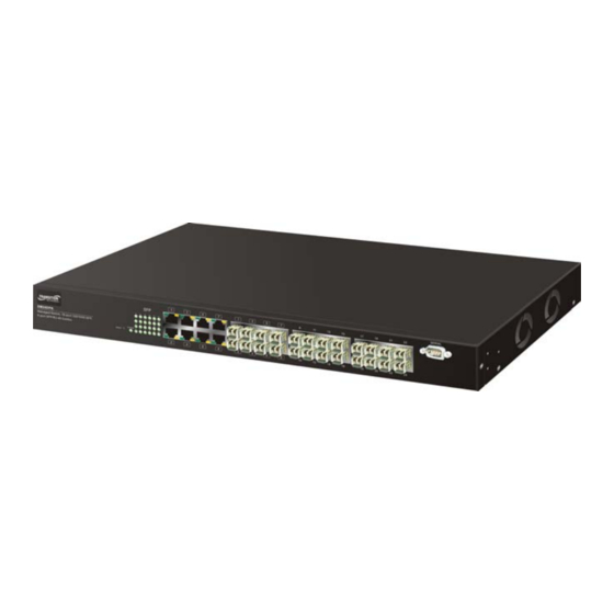
1-4. Full View of SM24DPA Fig. 1-1 Full View of SM24DPA 1-4-1. User Interfaces on the Front Panel (Button, LEDs and Plugs) There are 8 TP Gigabit Ethernet ports and 24 (100/1000) SFP fiber ports for optional removable modules on the front panel of the switch. LED display area, locating on the left side of the panel, contains a Power LED, which indicates the power status and 24 ports working status of the switch. -
Page 17: Ac Power Input On The Rear Panel
One socket on the rear panel is for AC power input. AC Line 100-240V 50/60 Hz Redundant Power Supply (RPS) Connector Fig. 1-3 Rear View of SM24DPA 1-5. View of the Optional SFP Modules Please visit our web page for the detail of the optional SFP modules: http://www.transition.com/TransitionNetworks/Landing/SFP-XFP/SFP-XFP.aspx Rev.A0... -
Page 18: Installation
Be sure that power switch is OFF before you insert the power cord to power source • Installing Optional SFP Fiber Transceivers to the SM24DPA Note: If you have no modules, please skip this section. Fig. 2-1 Installation of Optional SFP Fiber Transceiver •... - Page 19 Gigabit 10/100/1000 TP device. Now, you can start having the switch in operation. • AC Power On ( SM24DPA only) The switch supports 100-240 VAC, 50-60 Hz power supply. The power supply will automatically convert the local AC power source to DC power. It does not matter whether any connection plugged into the switch or not when power on, even modules as well.
-
Page 20: Installing Chassis To A 19-Inch Wiring Closet Rail
2-1-2. Installing Chassis to a 19-Inch Wiring Closet Rail Fig. 2-2 Caution: Allow a proper spacing and proper air ventilation for the cooling fan at both sides of the chassis. Wear a grounding device for electrostatic discharge. Screw the mounting accessory to the front side of the switch (See Fig. 2-2). ... - Page 21 OSI layer 2 protocols such as 802.1d, 802.1q, LACP and so on. The fiber, TP cables and devices’ bit-time delay (round trip) are as follows: 1000Base-X TP, Fiber 100Base-TX TP 100Base-FX Fiber Round trip Delay: 4096 Round trip Delay: 512 Cat.
- Page 22 Fig. 2-4 Port-based VLAN Diagram 1. The same VLAN members could not be in different switches. 2. Every VLAN members could not access VLAN members each other. 3. The switch manager has to assign different names for each VLAN groups at one switch.
- Page 23 Fig. 2-6 Attribute-based VLAN Diagram Rev.A0 1-Mar-11...
-
Page 24: Configuring The Management Agent Of Sm24Dpa
RS-232 console, CLI, and Web. Users can use any one of them to monitor and configure the switch. You can touch them through the following procedures. Section 2-1-4-1: Configuring the Management Agent of SM24DPA through the Serial RS-232 Port... - Page 25 255.255.255.0. You can change the switch’s default IP address 192.168.1.77 to 10.1.1.1 and set the subnet mask to be 255.255.255.0. Then, choose your default gateway, may be it is 10.1.1.254. Default Value SM24DPA Your Network Setting IP Address 192.168.1.77 10.1.1.1 Subnet 255.255.255.0...
-
Page 26: Configuring The Management Agent Of Sm24Dpa Through The Serial Rs-232 Port16 2-1-4-2. Configuring The Management Agent Of Sm24Dpa Through The Ethernet Port
2-1-4-2. Configuring the Management Agent of SM24DPA through the Ethernet Port There are three ways to configure and monitor the switch through the switch’s Ethernet port. They are CLI, Web browser and SNMP manager. The user interface for the last one is NMS dependent and does not cover here. We just introduce the first two types of management interface. - Page 27 Fig. 2-10 the Login Screen for Web Rev.A0 1-Mar-11...
-
Page 28: Ip Address Assignment
2-1-5. IP Address Assignment For IP address configuration, there are three parameters needed to be filled in. They are IP address, Subnet Mask, Default Gateway and DNS. IP address: The address of the network device in the network is used for internetworking communication. - Page 29 Bit # 01 2 15 16 Network address Host address Class C: IP address range between 192.0.0.0 and 223.255.255.255. Each class C network has a 24-bit network prefix followed 8-bit host address. There are 2,097,152 (2^21)/24 networks able to be defined with a maximum of 254 (2^8 –2) hosts per network.
- Page 30 Not all IP address is available in the sub-netted network. Two special addresses are reserved. They are the addresses with all zero’s and all one’s host number. For example, an IP address 128.1.2.128, what IP address reserved will be looked like? All 0s mean the network itself, and all 1s mean IP broadcast. 128.1.2.128/25 Network Subnet...
- Page 31 According to the scheme above, a subnet mask 255.255.255.0 will partition a network with the class C. It means there will have a maximum of 254 effective nodes existed in this sub-netted network and is considered a physical network in an autonomous network.
-
Page 32: Typical Applications
2-2. Typical Applications The SM24DPA implements 8 Gigabit Ethernet TP ports with auto MDIX and two slots for the removable module supporting comprehensive fiber types of connection, including LC and BiDi-LC SFP modules. For more details on the specification of the switch, please refer to Appendix A. - Page 33 Fig. 2-14 Peer-to-peer Network Connection Fig. 2-15 Office Network Connection Rev.A0 1-Mar-11...
-
Page 34: Operation Of Web-Based Management
3. Operation of Web-based Management This chapter instructs you how to configure and manage the SM24DPA through the web user interface it supports, to access and manage the 16-Port Gigabit SFP and 8-Port Gigabit TP/SFP Fiber management Ethernet switch. With... - Page 35 To optimize the display effect, we recommend you use Microsoft IE 6.0 above, Netscape V7.1 above or FireFox V1.00 above and have the resolution 1024x768. The switch supported neutral web browser interface. In Fig. 3-2, for example, left section is the whole function tree with web user interface and we will travel it through this chapter.
-
Page 36: Web Management Home Overview
3-1. Web Management Home Overview After you login, the switch shows you the system information as Fig. 3-2. This page is default and tells you the basic information of the system, including “Model Name”, “System Description”, “Location”, “Contact”, “Device Name”, “System Up Time”, “Current Time”, “BIOS Version”, “Firmware Version”, “Hardware-Mechanical Version”, “Serial Number”, “Host IP Address”, “Host Mac Address”, “Device Port”, “RAM Size”... - Page 37 • The Information of Page Layout On the top side, it shows the front panel of the switch. In the front panel, the linked ports will display green; as to the ports, which are link off, they will be dark.
- Page 38 Root System Port VLAN GVRP SNMP IP MAC Binding 802.1X TACACS+ Trunk MSTP Mirroring Multicast Alam DHCP Snooping LLDP Save/Restore Export/ Import Diagnostics Maintenance Logout Rev.A0 1-Mar-11...
-
Page 39: System Information
3-1-1. System Information Function name: System Information Function description: Show the basic system information. Fig. 3-4 Parameter description: Model name: The model name of this device. System description: 16-Port SFP + 8-Port As it is, this tells what this device is. Here, it is “ Combo Port GbE L2 Plus Managed Switch ”. - Page 40 You can configure this parameter through the device’s user interface or SNMP. Device name: SM24DPA The name of the switch. User-defined. Default is System up time: The time accumulated since this switch is powered up. Its format is day, hour, minute, second.
- Page 41 To display the Redundant Power Supply system model name. Hardware Mechanical Version: To display the Redundant Power Supply system hardware mechanical version. Serial Number : To display the Redundant Power Supply system serial number. Temperature : To display the Redundant Power Supply system temperature with ‘C and ‘F.
-
Page 42: Account Configuration
3-1-2. Account Configuration In this function, only administrator can create, modify or delete the username and password. Administrator can modify other guest identities’ password without confirming the password but it is necessary to modify the administrator-equivalent identity. Guest-equivalent identity can modify his password only. Please note that you must confirm administrator/guest identity in the field of Authorization in advance before configuring the username and password. -
Page 43: Time Configuration
3-1-3. Time Configuration The switch provides manual and automatic ways to set the system time via NTP. Manual setting is simple and you just input “Year”, “Month”, “Day”, “Hour”, “Minute” and “Second” within the valid value range indicated in each item. If you input an invalid value, for example, 61 in minute, the switch will clamp the figure to NTP is a well-known protocol used to synchronize the clock of the switch system time over a network. - Page 44 is no time zone setting in Manual mode. Default: Year = 2000, Month = 1, Day = 1 Hour = 0, Minute = 0, Second = 0 NTP: NTP is Network Time Protocol and is used to sync the network time based Greenwich Mean Time (GMT).
- Page 45 Default: 0 Day Light Saving End : This is used to set when to stop performing the daylight saving time. Mth: Range is 1 ~ 12. Default: 1 Day: Range is 1 ~ 31. Default: 1 Hour: Range is 0 ~ 23. Default: 0 Rev.A0 1-Mar-11...
-
Page 46: Ip Configuration
3-1-4. IP Configuration IP configuration is one of the most important configurations in the switch. Without the proper setting, network manager will not be able to manage or view the device. The switch supports both manual IP address setting and automatic IP address setting via DHCP server. - Page 47 IP address: Users can configure the IP settings and fill in new values if users set the DHCP function “Disable”. Then, click <Apply> button to update. When DHCP is disabled, Default: 192.168.1.77 If DHCP is enabled, this field is filled by DHCP server and will not allow user manually set it any more.
- Page 48 DNS: It is Domain Name Server used to serve the translation between IP address and name address. The switch supports DNS client function to re-route the mnemonic name address to DNS server to get its associated IP address for accessing Internet.
-
Page 49: Loop Detection
3-1-5. Loop Detection The loop detection is used to detect the presence of traffic. When switch receives packet’s(looping detection frame) MAC address the same as oneself from port, show Loop detection happens. The port will be locked when it received the looping detection frames. -
Page 50: Management Policy
3-1-6. Management Policy Through the management security configuration, the manager can do the strict setup to control the switch and limit the user to access this switch. The following rules are offered for the manager to manage the switch: Rule 1) : When no lists exists, then it will accept all connections. Accept ----------------------------------------------------------------------- Rule 2) : When only “accept lists”... - Page 51 Function name: Management Security Configuration Function description: The switch offers Management Security Configuration function. With this function, the manager can easily control the mode that the user connects to the switch. According to the mode, users can be classified into two types: Those who are able to connect to the switch (Accept) and those who are unable to connect to the switch (Deny).
- Page 52 Name: A name is composed of any letter (A-Z, a-z) and digit (0-9) with maximal 8 characters. VID: The switch supports two kinds of options for managed valid VLAN VID, including “Any” and “Custom”. Default is “Any”. When you choose “Custom”, you can fill in VID number.
-
Page 53: Syslog
3-1-7. Syslog The Syslog is a standard for logging program messages . It allows separation of the software that generates messages from the system that stores them and the software that reports and analyzes them. It can be used as well a generalized informational, analysis and debugging messages. -
Page 54: System Log
3-1-8. System Log The System Log provides information about system logs, including information when the device was booted, how the ports are operating, when users logged in, when sessions timed out, as well as other system information. Function name: System Log Function description: The Trap Log Data is displaying the log items including all SNMP Private Trap events, SNMP Public traps and user logs occurred in the system. -
Page 55: Virtual Stack
3-1-9. Virtual Stack Function name: Virtual Stack Function description: Virtual Stack Management(VSM) is the group management function. Through the proper configuration of this function, switches in the same LAN will be grouped automatically. And among these switch, one switch will be a master machine, and the others in this group will become the slave devices. - Page 56 Parameter description: State: It is used for the activation or de-activation of VSM. Default is Enable. Role: The role that the switch would like to play in virtual stack. Two types of roles, including master and slave are offered for option. Default is Master. Group ID: It is the group identifier (GID) which signs for VSM.
-
Page 57: Port Configuration
3-2. Port Configuration Four functions, including Port Status, Port Configuration, Simple Counter and Detail Counter are contained in this function folder for port monitor and management. Each of them will be described in detail orderly in the following sections. Port Configuration Configuration Status Simple Counter... - Page 58 Parameter description: Port: To display the port index Media: To display the port media type with UTP or SFP Speed: Set the speed and duplex of the port. In speed, if the media is 1Gbps fiber, it is always 1000Mbps and the duplex is full only. If the media is TP, the Speed/Duplex is comprised of the combination of speed mode, 10/100/1000Mbps, and duplex mode, full duplex and half duplex.
-
Page 59: 3-2-2.Port Status
3-2-2.Port Status The function Port Status gathers the information of all ports’ current status and reports it by the order of port number, media, link status, port state, Auto- Negotiation status, speed/duplex, Rx Pause and Tx Pause. An extra media type information for the module ports1 to 8 is also offered (See Fig. - Page 60 100Mbps and 1000Mbps supported for TP media, and the duplex supported is half duplex and full duplex. If the media is 1Gbps fiber, it is 1000Mbps supported only. The status of speed/duplex mode is determined by 1) the negotiation of both local port and link partner in “Auto Speed”...
- Page 61 Parameter description of Port 1 ~ Port 24: Connector Type: Display the connector type, for instance, UTP, SC, ST, LC and so Fiber Type: Display the fiber mode, for instance, Multi-Mode, Single-Mode. Tx Central Wavelength: Display the fiber optical transmitting central wavelength, for instance, 850nm, 1310nm, 1550nm and so on.
-
Page 62: Simple Counter
3-2-3. Simple Counter The function of Simple Counter collects any information and provides the counting about the traffic of the port, no matter the packet is good or bad. In the Fig. 3-15, the window can show all ports’ counter information at the same time. - Page 63 Errors: Transmit:: Number of bad packets transmitted. Receive: Number of bad packets received. Drops Transmit:: Number of packets transmitted drop. Receive: Number of packets received drop. Auto-refresh: The simple counts will be refreshed automatically on the UI screen. Refresh: The simple counts will be refreshed manually when user use mouse to click on “Refresh”...
-
Page 64: Detail Counter
3-2-4. Detail Counter The function of Detail Counter collects any information and provides the counting about the traffic of the port, no matter the packet is good or bad. In the Fig. 3-16, the window can show only one port counter information at the same time. - Page 65 Rx Broadcast: Show the counting number of the received broadcast packet. Rx Multicast: Show the counting number of the received multicast packet. Tx Packets: The counting number of the packet transmitted. TX Octets: Total transmitted bytes. Tx High Priority Packets: Number of Tx packets classified as high priority.
- Page 66 Number of 256 ~ 511-byte frames in good and bad packets transmitted. Tx 512-1023 Bytes: Number of 512 ~ 1023-byte frames in good and bad packets transmitted. Tx 1024-Bytes: Number of 1024-max_length-byte frames in good and bad packets transmitted. Rx CRC/Alignment: Number of Alignment errors and CRC error packets received.
-
Page 67: Power Saving
3-2-5. Power Saving The function of Power Saving and provides the Power saving for reduce the power consumption with "ActiPHY Power Management" and "PerfectReach Power Management" two technique.It could efficient saving the switch Power when the client idle and detec the cable length to provide different power. Function name: Power Saving Function description:... -
Page 68: Vlan
3-3. VLAN The switch supports Tag-based VLAN (802.1Q) and Port-based VLAN Support 4094 active VLANs and VLAN ID 1~4094. VLAN configuration is used to partition your LAN into small ones as your demand. Properly configuring it, you can gain not only improving security and increasing performance but greatly reducing VLAN management. - Page 69 Tag-based VLAN identifies its member by VID. This is quite different from port-based VLAN. If there are any more rules in ingress filtering list or egress filtering list, the packet will be screened with more filtering criteria to determine if it can be forwarded. The switch supports supplement of 802.1q.
- Page 70 segment port member without any change (for example: VLAN tag or un- tag frames). The L2 PDU will be passed through between two ports in the same LAN segment. (Including: STP, MSTP, GVRP, LACP,... ; Except 802.3X Pause Frame). Notice: The following L2 switch functions can not work with LAN segmentation mode at the same time: ...
-
Page 71: Tag-Based Group
3-3-2. Tag-based Group Function name: Tag-based Group Configuration Function description: It shows the information of existed Tag-based VLAN Groups, You can also easily create, edit and delete a Tag-based VLAN group by pressing <Add>, <Edit> and <Delete> function buttons. User can add a new VLAN group by inputting a new VLAN name and VLAN ID. - Page 72 Add new VLAN: Please click on <Add new VLAN> to create a new Tag-based VLAN. Input the VLAN name as well as VID, configure the SYM-VLAN function and choose the member by ticking the check box beside the port No., then, press the <Apply>...
- Page 73 Fig. 3-20-1 c. You need to assign these ports for member of port isolation. Fig. 3-20-2 d. Press the “Save” to complete the PVLAN configuration process. Rev.A0 1-Mar-11...
-
Page 74: Port-Based Group
3-3-3. Port-based Group Function name: Port-based Group Configuration Function description: It shows the information of the existed Port-based VLAN Groups. You can easily create, edit and delete a Port-based VLAN group by pressing <Add>, <Edit> and <Delete> function buttons. User can add a new VLAN group by inputting a new VLAN name. - Page 75 Delete Group: Just press the <Delete> button to remove the selected group entry from the Port-based group table. Fig. 3-23 Rev.A0 1-Mar-11...
-
Page 76: Ports
3-3-4. Ports Function name: VLAN Port Configuration Function description: In VLAN Tag Rule Setting, user can input VID number to each port. The range of VID number is from 1 to 4094. User also can choose ingress filtering rules to each port. There are two ingress filtering rules which can be applied to the switch. - Page 77 This PVID range will be 1-4094. Before you set a number x as PVID, you have to create a Tag-based VLAN with VID x. For example, if port x receives an untagged packet, the switch will apply the PVID (assume as VID y) of port x to tag this packet, the packet then will be forwarded as the tagged packet with VID y.
-
Page 78: Port Isolation
3-3-5. Port Isolation Function name: Port Isolation Function description: Port Isolation provides for an apparatus and method to isolate ports on layer 2 switches on the same VLAN to restrict traffic flow. The apparatus comprises a switch having said plurality of ports, each port configured as a protected port or a non-protected port. -
Page 79: Management Vlan
3-3-6. Management VLAN Function name: Management VLAN Function description: To assign a specific VLAN for management purpose. Fig. 3-25 Parameter description: VID: Specific Management VLAN ID. Rev.A0 1-Mar-11... -
Page 80: Mac
3-4. MAC MAC Table Configuration gathers many functions, including MAC Table Information, MAC Table Maintenance, Static Forward, Static Filter and MAC Alias, which cannot be categorized to some function type. They are described below. 3-4-1. Mac Address Table Function name: MAC Address Table Information Function Description: This function can allow the user to set up the processing mechanism of MAC... - Page 81 Disable automatic aging: Stop the MAC table aging timer, the learned MAC address will not age out automatically Auto: Enable this port MAC address dynamic learning mechanism. Disable: Disable this port MAC address dynamic learning mechanism, only support static MAC address setting. Secure: Disable this port MAC address dynamic learning mechanism and copy the dynamic learning packets to CPU...
-
Page 82: Static Filter
3-4-2. Static Filter Function name: Static Filter Function Description: Static Filter is a function that denies the packet forwarding if the packet’s MAC Address is listed in the filtering Static Filter table. User can very easily maintain the table by filling in MAC Address, VID (VLAN ID) and Alias fields individually. -
Page 83: Static Forward
3-4-3. Static Forward Function Name: Static Forward Function Description: Static Forward is a function that allows the user in the static forward table to access a specified port of the switch. Static Forward table associated with a specified port of a switch is set up by manually inputting MAC address and its alias name. -
Page 84: Mac Alias
3-4-4. MAC Alias Function name: MAC Alias Function description: MAC Alias function is used to let you assign MAC address a plain English name. This will help you tell which MAC address belongs to which user in the illegal access report. At the initial time, it shows all pairs of the existed alias name and MAC address. -
Page 85: Mac Table
3-4-5. MAC Table Function name: MAC Table Function Description: Display the static or dynamic learning MAC entry and the state for the selected port. Fig. 3-30 Parameter description: Alias: MAC alias name you assign. MAC address: Display the MAC address of one entry you selected from the searched MAC entries table. -
Page 86: Gvrp
3-5. GVRP GVRP is an application based on Generic Attribute Registration Protocol (GARP), mainly used to automatically and dynamically maintain the group membership information of the VLANs. The GVRP offers the function providing the VLAN registration service through a GARP application. It makes use of GARP Information Declaration (GID) to maintain the ports associated with their attribute database and GARP Information Propagation (GIP) to communicate among switches and end stations. - Page 87 Join Time: Used to declare the Join Time in unit of centisecond. Valid time range: 20 –100 centisecond, Default: 20 centisecond. Leave Time: Used to declare the Leave Time in unit of centisecond. Valid time range: 60 –300 centisecond, Default: 60 centisecond. Leave All Time: A time period for announcement that all registered device is going to be de-registered.
- Page 88 Disabled: In this mode, the switch dynamic VLAN will be created when this port received GVRP PDU. The default setting is Normal. Enabled: In this mode, the switch does not create dynamic VLAN when this port received GVRP PDU. Except received dynamic VLAN message of the GVRP PDU is an existed static VLAN in the switch, this port will be added into the static VLAN members dynamically.
-
Page 89: Counter
3-5-2. Counter Function name: GVRP Counter Function description: All GVRP counters are mainly divided into Received and Transmitted two categories to let you monitor the GVRP actions. Actually, they are GARP packets. Fig. 3-32 Parameter description: Received: Total GVRP Packets: Total GVRP BPDU is received by the GVRP application. - Page 90 Empty Message Packets: Number of GARP BPDU with Empty message is received by the GARP application. Transmitted: Total GVRP Packets: Total GARP BPDU is transmitted by the GVRP application. Invalid GVRP Packets: Number of invalid GARP BPDU is transmitted by the GVRP application.
-
Page 91: Group
3-5-3. Group Function name: GVRP Group VLAN Information Function description: To show the dynamic group member and their information. Fig. 3-33 Parameter description: VID: VLAN identifier. When GVRP group creates, each dynamic VLAN group owns its VID. Valid range is 1 ~ 4094. Member Port: Those are the members belonging to the same dynamic VLAN group. -
Page 92: Qos(Quality Of Service) Configuration
3-6. QoS(Quality of Service) Configuration support four QoS queues per port with strict or weighted fair switch queuing scheduling. There are 24 QoS Control Lists (QCL) for advance programmable QoS classification, based on IEEE 802.1p, Ethertype, VID, IPv4/IPv6 DSCP and UDP/TCP ports and ranges. High flexibility in the classification of incoming frames to a QoS class. - Page 93 Parameter description: Number of Classes: 1 / 2 / 4 Port: User can choose the port (1~24) respectively with Priority Class on Per Port Priority function. Default Class: User can set up High Priority or Low Priority for each port respectively. Low / Normal / Medium / High QCL: The number of QCL rule 1~24, each port have to apply one of the QCL...
-
Page 94: Qos Control List
3-6-2. Qos Control List Function name: Qos Control List Configuration Function description: support four QoS queues per port with strict or weighted fair switch queuing scheduling. There are 24 QoS Control Lists (QCL) for advance programmable QoS classification, based on IEEE 802.1p, Ether Type, VID, IPv4/IPv6 DSCP and UDP/TCP ports and ranges. - Page 95 Fig. 3-36 Fig. 3-37 Fig. 3-38 Rev.A0 1-Mar-11...
- Page 96 Fig. 3-39 Fig. 3-40 Fig. 3-41 Fig. 3-42 Rev.A0 1-Mar-11...
- Page 97 Parameter description: QCL#: QCL number : 1~24 QCE Type: Ethernet Type / VLAN ID / UDP/TCP Port / DSCP / ToS / Tag Priority Ethernet Type Value: The configurable range is 0x600~0xFFFF. Well known protocols already assigned EtherType values. The commonly used values in the EtherType field and corresponding protocols are listed below: Ethertype Protocol...
- Page 98 Protocol. MPLS, Multi-Protocol Label Switching 0x8847 (unicast). MPLS, Multi-Protocol Label Switching 0x8848 (multicast). PPPoE, PPP Over Ethernet (Discovery 0x8863 Stage). PPPoE, PPP Over Ethernet (PPP Session 0x8864 Stage). 0x88BB LWAPP, Light Weight Access Point Protocol. 0x88CC LLDP, Link Layer Discovery Protocol. 0x8E88 EAPOL, EAP over LAN.
-
Page 99: Rate Limiters
3-6-3. Rate Limiters Function name: Rate Limit Configuration Function description: Each port includes an ingress policer, and an egress shaper, which can limit the bandwidth of received and transmitted frames. Ingress policer or egress shaper operation is controlled per port in the Rate Limit Configuration. Fig. -
Page 100: Storm Control
3-6-4. Storm Control Function name: Storm Control Configuration Function description: The switch support storm ingress policer control function to limit the Flooded, Multicast and Broadcast to prevent storm event happen. Fig. 3-44 Parameter description: Frame Type: There three frame types of storm can be controlled: Flooded unicast / Multicast / Broadcast Status: Enable/Disable Selection:... -
Page 101: Wizard
3-6-5. Wizard Function name: Wizard Function description: The QCL configuration Wizard is targeted on user can easy to configure the QCL rules for QoS configuration. The wizard provide the typical network application rules, user can apply these application easily. Fig. 3-45 Parameter description: Please select an Action: User need to select one of action from following items, then click on... - Page 102 Fig. 3-46 Set up Port Policies Parameter description: QCL ID: QoS Control List (QCL): 1~24 Port Member: Port Member: 1~24 Fig. 3-47 Set up Port Policies Parameter description: Wizard Again: Click on the <Wizard Again> , back to QCL Configuration Wizard. Finish: When you click on <Finish>, the parameters will be set according to the wizard configuration and shown on the screen, then ask you to click on...
- Page 103 Fig. 3-48 Set up Port Policies Finish Fig. 3-49 Set up Typical Network Application Rules Fig. 3-50 Set up Typical Network Application Rules Rev.A0 1-Mar-11...
- Page 104 Fig. 3-51 Set up Typical Network Application Rules Parameter description: Audio and Video: QuickTime 4 Server / MSN Messenger Phone / Yahoo Messenger Phone / Napster / Real Audio Games: Blizzard Battlenet (Diablo2 and StarCraft) / Fighter Ace II / Quake2 / Quake3 / MSN Game Zone User Definition: Ethernet Type / VLAN ID / UDP/TCP Port / DSCP...
- Page 105 Fig. 3-52 Set up Typical Network Application Rules Parameter description: QCL ID: QCL ID Range: 1~24 Traffic Class: There are four classes: Low / Normal / Medium / High Fig. 3-53 Set up Typical Network Application Rules Rev.A0 1-Mar-11...
- Page 106 Fig. 3-54 Set up Typical Network Application Rules Finish Fig. 3-55 Set up Typical Network Application Rules Finish Rev.A0 1-Mar-11...
- Page 107 Fig. 3-56 Set up Typical Network Application Rules Finish Parameter description: QCL #: QoS Control List (QCL): 1~24 Fig. 3-57 Set up TOS Precedence Mapping Parameter description: QCL ID: QoS Control List (QCL): 1~24 TOS Precedence 0~7 Class: Low / Normal / Medium / High Rev.A0 1-Mar-11...
- Page 108 Fig. 3-58 Set up TOS Precedence Mapping Fig. 3-59 Set up TOS Precedence Mapping Finish Fig. 3-60 Set up VLAN Tag Priority Mapping Parameter description: QCL ID: QoS Control List (QCL): 1~24 Tag Priority 0~7 Class: Low / Normal / Medium / High Rev.A0 1-Mar-11...
- Page 109 Fig. 3-61 Set up VLAN Tag Priority Mapping Rev.A0 1-Mar-11...
- Page 110 Fig. 3-62 Set up VLAN Tag Priority Mapping Finish Rev.A0 1-Mar-11...
- Page 111 3-7. SNMP Configuration Any Network Management System (NMS) running the Simple Network Management Protocol (SNMP) can manage the Managed devices equipped with SNMP agent, provided that the Management Information Base (MIB) is installed correctly on the managed devices. The SNMP is a protocol that is used to govern the transfer of information between SNMP manager and agent and traverses the Object Identity (OID) of the management Information Base (MIB), described in the form of SMI syntax.
- Page 112 Function name: SNMPv3 Communities Configuration Function description: The function is used to configure SNMPv3 communities. The Community and UserName is unique. To create a new community account, please check <Add new community> button, and enter the account information then check <Save>. Max Group Number : 4.
- Page 113 Function name: SNMPv3 Users Configuration Function description: The function is used to configure SNMPv3 user. The Entry index key is UserName. To create a new UserName account, please check <Add new user> button, and enter the user information then check <Save>. Max Group Number : 10. Fig.
- Page 114 Function name: SNMPv3 Groups Configuration Function description: The function is used to configure SNMPv3 group. The Entry index key are Security Model and Security Name. To create a new group account, please check <Add new group> button, and enter the group information then check <Save>. Max Group Number : v1: 2, v2: 2, v3:10.
- Page 115 Function name: SNMPv3 Views Configuration Function description: The function is used to configure SNMPv3 view. The Entry index key are OID Subtree and View Name. To create a new view account, please check <Add new view> button, and enter the view information then check <Save>. Max Group Number : 28.
- Page 116 Function name: SNMPv3 Accesses Configuration Function description: The function is used to configure SNMPv3 accesses. The Entry index key are Group Name, Security Model and Security level. To create a new access account, please check <Add new access> button, and enter the access information then check <Save>.
- Page 117 Function name: Trap Hosts Configuration Function description: The function is used to configure SNMP trap. To create a new trap account, please check <No number> button, and enter the trap information then check <Apply>. Max Group Number : 6. Fig. 3-63-8 The Trap Hosts setting Fig.
- Page 118 SNMP Host IP address. Port: Port number. Default: 162 Community / Security Name: The length of “Community / Security Name” string is restricted to 1-32. Security Level: There are three kinds of choices. NoAuth, NoPriv: No authentication and no privacy. Auth, NoPriv: Authentication and no privacy.
-
Page 119: Acl
3-8. ACL The SM24DPA switch access control list (ACL) is probably the most commonly used object in the IOS. It is used for packet filtering but also for selecting types of traffic to be analyzed, forwarded, or influenced in some way. - Page 120 Policy ID: Policy ID range:1~8 Action: Permit or Deny forwarding the met ACL packets Rate Limiter ID: Disabled: Disable Rate Limitation Rate Limiter ID Range: 1~16. To select one of rate limiter ID for this port, it will limit met ACL packets by rate limiter ID configuration. Port Copy: Disabled: Disable to copy the met ACL packets to specific port Port number: 1~24.
-
Page 121: Rate Limiters
3-8-2. Rate Limiters Function name: ACL Rate Limiter Configuration Function description: There are 16 rate limiter ID. You can assign one of the limiter ID for each port. The rate limit configuration unit is Packet Per Second (pps). Fig. 3-65 Parameter description: Rate Limiter ID: ID Range: 1~16... -
Page 122: Access Control List
3-8-3. Access Control List Function name: ACL Rate Limiter Configuration Function description: The switch ACL function support up to 128 Access Control Entries (ACEs), using the shared 128 ACEs for ingress classification. You can create an ACE and assign this ACE for each port with <Any> or assign this ACE for a policy or assign this ACE for a port. - Page 123 Ingress Port Fig. 3-67 Fig. 3-68 Parameter description: Frame Type: Range: Any / Ethernet Type / ARP / IPv4 Any: It is including all frame type Ethernet Type: It is including all Ethernet frame type ARP: It is including all ARP protocol frame type IPv4: It is including all IPv4 protocol frame type Rev.A0 1-Mar-11...
- Page 124 Fig. 3-69 Frame Type Fig. 3-70 Rev.A0 1-Mar-11...
- Page 125 Fig. 3-71 Fig. 3-72 Fig. 3-73 ARP Rev.A0 1-Mar-11...
- Page 126 Fig. 3-74 ARP Fig. 3-75 ARP Fig. 3-76 ARP Fig. 3-77 ARP Rev.A0 1-Mar-11...
- Page 127 Fig. 3-79 ARP Fig. 3-80 ARP Fig. 3-81 ARP Rev.A0 1-Mar-11...
- Page 128 Fig. 3-82 ARP Fig. 3-83 ARP Fig. 3-84 ARP Fig. 3-85 ARP Fig. 3-86 ARP Rev.A0 1-Mar-11...
- Page 129 Fig. 3-87 ARP Fig. 3-88 IPv4 Rev.A0 1-Mar-11...
- Page 130 Fig. 3-89 IPv4 Fig. 3-90 IPv4 Fig. 3-91 IPv4 Fig. 3-92 IPv4 Fig. 3-93 IPv4 Rev.A0 1-Mar-11...
- Page 131 Fig. 3-94 IPv4 Fig. 3-95 IPv4 Fig. 3-96 IPv4 Fig. 3-97 IPv4 Fig. 3-98 IPv4 Rev.A0 1-Mar-11...
- Page 132 Fig. 3-99 IPv4 Fig. 3-100 IPv4 Fig. 3-101 IPv4 Fig. 3-102 IPv4 Rev.A0 1-Mar-11...
- Page 133 Fig. 3-103 IPv4 Fig. 3-104 IPv4 Fig. 3-105 IPv4 Rev.A0 1-Mar-11...
- Page 134 Fig. 3-106 IPv4 Fig. 3-107 IPv4 Fig. 3-108 IPv4 Rev.A0 1-Mar-11...
- Page 135 Fig. 3-109 IPv4 Fig. 3-110 IPv4 Fig. 3-111 IPv4 Rev.A0 1-Mar-11...
- Page 136 Fig. 3-112 IPv4 Fig. 3-113 IPv4 Fig. 3-114 IPv4 Rev.A0 1-Mar-11...
- Page 137 Fig. 3-115 IPv4 Fig. 3-116 IPv4 Fig. 3-117 IPv4 Rev.A0 1-Mar-11...
- Page 138 Fig. 3-118 Action Fig. 3-119 Rate Limiter Rev.A0 1-Mar-11...
- Page 139 Fig. 3-120 Port Copy Fig. 3-121 DMAC Filter Rev.A0 1-Mar-11...
- Page 140 Fig. 3-122 VLAN ID Filter Fig. 3-123 VLAN ID Filter Fig. 3-124 Tag Priority Rev.A0 1-Mar-11...
- Page 141 Function name: ACE Configuration Function description: The switch ACL function support up to 128 Access Control Entries (ACEs), using the shared 128 ACEs for ingress classification. You can create an ACE and assign this ACE for each port with <Any> or assign this ACE for a policy or assign this ACE for a port.
- Page 142 MAC Parameters: (When Frame Type = ARP) SMAC Filter: Range: Any / Specific Any: It is including all source MAC address Specific: It is according to SMAC Value specific the source MAC address DMAC Filter: Range: Any / MC / BC / UC Any: It is including all destination MAC address MC: It is including all Multicast MAC address BC: It is including all Broadcast MAC address...
- Page 143 Sender IP Filter: Range: Any / Host / Network Any: Including all sender IP address Host: Only one specific sender host IP address Network: A specific IP subnet segment under the sender IP mask Sender IP Address: Default: 192.168.1.77 Sender IP Mask: Default: 255.255.255.0 Target IP Filter: Range: Any / Host / Network...
- Page 144 Both 0 and 1 The ingress ARP/PARP frames where the Hardware size is not equal "0x6" or the Protocol size is not equal "0x4" The ingress ARP/PARP frames where the Hardware size is equal "0x6" and the Protocol size is "0x4" Range: Any / 0 / 1 Any: Both 0 and 1...
- Page 145 No: The ingress frames is not fragmented packet IP Option: A list of optional specifications for security restrictions, route recording, and source routing. Not every datagram specifies an options field. Range: Any / Yes / No Any: Including all IP option case Yes: The ingress frame is specified IP options No: The ingress frame is not specified IP options SIP Filter: (SIP Source IP Address)
- Page 146 Specific: According to following ICMP code value setting for ingress classification ICMP Code Value: Range: 0-255 IP Parameters: (Frame Type = IPv4 and IP Protocol Filter = UDP) Source Port Filter: Range: Any / Specific / Range Any: Including all UDP source ports Specific: According to following Source Port No.
- Page 147 Range: 0-65535 Source Port Range.: Range: 0-65535 Dest. Port Filter: Range: Any / Specific / Range Any: Including all TCP destination ports Specific: According to following Dest. Port No. setting for ingress classification Range: According to following Dest. Port Range setting for ingress classification Dest.
- Page 148 0: The TCP control bit PSH is 0 1: The TCP control bit PSH is 1 TCP ACK: TCP Control Bit ACK: Means Acknowledgment field significant Range: Any / 0 / 1 Any: Including all TCP ACK case 0: The TCP control bit ACK is 0 1: The TCP control bit ACK is 1 TCP URG: TCP Control Bit URG: Means Urgent Pointer field significant...
- Page 149 Controls datagram fragmentation together with the identification field. The flags indicate whether the datagram may be fragmented, whether the datagram is fragmented, and whether the current fragment is the final one. Range: Any / Yes / No Any: Including all IP fragment case Yes: The ingress frame is fragmented packet No: The ingress frames is not fragmented packet IP Option:...
- Page 150 ingress classification VLAN ID: Range: 1-4094 Tag Priority: Range: Any / 0-7 Any: Including all Tag Priority values 0-7: The Tag Priority Value is one of number (0-7) Action Parameters: When the ingress frame meet above ACL ingress classification rule you can do the following actions: Action: Range: Permit / Deny...
-
Page 151: 3-8-4.Wizard
3-8-4.Wizard Function name: Wizard Function description: The wizard function is provide 4 type of typical application for user easy to configure their application with ACL function. Fig. 3-125 Wizard Parameter description: Please select an Action: Set up Policy Rules / Set up Port Policies / Set up Typical Network Application Rules / Set up Source MAC and Source IP Binding Next: Click on <Next>... - Page 152 Fig. 3-126 Set up Policy Rules Fig. 3-127 Set up Policy Rules Fig. 3-128 Set up Policy Rules Rev.A0 1-Mar-11...
- Page 153 Fig. 3-129 Set up Policy Rules Finish Fig. 3-130 Set up Port Policies Fig. 3-131 Set up Port Policies Rev.A0 1-Mar-11...
- Page 154 Fig. 3-132 Set up Port Policies Fig. 3-133 Set up Port Policies Finish Fig. 3-134 Set up Typical Network Application Rules Rev.A0 1-Mar-11...
- Page 155 Fig. 3-135 Set up Typical Network Application Rules Fig. 3-136 Set up Typical Network Application Rules Fig. 3-137 Set up Typical Network Application Rules Rev.A0 1-Mar-11...
- Page 156 Fig. 3-138 Set up Typical Network Application Rules Finish Parameter description: Common Server: DHCP / DNS / FTP / HTTP / IMAP / NFS / POP3 / SAMBA / SMTP / TELNET / TFTP Instant Messaging: Google Talk / MSN Messenger / Yahoo Messenger User Definition: Ethernet Type / UDP Port / TCP Port Others:...
-
Page 157: Ip Mac Binding
3-9. IP MAC Binding The IP network layer uses a four-byte address. The Ethernet link layer uses a six-byte MAC address. Binding these two address types together allows the transmission of data between the layers. The primary purpose of IP-MAC binding is to restrict the access to a switch to a number of authorized users. - Page 158 Server/Client: The maximum number of IP-MAC binding client table is 512 entries. The maximum number of IP-MAC Binding server table is 64 entries. MAC: Six-byte MAC Address: xx-xx-xx-xx-xx-xx For example: 00-40-c7-00-00-01 Four-byte IP Address: xxx.xxx.xxx.xxx For example: 192.168.1.100 Port No: Port no.: 1-24 VID: VLAN ID: 1-4094...
-
Page 159: Configuration
3-10. 802.1X Configuration 802.1X port-based network access control provides a method to restrict users to access network resources via authenticating user’s information. This restricts users from gaining access to the network resources through a 802.1X- enabled port without authentication. If a user wishes to touch the network through a port under 802.1X control, he (she) must firstly input his (her) account name for authentication and waits for gaining authorization before sending or receiving any packets from a 802.1X-enabled port. - Page 160 The overview of operation flow for the Fig. 3-53 is quite simple. When Supplicant PAE issues a request to Authenticator PAE, Authenticator and Supplicant exchanges authentication message. Then, Authenticator passes the request to RADIUS server to verify. Finally, RADIUS server replies if the request is granted or denied.
- Page 161 Fig. 3-54 Rev.A0 1-Mar-11...
- Page 162 The Fig. 3-55 shows the procedure of 802.1X authentication. There are steps for the login based on 802.1X port access control management. The protocol used in the right side is EAPOL and the left side is EAP. At the initial stage, the supplicant A is unauthenticated and a port on switch acting as an authenticator is in unauthorized state.
- Page 163 supplicant and the devices connected to this port won’t be allowed to access the network. When supplicant issue EAP-Logoff message Authentication server, the port you are using is set to be unauthorized. Fig. 3-55 Only MultiHost 802.1X is the type of authentication supported in the switch. In this mode, for the devices connected to this port, once a supplicant is authorized, the devices connected to this port can access the network resource through this port.
-
Page 164: 3-10-1.Server
3-10-1.Server Function name: 802.1X Server Configuration Function description: This function is used to configure the global parameters for RADIUS authentication in 802.1X port security application. Fig. 3-144 Parameter description: Authentication Server Server IP Server: Server IP address for authentication. Default: 192.168.1.77 UDP Port: Default port number is 1812. - Page 165 Default: 192.168.1.77 UDP Port: Default port number is 1812. Secret Key: The secret key between authentication server and authenticator. It is a string with the length 1 – 31 characters. The character string may contain upper case, lower case and 0-9. It is character sense. It is not allowed for putting a blank between any two characters.
-
Page 166: 3-10-2.Port Configuration
3-10-2.Port Configuration Function name: 802.1X Port Configuration Function description: This function is used to configure the parameters for each port in 802.1X port security application. Refer to the following parameters description for details. Fig. 3-145 Parameter description: Port: It is the port number to be selected for configuring its associated 802.1X parameters which are Port control, reAuthMax, txPeriod, Quiet Period, reAuthEnabled, reAuthPeriod, max. - Page 167 Advanced: Each clients under this port have to do 802.1X authentication by himself. Clientless: The clients don’t need to install 802.1X client function, that means the client PC (for example WINDOW XP) does not need to enable 802.1X client function also can do 802.1X authentication. But the network maintainer need to configure the Radius server using each client’s MAC address for Radius account ID and password.
- Page 168 max. Request(1-10): The maximum of number times that the authenticator will retransmit an EAP Request to the supplicant before it times out the authentication session. The valid range: 1 – 10. Default: 2 times suppTimeout(1-65535 s): A timeout condition in the exchange between the authenticator and the supplicant.
-
Page 169: 3-10-3.Status
3-10-3.Status Function name: 802.1X Status Function description: Show the each port IEEE 802.1X authentication current operating mode and status. Fig. 3-146 Parameter description: Port: Port number: 1-24 Mode: Show this port IEEE 802.1X operating mode: There are four modes Disable, Normal, Advance and Clientless Status: Show this port IEEE 802.1X security current status: Authorized or Unauthorized Vlan Policy:... -
Page 170: Statistics
3-10-4. Statistics Function name: 802.1X Port Statistics Port1 Function description: Show the IEEE 802.1X authentication related counters for manager monitoring authenticator status. Fig. 3-147 Parameter description: Port: Port Number: 1-24 Auto - refresh: Refresh the authenticator counters in the web UI automatically Refresh: Click on the <Refresh>... -
Page 171: Tacacs
3-11. TACACS+ TACACS+ (Terminal Access Controller Access-Control System Plus) is a protocol which provides access control for the switch via one or more centralized servers. It provides separate authentication, authorization and accounting services. TACACS+ utilizes TCP port 49. It consists of three separate protocols, which can, if desired, be implemented on separate servers. -
Page 172: Authentication
3-11-2. Authentication Function name: Authentication Configuration Function description: The switch supports including Console, Telnet and Web authentication method via TACACS+ server . Fig. 3-147-1 Parameter description: Console: To set console authentication method with Login primary or Login secondary. Default: Primary is “Local” and Secondary is “None” Telnet: To set Telnet authentication method with Login primary or Login secondary. -
Page 173: Authorization
3-11-3. Authorization Function name: Authorization Configuration Function description: The switch supports TACACS+ server Authorization method with “State” and “Fallback to Local Authorization “. Fig. 3-147-1 Parameter description: State: To enable or disable the State Authorization via TACACS+ Server. Default: Disable Fallback to Local Authorization: To enable or disable the switch Fallback to Local Authorization. -
Page 174: Accounting
3-11-4. Accounting Function name: Accounting Configuration Function description: The switch supports TACACS+ server Accounting method with “Enable” and “Disable “ for manage login traffic accounting. Fig. 3-147-1 Parameter description: State: To enable or disable the accounting via TACACS+ Server. Default: Disable Rev.A0 1-Mar-11... -
Page 175: Trunking Configuration
3-12. Trunking Configuration The Port Trunking Configuration is used to configure the settings of Link Aggregation. You can bundle more than one port with the same speed, full duplex and the same MAC to be a single logical port, thus the logical port aggregates the bandwidth of these ports. -
Page 176: 3-12-1.Port
Per Trunking Group supports a maximum of 12 ready member-ports. Please note that some decisions will automatically be made by the system while you are configuring your trunking ports. Some configuration examples are listed below: 12 ports have already used Static Trunk Group ID 1, the 13th port willing to use the same Static Trunk Group ID will be automatically set to use the “None”... - Page 177 Method: This determines the method a port uses to aggregate with other ports. None: A port does not want to aggregate with any other port should choose this default setting. LACP: A port use LACP as its trunk method to get aggregated with other ports also using LACP.
-
Page 178: Aggregator View
3-12-2 Aggregator View Function name: Aggregator View Function description: To display the current port trunking information from the aggregator point of view. Fig.3-149 Parameter description: Aggregator: It shows the aggregator ID (from 1 to 24) of every port. In fact, every port is also an aggregator, and its own aggregator ID is the same as its own Port No.. -
Page 179: Aggregation Hash Mode
3-12-3 Aggregation Hash Mode Function name: Aggregation Hash Mode Configuration Function description: To configure the current port aggregate mode with 4 types. Fig.3-149-1 Parameter description: Source MAC Address: To evoke to enable source MAC address for Aggregate Mode . Destination MAC Address: To evoke to enable destination MAC address for Aggregate Mode . -
Page 180: Lacp System Priority
3-12-4 LACP System Priority Function name: LACP System Priority Function description: It is used to set the priority part of the LACP system ID. LACP will only aggregate together the ports whose peer link partners are all on a single system. -
Page 181: Stp Configuration
3-13 STP Configuration The Spanning Tree Protocol (STP) is a standardized method (IEEE 802.1D) for avoiding loops in switched networks. When STP is enabled, ensure that only one path is active between any two nodes on the network at a time. User can enable Spanning Tree Protocol on switch’s web management and then set up other advanced items. - Page 182 Designated Priority: Show the current root bridge priority. Root Port: Show port number connected to root bridge with the lowest path cost. Root Path Cost: Show the path cost between the root port and the designated port of the root bridge. Current Max.
-
Page 183: Configuration
If you want to have the SM24DPA as root bridge, you can set this value lower than that of bridge in the LAN. The valid value is 0 ~ 61440. The default is 32768. - Page 184 Default is 2 seconds. Max. Age: When the SM24DPA is the root bridge, the whole LAN will apply this figure set by this switch as their maximum age time. When a bridge received a BPDU originated from the root bridge and if the message age conveyed in the BPDU exceeds the Max.
-
Page 185: Stp Port Configuration
3-13-3. STP Port Configuration Function name: STP Port Setting Function description: In the STP Port Setting, one item selection and five parameters settings are offered for user’s setup. User can disable and enable each port by selecting each Port Status item. User also can set “Path Cost” and “Priority” of each port by filling in the desired value and set “Admin Edge Port”... - Page 186 Configured Path Cost: The range is 0 – 200,000,000. In the switch, if path cost is set to be zero, the STP will get the recommended value resulted from auto-negotiation of the link accordingly and display this value in the field of Path Cost Status.
- Page 187 Default: Auto M Check: Migration Check. It forces the port sending out an RSTP BPDU instead of a legacy STP BPDU at the next transmission. The only benefit of this operation is to make the port quickly get back to act as an RSTP port. Click <M Check>...
-
Page 188: Mstp
3-14 MSTP The implementation of MSTP is according to IEEE 802.1Q 2005 Clause 13 – Multiple Spanning Tree Protocol. MSTP allows frames assigned to different VLANs to follow separate paths, each based on an independent Multiple Spanning Tree Instance (MSTI), within Multiple Spanning Tree (MST) Regions composed of LANs and or MST Bridges. -
Page 189: Region Config
3-14-2. Region Config Function name: MSTP Region Config Function description: To configure the basic identification of a MSTP bridge. Bridges participating in a common MST region must have the same Region Name and Revision Level. Fig. 3-155 Parameter description: Region Name: 0-32 characters.(A variable length text string encoded within a fixed field of 32 octets , conforming to RFC 2271’s definition of SnmpAdminString.) Revision Level:... -
Page 190: Instance View
3-14-3. Instance View Function name: MSTP Instance Config Function description: Providing an MST instance table which include information(vlan membership of a MSTI ) of all spanning instances provisioned in the particular MST region which the bridge belongs to. Through this table, additional MSTP configuration data can be applied and MSTP status can be retrieved. - Page 191 Del MSTI: To delete an MSTI. Del All MSTI: Deleting all provisioned MSTIs at a time. Instance Configuration: Fig. 3-158 To provision spanning tree performance parameters per instance. Port Config: Fig. 3-159 To provision spanning tree performance parameters per instance per port. Instance Status: Fig.
- Page 192 Fig. 3-158 Instance Config Parameter description: Priority: The priority parameter used in the CIST(Common and Internal Spanning Tree) connection. 0 / 4096 / 8192 / 12288 / 16384 / 20480 / 24576 / 28672 / 32768 / 36864 / 40960 / 45056 / 49152 / 53248 / 57344 / 61440 MAX.
- Page 193 Fig. 3-159 Port Config Parameter description: Port: 1-24 Path Cost: 1 – 200,000,000 The same definition as in the RSTP specification. But in MSTP, this parameter can be respectively applied to ports of CIST and ports of any MSTI. Priority: 0 / 16 / 32 / 48 / 64 / 80 / 96 / 112 / 128 / 144 / 160 / 176 / 192 / 208 / 224 / 240 The same definition as in the RSTP specification.
- Page 194 Restricted Role: Yes / No If “Yes” causes the Port not to be selected as Root Port for the CIST or any MSTI, even it has the best spanning tree priority vector. Such a Port will be selected as an Alternate Port after the Root Port has been selected.
- Page 195 Parameter description: MSTP State: MSTP protocol is Enable or Disable. Force Version: It shows the current spanning tree protocol version configured. Bridge Max Age: It shows the Max Age setting of the bridge itself. Bridge Forward Delay: It shows the Forward Delay setting of the bridge itself. Bridge Max Hops: It shows the Max Hops setting of the bridge itself.
- Page 196 CIST INTERNAL ROOT PATH COST: Root path cost value from the point of view of the bridges inside the IST. CIST CURRENT MAX AGE: Max Age of the CIST Root bridge. CIST CURRENT FORWARD DELAY: Forward Delay of the CIST Root bridge. TIME SINCE LAST TOPOLOGY CHANGE(SECs): Time Since Last Topology Change is the elapsed time in unit of seconds for a bunch of “Topology Change and(or) Topology Change Notification...
- Page 197 Priority: Display port priority value for each port in a particular spanning tree instance. Hello: per port Hello Time display. It takes the following form: Current Hello Time/Hello Time Setting Oper. Edge: Whether or not a port is an Edge Port in reality. Oper.
-
Page 198: Mirror
3-15. Mirror Function name: Mirror Configuration Function description: Mirror Configuration is to monitor the traffic of the network. For example, we assume that Port A and Port B are Monitoring Port and Monitored Port respectively, thus, the traffic received by Port B will be copied to Port A for monitoring. -
Page 199: Multicast
Multicast 3-16. The function, is used to establish the multicast groups to forward the multicast packet to the member ports, and, in nature, avoids wasting the bandwidth while IP multicast packets are running over the network. This is because a switch that does not support IGMP or IGMP Snooping can not tell the multicast packet from the broadcast packet, so it can only treat them all as the broadcast packet. -
Page 200: Igmp Proxy
3-16-2. IGMP Proxy Function name: IGMP Proxy Configuration Function description: IGMP proxy enables the switch to issue IGMP host messages on behalf of hosts that the system discovered through standard IGMP interfaces. The switch acts as a proxy for its hosts. You enable IGMP proxy on the switch, which connects to a router closer to the root of the tree. - Page 201 General Query Max Response Time : To set the max response code value of the general query packet . (Available : 1~25 secs) Last Member Query Count : To set the frequency. When Switch received IGMP leave then switch send specific query frequency. (Available : 1~16 secs) Last Member Query Interval : To set the frequency what the Switch send specific query period time.
-
Page 202: Igmp Snooping
3-16-3. IGMP Snooping Function name: IGMP Snooping Configuration Function description: IGMP Snooping enables the switch to issue IGMP host messages on behalf of hosts that the system discovered through standard IGMP interfaces. The switch acts with Snooping mode for its hosts. You enable IGMP Snooping on the switch, Fig. -
Page 203: Igmp Group Allow
3-16-4. IGMP Group Allow Function name: IGMP Group Allow Function description: The Group Allow function allows the Multicast VLAN Registration to set up the IP multicast group filtering conditions. IGMP join behavior that meet the items you set up will be joined or formed the multicast group. Fig. -
Page 204: Igmp Group Membership
3-16-5. IGMP Group Membership Function name: IGMP Group Membership Function description: To show the IGMP group members information, the you can edit the parameters for IGMP groups and members in the web user interface. Fig. 3-164 Parameter description: Index: To display current built-up multicast group entry index. Group Address: To display current built-up multicast Group Address . -
Page 205: Mvr
3-16-6. MVR Function name: MVR configuration (Multicast VLAN Registration) Function description: Multicast VLAN Registration (MVR) routes packets received in a multicast source VLAN to one or more receive VLANs. Clients are in the receive VLANs and the multicast server is in the source VLAN. Multicast routing has to be disabled when MVR is enabled. -
Page 206: Mvid
3-16-7. MVID Function name: MVID configuration (Multicast VLAN Registration ID assign entry) Function description: To set the MVR Group member ID (MVID) entry with the Member port and Router Port. Fig. 3-164-2 MVID configuration Fig. 3-164-3 MVID configuration Parameter description: Add new MVID: To create a new MVID entry. -
Page 207: Mvr Group Allow
3-16-8. MVR Group Allow Function name: MVR Group Allow Function description: The Group Allow function allows the Multicast VLAN Registration to set up the IP multicast group filtering conditions. IGMP join behavior that meet the items you set up will be joined or formed the multicast group. Fig. -
Page 208: Mvr Group Membership
3-16-9. MVR Group Membership Function name: MVR Group Membership Function description: To display the MVR Group Membership information. Fig. 3-164-4 MVID Group Membership Parameter description: Refresh: Refresh function can help you to see current MVR group Membership status Previous Page: Move to the previous page. -
Page 209: Alarm Configuration
3-17. Alarm Configuration Alarm Configuration Events Configuration Email Configuration Function name: Events Configuration Function description: The Trap Events Configuration function is used to enable the switch to send out the trap information while pre-defined trap events occurred. The switch offers 24 different trap events to users for switch management. The trap information can be sent out in two ways, including email and trap. -
Page 210: Events
3-17-1. Events Function name: Email Configuration Function description: Alarm configuration is used to configure the persons who should receive the alarm message via email. An email address has to be set in the web page of alarm configuration (See Fig. 3-61). Then, user can read the trap information from the email. -
Page 211: Email
3-17-2. Email Parameter description: Email: Mail Server: the IP address of the server transferring your email. Username: your username on the mail server. Password: your password on the mail server. Email Address 1 – 6: email address that would like to receive the alarm message. -
Page 212: Dhcp Snooping
3-18. DHCP Snooping DHCP Snooping DHCP Snooping State DHCP Snooping Entry DHCP Snooping Client Fig.3-62 3-18-1. DHCP Snooping State Function name: DHCP Snooping State Function description: The addresses assigned to DHCP clients on unsecure ports can be carefully controlled using the dynamic bindings registered with DHCP Snooping. DHCP snooping allows a switch to protect a network from rogue DHCP servers or other devices which send port-related information to a DHCP server. -
Page 213: Dhcp Snooping Entry
3-18-2. DHCP Snooping Entry Function name: DHCP Snooping Entry Function description: DHCP snooping Entry allows a switch to add the an trust DHCP server and 2 trust port to build the DHCP snooping available entry. This information can be useful in tracking an IP address back to a physical port and enable or disable the DHCP Option 82. -
Page 214: Dhcp Snooping Client
If DHCP snooping is enabled and also enabled on the VLAN where the DHCP packet is received, but the port is not trusted, it is processed as follows: * If the DHCP packet is a reply packet from a DHCP server, the packet is dropped. -
Page 215: Lldp
Lease:To show the DHCP snooping client’s lease. 3-19. LLDP The switch supports the LLDP. For current information on your switch model, The Link Layer Discovery Protocol (LLDP) provides a standards-based method for enabling switches to advertise themselves to adjacent devices and to learn about adjacent LLDP devices. - Page 216 Tx Reinit : The specifies the minimum time an LLDP port waits before reinitializing LLDP transmission. (Default: 2 secs) Notification Interval: The minimum interval for LLDP data change Notification fpr the same neighbor. Refer to IEEE 802.1AB-2005 or later for more information.
-
Page 217: Lldp Entry
3-19-2. LLDP Entry Function name: LLDP Entry Function description: The LLDP Entry function allows a switch to display per port which build the LLDP available entry. This information can be useful in tracking LLDP packets back to a physical port. Fig. - Page 218 are enabled. Management Address: To display include a specific IP address in the outbound LLDP advertisements for specific ports. Auto - refresh: Refresh the authenticator counters in the web UI automatically Refresh: Click on the <Refresh> to update the authenticator counters in the web Rev.A0 1-Mar-11...
-
Page 219: Lldp Statistics
3-19-3. LLDP Statistics Function name: LLDP Statistics Function description: Display the detailed counting number of each port’s LLDP traffic Fig. 3-18-3 LLDP statistics Parameter description: Neighbor entries were last changed at : The time period which neighbor entries were be changed. Total Neighbors Entries Added: The total neighbors entries added be received. - Page 220 Show the local port on the switch. Tx Frames: The counting number of the frames transmitted. Rx Frames: The counting number of the frames received. Frames Discarded: Show the number of frame discarded. TLVs Discarded: Show the number of TLVs discarded. TLVs Unrecognized: Show the number of TLVs unrecognized.
-
Page 221: Save/Restore
3-20. Save/Restore The switch supports three copies of configuration, including the default configuration, working configuration and user configuration for your configuration management. All of them are listed and described below respectively. Default Configuration: This is ex-factory setting and cannot be altered. In Web UI, two restore default functions are offered for the user to restore to the default setting of the switch. -
Page 222: Factory Defaults
3-20-1. Factory Defaults Function name: Restore Default Configuration (includes default IP address) Function description: Restore Default Configuration function can retrieve ex-factory setting to replace the start configuration. And the IP address of the switch will also be restored to 192.168.1.77. Fig. -
Page 223: Restore User
Fig. 3-169 3-20-4. Restore User Function name: Restore User Configuration Function description: Restore User Configuration function can retrieve the previous confirmed working configuration stored in the flash memory to update start configuration. When completing to restore the configuration, the system’s start configuration is updated and will be changed its system settings after rebooting the system. -
Page 224: Export/ Import
3-21. Export/ Import Function name: Export / Import Function description: With this function, user can back up or reload the configuration files of Save As Start or Save As User via TFTP. Warming: Before importing / exporting configuration please make sure the firmware version is always the same. -
Page 225: Diagnostics
3-22. Diagnostics Three functions, including Diagnostics, Loopback Test and Ping Test are contained in this function folder for device self-diagnostics. Each of them will be described in detail orderly in the following sections. Diagnostics Diagnostics Ping Test 3-22-1. Diag Function name: Diagnostics Function description: Diagnostics function provides a set of basic system diagnosis. -
Page 226: Ping
3-22-2. Ping Function name: Ping Test Function description: Ping Test function is a tool for detecting if the target device is alive or not through ICMP protocol which abounds with report messages. The switch provides Ping Test function to let you know that if the target device is available or not. -
Page 227: Maintenance
Software Upload Function description: Click on <Browse> to select a specific SM24DPA firmware file from the Web management PC, then click on <Upload> to confirm the upgrade firmware action. The new firmware will be uploaded into the switch and write into flash memory. -
Page 228: Logout
3-24. Logout You can manually logout by performing Logout function. In the switch, it provides another way to logout. You can configure it to logout automatically. Function name: Logout Function description: The switch allows you to logout the system to prevent other users from the system without the permission. -
Page 229: Operation Of Cli Management
4. Operation of CLI Management 4-1. CLI Management Refer to Chapter 2 for basic installation. The following description is the brief of the network connection. -- Locate the correct DB-9 null modem cable with female DB-9 connector. Null modem cable comes with the management switch. Refer to the Appendix B for null modem cable configuration. - Page 230 Fig. 4-1 Rev.A0 1-Mar-11...
-
Page 231: Commands Of Cli
4-2. Commands of CLI To see the commands of the mode, please input “?” after the prompt, then all commands will be listed in the screen. All commands can be divided into two categories, including global commands and local commands. Global commands can be used wherever the mode you are. -
Page 232: Global Commands Of Cli
When you enter this command, your current position would move to the top mode. If you use this command in the top mode, you are still in the position of the top mode. Argument: None. Possible value: None. Example: SM24DPA# alarm SM24DPA(alarm)# events SM24DPA(alarm-events)# end SM24DPA# exit Syntax: exit Description: Back to the previous mode. - Page 233 Argument: [#]: show last number of history records. (optional) Possible value: [#]: 1, 2, 3, …., 256 Example: SM24DPA(ip)# history Command history: 0. trunk 1. exit 2. SM24DPA# trunk 3. SM24DPA(trunk)# exit 4. SM24DPA# 5. ? Rev.A0 1-Mar-11...
-
Page 234: Restore Default
6. trunk 7. exit 8. alarm 9. events 10. end 11. ip 12. help 13. ip 14. history SM24DPA(ip)# history 3 Command history: 13. ip 14. history 15. history 3 SM24DPA(ip)# logout Syntax: logout Description: When you enter this command via Telnet connection, you would logout the system and disconnect. - Page 235 Argument: None. Possible value: None. Example: SM24DPA# restore default Restoring ... Restore Default Configuration Successfully Press any key to reboot system. restore user Syntax: restore user Description: To restore the startup configuration as user defined configuration. If restoring default successfully, the CLI would prompt if reboot immediately or not.
- Page 236 SM24DPA# save start Saving start... Save Successfully SM24DPA# save user Syntax: save user Description: To save the current configuration as the user-defined configuration. When you enter this command, the CLI would save your current configuration into the non-volatile FLASH as user-defined configuration.
-
Page 237: Local Commands Of Cli
<port range> : syntax 1,5-7, available from 1 to 24 <value>: max-times , range 1-10 Possible value: <port range> : 1 to 24 <value>: 1-10, default is 2 Example: SM24DPA(802.1X)# set maxReq 2 2 set mode Syntax: set mode <port-range> <mode> Description: To set up the 802.1X mode of each port. - Page 238 2:Auto Possible value: <port range> : 1 to 24 <authorized> : 0, 1 or 2 Example: SM24DPA(802.1X)# set port-control 2 2 set quietPeriod Syntax: set quietPeriod <port-range> <value> Description: A timer used by the Authenticator state machine to define periods of time during when it will not attempt to acquire a Supplicant.
- Page 239 Possible value: <port range> : 1 to 24 <value> : 1-10, default is 2 Example: SM24DPA(802.1X)# set reAuthMax 2 2 set reAuthPeriod Syntax: set reAuthPeriod <port-range> <value> Description: A constant that defines a nonzero number of seconds between periodic reauthentication of the supplicant.
- Page 240 <secret-key> : set up the value of secret-key, and the length of secret-key is from 1 to 31 Possible value: <udp-port > : 1~65535, default is 1812 Example: SM24DPA(802.1X)# set auth-server 192.168.1.115 1812 WinRadius set suppTimeout Syntax: set suppTimeout <port-range> <value> Description:...
- Page 241 To display the parameter settings of each port. Argument: <port range> : syntax 1,5-7, available from 1 to 24 Possible value: <port range> : 1 to 24 Example: SM24DPA(802.1X)# show port-config 1, 2 port 1) Mode : Disabled port control : Auto reAuthMax txPeriod...
- Page 242 Syntax: show server Description: Show the Radius server configuration Argument: None Possible value: None Example: SM24DPA(802.1X)# show server Authentication Server ________________________________________ IP Address: 192.168.1.77 UDP Port : 1812 Secret Key : Radius Accounting Server _________________________________________ IP Address: 192.168.1.77...
- Page 243 <name> Description: To delete an existing account. Argument: <name> : existing user account Possible value: None. Example: SM24DPA(account)# del aaaaa Account aaaaa deleted modify Syntax: modify <username> Description: To change the username and password of an existing account. Argument: <name>...
- Page 244 Description: To display the ace configuration. Argument: <index> : the access control rule index value Possible value: None. Example: SM24DPA(acl)# ace 2 index: 2 rule: switch vid: any tag_prio: any dmac: any frame type: arp arp type: Request/Reply (opcode): any...
- Page 245 <port copy> : 0-24 (0:disable) Possible value: <port> : 1-24 <permit/deny>: 0-1 <rate_limiter>: 0-16 <port copy> : 0-24 Example: SM24DPA(acl)# action 5 0 2 2 SM24DPA(acl)# show port policy id action rate limiter port copy counter a class map ……. ….
- Page 246 Argument: <state>: 0 -> disable, 1 -> proxy enable, 2 -> snooping enable Possible value: <state>: 0 -> disable, 1 -> proxy enable, 2 -> snooping enable Example: SM24DPA (multicast)# set mode 2 SM24DPA(multicast)# set esfl Syntax: set esfl <port>...
- Page 247 Possible value: mvid: range from 1 to 4094 port member: 1,5-7, available from 1 to 24 router port: 1,5-7, available from 1 to 24 Example: SM24DPA (multicast)# set mvid 2 3-5 24 SM24DPA(multicast)# set mvr-group Syntax: set mvr-group <mvid> <start> <end>...
- Page 248 SM24DPA (multicast)# set drp 3 SM24DPA(multicast)# set dmlf Syntax: set dmfl <port> Description: To set mvr fast leave to disable. Argument: <port>: 1,5-9, available from 1 to 24. Possible value: <port>: 1,5-9, available from 1 to 24. Example: SM24DPA (multicast)# set dmlf 5...
- Page 249 To set general query interval. Argument: <time>: from 1 to 3600 second(s). Possible value: <time>: from 1 to 3600 second(s). Example: SM24DPA (multicast)# set gqi 1800 SM24DPA(multicast)# set gqmrt Syntax: set gqmrt <time> Description: To set general query max response time.
- Page 250 To set last member query count. Argument: <count>: from 1 to 16 time(s). Possible value: <count>: from 1 to 16 time(s). Example: SM24DPA (multicast)# set lmqc 5 SM24DPA(multicast)# set lmqi Syntax: set lmqi <time> Description: To set last member query interval.
- Page 251 <time>: from 1 to 65535 second(s). Possible value: <time>: from 1 to 65535 second(s). Example: SM24DPA (multicast)# set mhtot 3200 SM24DPA(multicast)# set shtot Syntax: set shtot <time> Description: To set snooping host time out. Argument: <time>: from 1 to 65535 second(s).
- Page 252 None. Example: SM24DPA (multicast)# show igmpp IGMP Proxy : Disable General Query Interval : 1800 General Query Response Timeout : 11 General Query Max Response Time : 10 Last Member Query Count Last Member Query Interval Last Member Query Max Response Time : 1...
- Page 253 Syntax: show mm Description: To display mvr group membership. Argument: None. Possible value: None. Example: SM24DPA (multicast)# show mm there is no any mvr group membership existed!! SM24DPA (multicast)# show mvr Syntax: show mvr Description: To display mvr setting. Argument: None.
- Page 254 To set acl port policy on switch Argument: <policy> : 1-8 <ports> : 1-24 Possible value: <policy> : 1-8 <ports> : 1-24 Example: SM24DPA(acl)# policy 3 10 SM24DPA(acl)# ratelimiter Syntax: ratelimiter <id> <rate> Description: To set access control rule with rate limiter on switch Argument: <id>...
- Page 255 Syntax: show Description: To show all access control entry setting on switch Argument: none Possible value: none Example: SM24DPA(acl)# show port policy id action rate limiter port copy counter a class map ……. …. … deny permit permit rate limiter...
- Page 256 <#> :email address number, range: 1 to 6 <mail address>:email address Possible value: <#>: 1 to 6 Example: SM24DPA(alarm-email)# set mail-address 1 abc@mail.abc.com set server Syntax: set server <ip> Description: To set up the IP address of the email server.
- Page 257 Description: To set up the account and password of the email server. Argument: <username>: email server account and password Possible value: None. Example: SM24DPA (alarm-email)# set user admin show Syntax: show Description: To display the configuration of e-mail. Argument: None.
- Page 258 Possible value: <range>: 1~24 Example: SM24DPA(alarm-events)# del all 1-3 del email Syntax: del email <range> Description: To disable the email of the events. Argument: <range>:del the range of email, syntax 1,5-7 Possible value: <range>: 1~24 Example: SM24DPA(alarm-events)# del email 1-3...
- Page 259 Description: To enable the email of the events. Argument: <range>:set the range of email, syntax 1,5-7 Possible value: <range>: 1~24 Example: SM24DPA(alarm-events)# set email 1-3 set trap Syntax: set trap <range> Description: To enable the trap of the events. Argument: <range>:set the range of trap, syntax 1,5-7...
- Page 260 Description: The Show for alarm here is used to display the configuration of Events, or E-mail. Argument: None. Possible value: None. Example: SM24DPA(alarm)# show events SM24DPA(alarm)# show email autologout autologout Syntax: autologout <time> Description: To set up the timer of autologout.
- Page 261 Argument: < Usage> set up current or user < ip address> the TFTP server ip address Possible value: none Example: SM24DPA(config-file)# export current 192.168.1. 63 Export successful. import Syntax: import <current | user> < ip address> Description: To run the import start function.
- Page 262 <port>: 1 to 24 < 0 | 1> : Possible value: <vid>: 1~4094 <port>: 1 to 24 Example: SM24DPA(gvrp)# group applicant 2 5 0 GVRP group information Current Dynamic Group Number: 1 VID Member Port ---- -------------------------------------------------- set applicant Syntax: set applicant <port>...
- Page 263 <1>: set applicant as non-participant mode Possible value: <port>: 1 to 24 < 0 | 1 >: normal or non-participant Example: SM24DPA(gvrp)# set applicant 1-10 non-participant set registrar Syntax: set registrar <port> < 0 | 1 | 2> Description: To set default registrar mode for each port.
- Page 264 Leave Time must equal double Join Time at least. Possible value: <port> : 1 to 24 <JoinTime>: 20 to 100 <LeaveTime>: 60 to 300 <LeaveAllTime>: 1000 to 5000 Example: SM24DPA(gvrp)# set timer 2-8 25 80 2000 show Syntax: show Description: To display the gvrp configuration. Argument:...
- Page 265 <vid> Description: To show the gvrp group. Argument: <vid>: To set the vlan id from 1 to 4094 Possible value: <vid>: 1 to 4094 Example: SM24DPA(gvrp)# group grpinfo 2 GVRP group information VID Member Port ---- ------------------------------------------------- Rev.A0 1-Mar-11...
- Page 266 Set router ports to disable. Argument: <port >: syntax 1,5-7, available from 1 to 24 Possible value: <port >: 1 to 24 Example: SM24DPA(igmp)# set drp 1-10 set erp Syntax: set erp <port> Description: Set router ports to enable Argument: <port>: syntax 1,5-7, available from 1 to 24...
- Page 267 <state> Description: To set up disable / enable unregister ipmc flooding. Argument: <state>: 0:disable, 1:enable Possible value: <state>: 0,or 1 Example: SM24DPA(igmp)# set flood 1 show gm Syntax: show gm Description: To display group memebership. Argument: None. Possible value: None.
-
Page 268: Enable Dhcp
To set the system IP address, subnet mask and gateway. Argument: <ip> : ip address <mask> : subnet mask <gateway> : default gateway Possible value: <ip> : 192.168.1.2 or others <mask> : 255.255.255.0 or others <gateway> : 192.168.1.253 or others Example: SM24DPA(ip)# set ip 192.168.1.2 255.255.255.0 192.168.1.253 Rev.A0 1-Mar-11... - Page 269 < 0 | 1> : 0 : Client , 1: Server <mac> : format: 00-02-03-04-05-06 < ip > : ip address < port > : 1 to 24 < vid > : 1 to 4094 Example: SM24DPA(ip_mac_binding)# set entry 1 00-11-2f-de-7b-a9 192.168.2.2 1 1 Rev.A0 1-Mar-11...
- Page 270 Delete ip mac binding entry by ip. Argument: <0 | 1> : 0 : client, 1: server <ip> : ip address Possible value: None Example: SM24DPA(ip_mac_binding)# delete ip 1 192.168.2.2 set state Syntax: show Description: To display the mac alias entry. Argument:...
- Page 271 Description: To resume locked ports on switch. Argument: <#> : set up the range of the ports to search for, syntax 1,5-7, available form 1 to 24 Possible value: <#> :1 to 24 Example: SM24DPA (loop-detection)# resume 1-24 Rev.A0 1-Mar-11...
- Page 272 Argument: <#> : set up the range of the ports to search for, syntax 1,5-7, available form 1 to 24 Possible value: <#> :1 to 24 Example: SM24DPA (loop-detection)# resume 1-24 SM24DPA (loop-detection)# show Detection Port Locked Port Port Status...
- Page 273 Possible value: None Example: SM24DPA (loop-detection)# show Detection Port Locked Port Port Status Port Status --------------------------------- 1 Enable 1 Normal 2 Enable 2 Normal 3 Enable 3 Normal 4 Enable 4 Normal 5 Enable 5 Normal 6 Enable 6 Normal...
- Page 274 Possible value: <Port range> : 1 to 24, <mode>: 0-3 Example: SM24DPA(lldp)# set mode 1 15 SM24DPA(lldp)# set notification Syntax: set notification <state> <range> Description: To set LLDP notification Argument: enable = 1 disable = 2 Possible value: <Port range> : syntax : 1,5-7, available from 1 to 24, <state>: 1, 2...
- Page 275 Management Address>: 0/1 Possible value: <Port Range> : syntax : 1,5-7, available from 1 to 24 Example: SM24DPA(lldp)# set tlv 1 1 1 1 1 1-24 SM24DPA(lldp)# set txDelay Syntax: set txDelay <time> Description: To set lldp txdelay Argument: <time>: from 1 to 8192 second(s) Possible value: <time>: from 1 to 8192 second(s)
- Page 276 Show config Description: To display LLDP Configuration Argument: None Possible value: none Example: SM24DPA(lldp)# show config LLDP Global Configuation LLDP Transmit Interval [30] : 5 LLDP Hold time Multiplier [4] : 5 LLDP Delay Interval [2] : 1 LLDP Reinit Interval...
- Page 277 To display LLDP detail counter Argument: <port>: 1,5-9, available from 1 to 24 Possible value: <port>: 1,5-9, available from 1 to 24 Example: SM24DPA(lldp)# show detail-counter 15 LLDP Port Statistics Detail Port Name : 15 Frames Discarded : Frames Invalid Frames REceived...
- Page 278 Port #23 local Port #24 SM24DPA(lldp)# show Neighbor Syntax: show neighbor <port> Description: To display LLDPneighbor Argument: <port>: 1,5-9, available from 1 to 24. Possible value: <port>: 1,5-9, available from 1 to 24. Example: SM24DPA(lldp)# show Neighbor 1 Rev.A0 1-Mar-11...
- Page 279 To display LLDPport config Argument: <port>: 1,5-9, available from 1 to 24. Possible value: <port>: 1,5-9, available from 1 to 24. Example: SM24DPA(lldp)# show port-config 5 LLDP Port Configuration Detail Port : AdminStatus [Tx_Rx] : Disable NotificationEnabled [False] : True TLVs Advertised :...
- Page 280 <mac> Description: To del mac alias entry. Argument: <mac> : set up the MAC format: xx-xx-xx-xx-xx-xx Possible value: <mac> : set up the MAC format: xx-xx-xx-xx-xx-xx Example: SM24DPA(mac-alias)# set 23-56-r5-55-3f-03 test3 SM24DPA(mac-alias)# show MAC Alias Alias =========================================== 23-56-00-55-3F-03 test3 23-56-00-55-EF-03...
- Page 281 <mac> : mac address, xx-xx-xx-xx-xx-xx <alias> : mac alias name, max 15 characters Possible value: <mac> : set up the MAC format: xx-xx-xx-xx-xx-xx <alias> : mac alias name, max 15 characters Example: SM24DPA(mac-alias)# set 23-56-r5-55-3f-03 test3 SM24DPA(mac-alias)# show MAC Alias Alias =========================================== 23-56-00-55-3F-03...
- Page 282 Syntax: flush Description: To del dynamic mac entry. Argument: none Possible value: none Example: SM24DPA(mac-mac-table)# flush SM24DPA(mac-mac-table)# show Type VLAN Port Members -------------------------------------------------------------------------- ----- 1 Static 1 FF-FF-FF-FF-FF-FF 1,2,3,4,5,6,7,8,9,10,11,12,13,14,15,16,17,1 8,19,20,21,22,23,24, show Syntax: show Description: To show all mac table informaion.
- Page 283 <range syntax> : 1,5-7, available from 1 to 24 <auto >: auto learning <disable >: disable learning <secure >: learn frames are discarded. Example: SM24DPA(mac-table-maintain)# set learning 1-24 auto SM24DPA(mac-maintenance)# show E api_ai 26/vtss_ Aging Configuration: Enter into sta Age time: 300mode...
- Page 284 Auto Auto Auto show Syntax: show Description: To display mac table maintenance Argument: Noneq Possible value: None Example: SM24DPA(mac-maintenance)# show 1 Static Aging Configuration:FF 1,2,3,4,5,6,7,8,9 Age time: 3004,15,16,17,1 MAC Table Learning Port Learning Mode Auto Auto Auto Auto Auto Auto...
-
Page 285: Show Filter
[alias] : mac alias name, max. 15 characters Possible value: <mac> : mac address <port> : 0-24 <vid> : 0, 1-4094 [alias] : mac alias name Example: SM24DPA(mac-static-mac)# add 00-02-03-04-05-06 3 0 aaa SM24DPA(mac-static-mac)# Syntax: del <mac> <vid> Description: To del the static mac entry. Argument: <mac>... - Page 286 1 to 24: available port number 0: disable mirror function Possible value: <#>: 1 to 24 Example: SM24DPA(mirror)# set mirror 2 set monitor-destination Syntax: set monitor-destination <range> Description: To set monitor destination port. The packets sent by this port will be copied to the monitoring port.
- Page 287 <range>: the monitoring port that is chosen for the mirror function. Only one port is allowed to configure, available from 1 to 24 Possible value: <range>:1 to 24 Example: SM24DPA(mirror)# set monitor-source 18 SM24DPA(mirror)# show Port to mirror to: 1 Port Source Enable Destination Enable Rev.A0...
- Page 288 SM24DPA(mirror)# show Syntax: show Description: To display the setting status of mirror configuration. Argument: None Possible value: None Example: SM24DPA(mirror)# show Port to mirror to: 1 Port Source Enable Destination Enable Rev.A0 1-Mar-11...
- Page 289 SM24DPA(mirror)# mstp disable Syntax: disable Description: To disable mstp function. Argument: None Possible value: None Example: SM24DPA (mstp)# disable enable Syntax: enable Description: To enable mstp function. Argument: None Possible value: None Example: SM24DPA (mstp)# enable migrate-check Syntax: migrate-check <port-range>...
- Page 290 <Max Age> : available from 6 to 40. Recommended value is 20 <Forward Delay(sec)> : available from 4 to 30. Recommended value is 15 <Max Hops> : available from 6 to 40. Recommended value is 20 Example: SM24DPA(mstp)# set config 20 15 20 SM24DPA(mstp)# set msti-vlan Syntax: set msti-vlan <instance-id><vid-string>...
- Page 291 Example: SM24DPA(mstp)# set p-cost 2 8-10 0 SM24DPA(mstp)# set p-edge Syntax: set p-edge <port range> <admin edge> Description: To set per port admin edge Argument: <port range> syntax: 1,5-7, available from 1 to 24 <admin edge> : 0->non-edge port,1->edge ports Possible value: <port range>...
- Page 292 <Instance Priority> : must be a multiple of 4096,available from 0 to 61440 Possible value: <instance-id> : 0->CIST; 1-4095->MSTI <Instance Priority> : 0 to 61440 Example: SM24DPA(mstp)# set priority 0 4096 SM24DPA(mstp)# enable MSTP started SM24DPA(mstp)# show instance 0 mstp status : enabled...
- Page 293 <restricted role> : 0->false,1->True Example: SM24DPA(mstp)# set r-role 8-12 1 SM24DPA(mstp)# set r-role 13-16 0 SM24DPA(mstp)# show ports 0 ==== =========== ====== ========= ===== ===== ==Operational== =Restricted= Port Port Status Role Path Cost Pri Hello Edge-Port P2P Role ==== =========== ====== ========= ===== ===== ========= ===== ====== =====...
- Page 294 <string> Description: To set mstp region name(0~32 bytes) Argument: <string> :a null region name Possible value: <string> :1-32 Example: SM24DPA(mstp)# set region-name test2 SM24DPA(mstp)# show region-info Name : test2 Revision : 0 Instances : 0 SM24DPA(mstp)# set revision-level Rev.A0...
- Page 295 Syntax: set rev <revision-level> Description: To set mstp revision-level(0~65535) Argument: <revision-level> :0~65535 Possible value: <revision-level> :0~65535 Example: SM24DPA(mstp)# set revision-level 30000 SM24DPA(mstp)# show region-info Name : test2 Revision : 30000 Instances : 0 SM24DPA(mstp)# set version Syntax: set version <stp|rstp|mstp>...
- Page 296 Syntax: show pconf <instance-id> Description: To show port configuration Argument: instance-id:0->CIST;1-4095->MSTI Possible value: <instance-id> :0->CIST;1-4095->MSTI Example: SM24DPA(mstp)# show pconf 0 set r-role true auto false false true auto false true true auto false true true auto false false...
- Page 297 SM24DPA(mstp)# show ports Syntax: show ports <instance-id> Description: To show port status Argument: instance-id:0->CIST;1-4095->MSTI Possible value: <instance-id> :0->CIST;1-4095->MSTI Example: SM24DPA(mstp)# show ports 0 show region-info Syntax: show region-info Description: To show region config Argument: none Possible value: none Example: SM24DPA(mstp)# show region-info...
- Page 298 <index> : a specific or range management policy entry(s) e.g. delete 2,3,8-12 Possible value: <index> : a specific or range management policy entry(s) Example: SM24DPA(policy)# add name rule2 ip 192.168.4.23-192.168.4.33 port 6-8 type action d SM24DPA(policy)# show 1) Name : rule1 IP Range : 192.168.4.5-192.168.4.22...
- Page 299 Access Type : TELENT SNMP Port : 6 7 8 port clear counter Syntax: clear counter Description: To clear all ports’ counter (include simple and detail port counter) information. Argument: None Possible value: None Example: SM24DPA (port)# clear counter set description Rev.A0 1-Mar-11...
- Page 300 <port range> syntax : 1,5-7, available from 1 to 24 <description> : set port description, max 47 characters Possible value: <port range> : 1 to 24 <description> : max 47 characters Example: SM24DPA(port)# set description 3-8 salesdepartment SM24DPA(port)# show config Speed/ Flow Maximum ExcessiveSynopsis: add name George ip 192.168.1.77-...
- Page 301 <port range> syntax : 1,5-7, available from 1 to 24 <value> : Allowed value are 1518-9600 bytes. Possible value: <port range> syntax : 1 to 24 <value> : 1518-9600 bytes. Example: SM24DPA(port)# set max-frame 3-6 1518 SM24DPA(port)# show config Rev.A0 1-Mar-11...
- Page 302 100full: set speed/duplex 100M Full 1Gfull: set speed/duplex 1G Full Possible value: <port-range>: 1 to 24 <port-speed>: auto, 10half, 10full, 100half, 100full, 1Gfull Example: SM24DPA(port)# set speed 3 auto SM24DPA(port)# show status Speed/ Port Link Duplex Rx Pause Tx Pause Description...
- Page 303 1,5-7, available from 1 to 24 0: Disable, 1: Enable Possible value: <port-index>: 1 to 24 <power saving>:0: Disable, 1: Enable Example: SM24DPA(port)# set powersaving 2 1 SM24DPA(port)# show config Syntax: show config Description: To display the each port’s configuration information.
- Page 304 Possible value: <port>:1 ~ 24 Example: SM24DPA (port)# show detail-counter 3 Rx Multicast Tx Multicast Rx Broadcast Tx Broadcast 5251 Rx Pause Tx Pause Receive Size Counters Transmit Size Counters ------------------------------- ------------------------------------ Rx 64 Bytes 7381 Tx 64 Bytes 4351...
- Page 305 : none Mon3 (RX PWR) : none show simple-counter Syntax: show simple-counter Description: To display the summary counting of each port’s traffic. Argument: None. Possible value: None. Example: SM24DPA (port)# show simple-counter set max-frame Set per-port maximum frame size Rev.A0 1-Mar-11...
- Page 306 Syntax: show status Description: To display the port’s current status. Argument: None. Possible value: None. Example: SM24DPA(port)# show status Speed/1G/Full Disable Port Link Duplex Rx Pause Tx Pause Description 3 Auto Disabled 9600 Discard 2 Down Down Disabled Disabled...
- Page 307 Syntax: show powersaving Description: To display powersaving port information. Argument: None Possible value: None Example: SM24DPA(port)# show powersaving Port Power Saving ---- ------------ Disabled Enabled Disabled Disabled Disabled Disabled Disabled Disabled Disabled Disabled Disabled Disabled Disabled Disabled Disabled...
- Page 308 <medium queue weighted> : 1 / 2 / 4 / 8 <high queue weighted>: 1 / 2 / 4 / 8 Example: SM24DPA(qos-ports)# set port 2 medium 1 3 weithted 2 2 2 2 SM24DPA(qos-ports)# show 2 Medium Weighted Fair...
- Page 309 Syntax: show Description: To show port information. Argument: none Possible value: none Example: SM24DPA(qos-ports)# show Number of Classes:2 2 Medium Weighted Fair 2 / 2 3 Low Strict Priority 4 / 8 4 Low Strict Priority 4 / 8...
- Page 310 < tagpriority> : tag priority, available from 1 to 8 <qce type> : ethernet <value> : 0xfff0 <class> : high Example: SM24DPA(qos-qcl)# set 2 0 3 ethernet 0xfff0 high SM24DPA(qos-qcl)# show 2 1 QCE Type: Ethernet Type Ethernet Type Value:0xfff0...
- Page 311 'k' means kbps and 'm' means mbps shaper enabled: 1 means enable and 0 means disable rate: allowed values are 500kbps-1Gkps unit: 'k' means kbps and 'm' means mbps Example: SM24DPA(qos-rate)# set 2 1 1000 m 1 1000 m SM24DPA(qos-rate)# show 1000 Mbps 1000...
- Page 312 Example: SM24DPA(qos-storm)# set broadcast 1 512 SM24DPA(qos-storm)# show Frame Type Status Rate(Packet Per Second) ------------------------------------------------ Flooded unicast Multicast Broadcast set multicast Syntax: set multicast <status> <rate> Description: To set multicast storm control configuration Argument: <status> : 1 means enable and 0 means disable <rate>...
- Page 313 SM24DPA(qos-storm)# set unicast 1 128 SM24DPA(qos-storm)# show Frame Type Status Rate(Packet Per Second) ------------------------------------------------ Flooded unicast V Multicast Broadcast show Syntax: show Description: To show storm control configuration Argument: none Possible value: none Example: SM24DPA(qos-storm)# show Frame Type Status Rate(Packet Per Second)
- Page 314 <#>: trap number <ip>: ip address or domain name <port>: trap port <community>:trap community name Possible value: <#>: 1 to 6 <port>:1~65535 Example: SM24DPA(snmp)# set get-community public SM24DPA(snmp)# set set-community private SM24DPA(snmp)# set trap 1 192.168.1.77 162 public Rev.A0 1-Mar-11...
- Page 315 MCheck <range> Description: To force the port to transmit RST BPDUs. Argument: <range>: syntax 1,5-7, available from 1 to 24 Possible value: <range>: 1 to 24 Example: SM24DPA(stp)# Mcheck 1-8 disable Syntax: disable Description: To disable the STP function. Argument: None.
- Page 316 <Bridge Priority>: 0 to 61440 <Hello Time>: 1 to 10 <Max. Age>: 6 to 40 <Forward Delay>: 4 to 30 Example: SM24DPA(stp)# set config 61440 2 20 15 set port Syntax: set port <range> <path cost> <priority> <edge_port> <admin p2p> Description: To set up the port information of STP.
- Page 317 <path cost>: 0, 1-200000000 <priority>: 0 to 240 <edge_port>: yes / no <admin p2p>: auto / true / false Example: SM24DPA(stp)# set port 1-16 0 128 yes auto set version Syntax: set version <stp|rstp> Description: To set up the version of STP.
- Page 318 None. Possible value: None. Example: SM24DPA# stp SM24DPA(stp)# show port Port Port Status Path Cost Priority Admin Edge Port Admin Point To Point ==== =========== ========= ======== =============== ==================== 1 DISCARDING 2000000 Auto 2 DISCARDING 2000000 Auto 3 DISCARDING 2000000 Auto ……...
- Page 319 <ip> <port> Description: To Set syslog Host IP and Port. Argument: <ip > : syslog server ip <port> : trap port Possible value: <ip > : syslog server ip <port> : trap port Example: SM24DPA(syslog)# set server 192.168.22.0 8 Rev.A0 1-Mar-11...
-
Page 320: Set Contact
Argument: <contact>:string length up to 40 characters. Possible value: <contact>: A, b, c, d, ... ,z and 1, 2, 3, …. etc. Example: SM24DPA(system)# set contact Taipei set device-name Syntax: set device-name <device-name string> Description: To set the device name description of the switch. - Page 321 Description: To display the basic information of the switch. Argument: None. Possible value: None. Example: SM24DPA(system)# show Model Name : SM24DPA System Description : 16-Port (Dual-Speed) SFP + 8-Port Combo Port (UTP Dual-Speed SFP) GbE L2 Plus Managed Switch Location...
- Page 322 traplog clear Syntax: clear Description: To clear trap log. Argument: none Possible value: none Example: SM24DPA(traplog)# clear SM24DPA(traplog)# show time desc ---- --------------------------- ------------------------------------ show Syntax: show Description: To display the trap log. Argument: None. Possible value: None. Example: SM24DPA(tftp)# show 2 Mon Mar 17 15:18:38 2008gvrp mode>...
- Page 323 : -5 to +5 : (01-12) : (01-31) : (00-23) : (01-12) : (01-31) : (00-23) Example: SM24DPA(time)# set daylightsaving 3 10/12/01 11/12/01 Save Successfully set manual Syntax: set manual <YYYY/MM/DD> <hh:mm:ss> Description: To set up the current time manually. Argument:...
- Page 324 Possible value: <timezone>: -12,-11…,0,1…,13 Example: SM24DPA(time)# set ntp clock.via.net 8 Synchronizing...(1) Synchronization success show Syntax: show Description: To show the time configuration, including “Current Time”, “NTP Server”,” Timezone”, ” Daylight Saving”,” Daylight Saving Start” and “Daylight Saving End” Argument: None.
-
Page 325: Set Trunk
: set the LACP to passive mode Possible value: <port-range> : 1 to 24 <method>: static / lacp <group>: 1-8. <active LACP>: active / passive Example: SM24DPA(trunk)# set trunk 1-4 lacp 1 active show aggtr-view Syntax: show aggtr-view Description: To display the aggregator list. Argument: None. - Page 326 To display the detailed information of the LACP trunk group. Argument: <aggtr>: aggregator, available from 1 to 24 Possible value: <aggtr>: 1 to 24 Example: SM24DPA(trunk)# show lacp-detail 2 Aggregator 2 Information: Actor Partner --------------------------------- --------------------------------- System Priority MAC Address...
- Page 327 Description: To delete the port-based vlan group. Argument: <name>: which vlan group you want to delete. Possible value: <name>: port-vlan name Example: SM24DPA(vlan)# del port-group VLAN-2 del tag-group Syntax: del tag-group <vid> Description: To delete the tag-based vlan group. Argument: <vid>: which vlan group you want to delete, available from 1 to 4094...
- Page 328 Argument: <range> : which port(s) you want to set, syntax 1,5-7, available from 1 to 24 Possible value: <range>: 1 to 24 Example: SM24DPA(vlan)# disable drop-untag 5-10 disable sym-vlan Syntax: disable sym-vlan <range> Description: To drop frames from the non-member port.
- Page 329 <range >: 1,5-7, available from 1 to 24 0: disable 1: service provider port 2: customer port Possible value: <range>: 1 to 24 Example: SM24DPA(vlan)# set double-tag 3 1 SM24DPA(vlan)# set port-group Syntax: set port-group <name> <range> Description: To add or edit a port-based VLAN group.
-
Page 330: Set Pvid
<hybrid>: Tag all frames except a specific VID <vid>: untag-vid for hybrid port Possible value: <range>: 1 to 24 <vid>: 1 to 4094 Example: SM24DPA(vlan)# set port-role 5 hybrid 6 set pvid Syntax: set pvid <range> <pvid> Description: To set the pvid of vlan. - Page 331 <vid>: 1 to 4094 <range>: 1 to 24 <#>: 0 or 1 Example: SM24DPA(vlan)# set tag-group 2 VLAN-2 2-5,6,15-13 0 show group Syntax: show group Description: To display the vlan mode and vlan group. Argument: None. Possible value: None. Example: SM24DPA(vlan)# show group Vlan mode is double-tag.
- Page 332 Syntax: enable Description: To enable virtual stack. Argument: None. Possible value: None. Example: SM24DPA(vs)# enable Managed Switch - SM24DPA Login:admin Password: xxxxx Grouping function is disabled temporarily!! SM24DPA# vs disable Syntax: disable Description: To disable virtual stack. Argument: None.
- Page 333 <gid> Description: To set virtual stack group id. Argument: None. Possible value: None. Example: SM24DPA(vs)# set gid 1 SM24DPA(vs)# set role Syntax: set role <master|slave> Description: To set virtual stack role. Argument: <master|slave>: master or slave. Possible value: <master|slave>: master or slave.
- Page 334 2 - None (for method2 only) Possible value: <method>: 0 - Local 1 - TACACS (Authentication) 2 - None (for method2 only). Example: SM24DPA(tac-plus)# set console-authentication 0 1 Server connect! Set host Syntax: set host <#> <ip> Description: To set TACACS+ Host IP Argument: <#>: Host number, range: 1 to 2...
- Page 335 Possible value: <method>: available from 0 to 2 0 - Local 1 - TACACS (Authentication) 2 - None (for method2 only) Example: SM24DPA(tac-plus)# set telnet-authentication 0 1 Server connect! Set web-authentication Syntax: set web-authentication <method1> <method2> Description: To set web-authentication method Argument: <method>: available from 0 to 2...
- Page 336 Enable accounting Syntax: enable accounting Description: To enable TACACS+ accounting Argument: None Possible value: None Example: SM24DPA(tac-plus)# enable accounting Server connect! Enable authorization Syntax: enable authorization Description: To enable TACACS+ Authorization Argument: None Possible value: None Example: SM24DPA(tac-plus)# enable authorization...
- Page 337 To show authentication config Argument: None Possible value: None Example: SM24DPA(tac-plus)# show authentication Server connect! Show tac-plus Syntax: show tac-plus Description: To show tac-plus config Argument: None Possible value: None Example: SM24DPA(tac-plus)# show tac-plus Server connect! Rev.A0 1-Mar-11...
-
Page 338: Maintenance
5. Maintenance 5-1. Resolving No Link Condition The possible causes for a no link LED status are as follows: The attached device is not powered on The cable may not be the correct type or is faulty The installed building premise cable is faulty ... -
Page 339: Appendix A Technical Specifications
Appendix A Technical Specifications Features 16 fiber (SFP) switching ports are compliant with SX/LX..etc-LC. 8 Gigabit TP/SFP fiber are dual media ports with auto detected function. Non-blocking store-and-forward shared-memory Web-Smart switched. Supports auto-negotiation for configuring speed, duplex mode. ... - Page 340 Hardware Specifications Standard Compliance: IEEE802.3/802.3ab / 802.3z / 802.3u / 802.3x Network Interface: Configuration Mode Connector Port 10/100/1000Mbps Gigabit TP NWay TP (RJ-45) 1 - 8 1000Base-SX Gigabit Fiber 1-24(Option) 1000 FDX *SFP 1000Base-LX Gigabit Fiber 1-24(Option) 1000 FDX *SFP 1000Base-LX Single Fiber WDM (BiDi) 1000 FDX 1-24(Option)
- Page 341 Power Requirement : SM24DPA Voltage 100240 VAC Frequency 5060 Hz Consumption Ambient Temperature : 0 to 40C Humidity : 5% to 90% Dimensions : 44(H) 442(W) 209(D) mm Comply with FCC Part 15 Class A & CE Mark Approval...
- Page 342 One RS-232 port as local control console Network Management Telnet remote control console SNMP agent : MIB-2 (RFC 1213) Bridge MIB (RFC 1493) RMON MIB (RFC 1757)-statistics Ethernet-like MIB (RFC 1643) Web browser support based on HTTP Server and CGI parser TFTP software-upgrade capability. IEEE802.1AB LLDP Note: Any specification is subject to change without notice.
-
Page 343: Appendix B Null Modem Cable Specifications
Appendix B Null Modem Cable Specifications The DB-9 cable is used for connecting a terminal or terminal emulator to the Managed Switch’s RS-232 port to access the command-line interface. The table below shows the pin assignments for the DB-9 cable. Function Mnemonic Carrier...
Need help?
Do you have a question about the SM24DPa and is the answer not in the manual?
Questions and answers