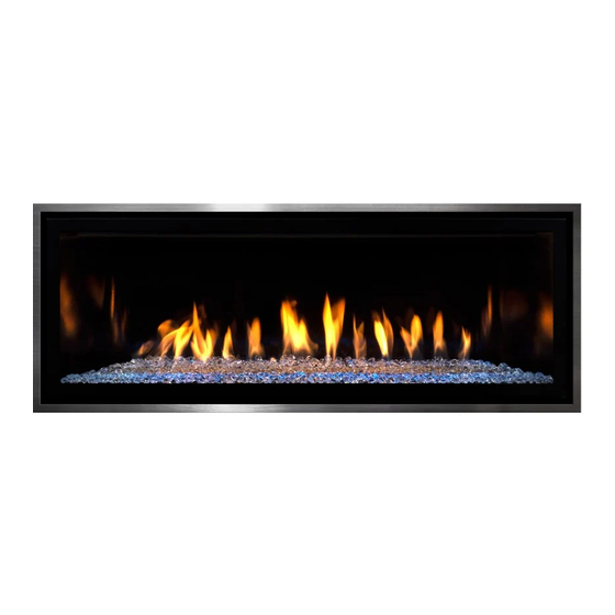
Mendota ML39 Assembly, Installation And Operating Instructions
Fullview direct vent gas fireplace heater
Hide thumbs
Also See for ML39:
- Installation and operating instructions manual (94 pages) ,
- Installation instructions manual (13 pages)
Table of Contents
Advertisement
MODEL NO. ML39 FULLVIEW DIRECT VENT GAS FIREPLACE HEATER
WARNING: If the information in these instructions
is not followed exactly, a fire or explosion may
result causing property damage, personal injury or
loss of life.
- Do not store or use gasoline or other flammable
vapors and liquids in the vicinity of this or any other
appliance.
- WHAT TO DO IF YOU SMELL GAS
•
Do not try to light any appliance.
•
Do not touch any electrical switch; do not
use any phone in your building.
•
Immediately call your gas supplier from a
neighbor's phone. Follow the gas supplier's
instructions.
•
If you cannot reach your gas supplier, call
the fire department.
- Installation and service must be performed by a
qualified installer, service agency or the gas
supplier.
This appliance may be installed in an aftermarket,
permanently located, manufactured home (USA
only) or mobile home, where not prohibited by local
codes.
This appliance is only for use with the type of gas
indicated on the rating plate. This appliance is not
convertible for use with other gasses, unless a
certified kit is used.
A barrier designed to reduce the risk of burns from
the hot viewing glass is provided with this appliance
and must be installed.
Installation and Operating Instructions
85-03-01136
AVERTISSEMENT. Assurez-vous de bien suivre les
instructions données dans cette notice pour réduire au
minimum le risque d'incendie ou d'explosion ou pour
éviter tout dommage matériel, toute blessure ou la mort.
Ne pas entreposer ni utiliser d'essence ni d'autres vapeurs
ou liquids inflammables dans le voisinage de cet appareil
ou de tout autre appareil.
- QUE FAIRE SI VOUS SENTEZ UNE ODEUR DE GAZ:
• Ne pas tenter d'allumer d'appareil.
• Ne touchez à aucun interrupteur. Ne pas vous servir des
téléphones se trouvant dans le bâtiment où vous trouvez.
• Appelez immédiatement votre fournisseur de gaz depuis
un voisin. Suivez les instructions du fournisseur.
• Si vous ne pouvez rejoindre le fournisseur de gaz,
appelez le service des incendies.
- L'installation et l'entretien doivent être assurés par un
installateur ou un service d'entretien qualifié ou par le
fournisseur de gaz.
Cet appareil peut être installé dans une maison
préfabriquée (É.-U. seulement) ou mobile déjà installée à
demeure si les règlements locaux le permettent.
Cet appareil doit être utilisé uniquement avec les types de
gaz indiqués sur la plaque signalétique. Une trousse de
conversion est fournie avec cet appareil.
Une barrière conçue pour réduire le risque de brûlures
du verre chaud est fournie avec cet appareil et doit être
installée.
ML39
Advertisement
Table of Contents

Subscribe to Our Youtube Channel
Related Manuals for Mendota ML39


Summary of Contents for Mendota ML39
- Page 1 Installation and Operating Instructions MODEL NO. ML39 FULLVIEW DIRECT VENT GAS FIREPLACE HEATER WARNING: If the information in these instructions AVERTISSEMENT. Assurez-vous de bien suivre les is not followed exactly, a fire or explosion may instructions données dans cette notice pour réduire au...
- Page 2 HOMEOWNER NOTES 85-03-01136 ML39...
-
Page 3: Initial Firing And Curing Procedure
See chapter Instructions. Read and 3.1.1 Mendota Fireplace Curing follow all instructions given in this Chapter and perform the 3-step curing cycle. After the 3-step curing cycle has been completed, all smoking will have stopped. Some slight odors may remain. With subsequent use of this Fireplace, odors will slowly dissipate and disappear. -
Page 4: Table Of Contents
Table of Contents CAUTION STATEMENTS TO PARENTS OF YOUNG CHILDREN 1.2 INITIAL FIRING AND CURING PROCEDURE ..3 1.3 HOT SURFACES ARE NORMAL ......3 1.4 P ..3 ERIODIC AND ANNUAL CLEANING ARE REQUIRED 2.1 SAFETY AND WARNING INFORMATION ....6 2.2 S .......... - Page 5 5.9 FREQUENTLY ASKED QUESTIONS ..... 74 4.12 L ......65 EDIA NSTALLATION 4.13 L ..........65 IGHTING HECKLIST 4.14 A ..66 HUTTER ONTROL AND LAME PPEARANCE 6.1 R ......78 EQUIRED ERIODIC NSPECTIONS 5.1 A ........67 ESTHETIC ONSIDERATIONS 6.2 C ........
-
Page 6: Safety And Warning Information
Building Permit & Inspection Requirements All installations of Mendota Fireplaces must comply with all the requirements stated in this Installation and Operating Manual. The dealer and/or installer must obtain all required building permits and inspection approvals from the local building inspection department or the local jurisdiction. -
Page 7: Safety Warnings
2.2 SAFETY WARNINGS HIGH-ALTITUDE INSTALLATION INFORMATION: Prior to installing at altitudes higher than 7,500 ft., understand the need for gas input derating. Contact Mendota Technical Service for support. INSTALLER NOTE: These instructions are to remain with homeowner. Be sure to read and understand all instructions carefully before starting the fireplace. Failure to follow these instructions may result in a possible fire hazard leading to property loss, injury or even death and will void all warranty. - Page 8 Never obstruct the flow of combustion and ventilation air. Keep the front of the fireplace clear of all obstacles and materials for servicing and proper operation. Use only Mendota approved Screens, Fronts an d Trim Kits. Due to high temperature, the fireplace should be located out of traffic areas and away from furniture and draperies.
- Page 9 été plongée dans l’eau. Do not use any fronts or doors with this fireplace unless they are certified by Mendota and installed by a certified installer.
-
Page 10: Requirements For Thec
A copy of all installation instructions for all Product Approved side wall horizontally vented gas fueled equipment, all venting instructions, all parts lists for venting instructions, and/or all venting design instructions shall remain with the appliance or equipment at the completion of the installation 85-03-01136 ML39 Page 10... -
Page 11: General Technical References
This fireplace must be installed and serviced by a qualified installer, service agency, or the gas supplier. Any adjustments to burner, pilot, logs or coal bed must be made by a qualified installer, service agency, or the gas supplier. Always use Mendota decorative fronts and Mendota approved vent systems and vent caps only. 85-03-01136... - Page 12 ATTENTION It is important that the blowers are turned on during this step to prevent the curing smoke from staining the wall finish above the fireplace. Mendota recommends completing Step 1 prior to install ation of wall finish materials. Visible smoke and strong odor are to be expected during this step. If desired, disable smoke alarms before this step, smoke from the initial curing c ycle will set off smoke alarms.
-
Page 13: Mechanical Technicalr
WARNING: VENT IS NOT CENTERED ON THE UNIT! Planning the installation This Mendota Fireplace must be installed and serviced by a qualified installer, service agency, or the gas supplier. When planning on appliance installation, it is necessary to determine the following information before installing: •... - Page 14 Listing Label The listing label is located under the firebox. Remove the center access grill and locate the listing plate. It is chained to the firebox’s leg. Figure 3-2 Listing Label 85-03-01136 ML39 Page 14...
- Page 15 Make certain you heed all the warning and caution statements during installation and maintenance of this appliance. Figure 3-4 Figure 3-3 Figure 3-6 Figure 3-5 Figure 3-8 Figure 3-7 Figure 3-9 85-03-01136 ML39 Page 15...
- Page 16 Figure 3-10 Figure 3-11 85-03-01136 ML39 Page 16...
- Page 17 ML39 Fireplace Ratings Information This Mendota Fireplace can be installed directly on top of a metal, masonry or wood structural surface. ELECTRICAL REQUIREMENTS: 120 Volts AC, 1.5 Amps (minimum line voltage allowed 110 Volts AC) REQUIRED GAS SUPPLY PRESSURE: NAT. GAS: 7" W.C. [5.0" W.C. MIN., 11" W.C. MAX.] L.P.
- Page 18 HINT: To greatly reduce surface temperatures surrounding this Fireplace during operation, Mendota recommends operating the integrated convect ion air blowers which aid in cooling all surrounding surfaces. Mendota Fireplaces comply with ANSI Z21.88-2016 Standards for maximum surface temperatures on exposed “combustible” surfaces adjacent to the Fireplace.
- Page 19 Caution: The distance from floor level to the centerline of the vent cap is based on Simpson DuraVent GS components. If using vent components of another brand, do not assume that the measurement given here is applicable. Verify the distance to the centerline of vent cap by measuring the components you are using. 85-03-01136 ML39 Page 19...
- Page 20 Fireplace Features Identification Figure 3-14 FIREPLACE DIMENSIONS AND FEATURES below. Identify the features included with this Fireplace and their locations. WARNING: VENT IS NOT CENTERED ON THE UNIT! Figure 3-14 FIREPLACE DIMENSIONS AND FEATURES 85-03-01136 ML39 Page 20...
- Page 21 Convection Blower System Dual blowers are provided as standard equipment with this ML39 Fireplace. The dual blowers have an air output rating of 190 CFM (in free air). This Fireplace is designed to operate with the blowers turned off or on. Turning the blower on aids in distributing and circulating heat to the room this Fireplace is installed in.
- Page 22 If the fireplace is to be recessed in a cavity deeper than 22”, all framing and finishing materials protruding past the front face of this fireplace must be of the NON-COMBUSTIBLE variety. WARNING: VENT IS NOT CENTERED ON THE UNIT Figure 3-16 FRAMING DIMENSIONS 85-03-01136 ML39 Page 22...
- Page 23 WARNING: VENT IS NOT CENTERED ON THE UNIT! Figure 3-17 Floor to Wall Thimble Center Dimension 85-03-01136 ML39 Page 23...
- Page 24 WARNING: VENT IS NOT CENTERED ON THE UNIT! If the required clearance cannot be m et to a pre-existing combustible side wall, an NFPA approved clearance reduction shield, metal or ceramic board, must be added to the s ide wall. 85-03-01136 ML39 Page 24...
- Page 25 (Depth of Mantel) – 8” + 51” = (Height above the floor of the fireplace) 12” – 8” + 51” = 55” DO NOT deviate from this minimum clearance requirement. Doing so can lead to a severe fire hazard. Figure 3-19 Mantel Clearances 85-03-01136 ML39 Page 25...
- Page 26 Suitable Mantel and Facing Materials Use of ceramic glazed tiles as facing materials around a Mendota Fireplace is approved. Use caution when selecting tile adhesives. Avoid premixed tile adhesives which contain products that can off gas for long periods when exposed to heat. Use Portland cement based unmixed tile adhesives or RTV Silicone to attach ceramic glazed tiles as facing in hot areas around this Fireplace.
- Page 27 Mendota Fireplaces. Mendota further cautions that proper adhesives be used to attach stone facings. Pay attention to the potential of off-gassing of chemical vapors from mastic and other adhesives. Improper selection can lead to emission of chemicals with unwanted smells.
-
Page 28: Paint Types Approved For Use
Always select the lowest moisture content wood substrate. Refer to Mendota Fireplace Curing Instructions, Chapter 3.1.1. FRAMING DEPTH and FINISHING GUIDES This fireplace comes with one standard finishing guide that will be used with any inside finish decorative front. - Page 29 There are three options for finishing the fireplace when installing a Grace front. Please read the following instruction before installing the finishing material on the front of this fireplace. If you have any questions about finishing the fireplace, contact a Mendota dealer or the Mendota Service Department. •...
- Page 30 This option allows the front to mount with any finish material. It is a “recessed” or “flush” finish. Use the reference chart or pricing sheets to see which guide kit is required for each decorative front type. 85-03-01136 ML39 Page 30...
- Page 31 Note: The model depicted in the images in this document may not match the particular model you have selected. However, these instructions do apply commonly to all Mendota ZC Fireplaces. All flat panel TVs are solid state electronic appliances and are vulnerable to high ambient temperatures.
- Page 32 However, the installed TV’s bottom edge must be 24” (minimum) above the top edge of the top air gap of this fireplace. Three Cool Wall Kit options are available. Depending on the room ceiling height and TV size, select a suitable Cool Wall Kit. OPTION 3- SIDE VIEW 85-03-01136 ML39 Page 32...
- Page 33 The ML39 Fireplaces requires coaxial rigid- 5” diameter exhaust & 8” diameter air inlet and approved vent caps for most installations. In some special cases, flexible ducting may be used. Contact Mendota Technical Service Department if your installation requires other than standard rigid 5”...
- Page 34 Flue Venting Components Identification Diagrams Prior to installing at altitudes higher than 7500, please contact the Mendota technical service department for specific venting requirements and venting restrictions. ITEM DESCRIPTION 6" or 7” PIPE (DuraVent 6”/Amerivent 7”), 9”, 12” 12" VENT STACK 24"...
- Page 35 DUAL 90° ELBOWS VERTICAL TERMINATION ZERO VERTICAL DUAL 90° ELBOWS VERTICAL TERMINATION NOT ALLOWED APPROVED APPROVED VERTICAL RISE THREE HORIZONTAL DISCHARGE TRIPLE 90° ELBOWS 90° ELBOWS VERTICAL TERMINATION VERTICAL RISE TRIPLE 90° ELBOWS HORIZONTAL TERMINATION APPROVED APPROVED APPROVED 85-03-01136 ML39 Page 35...
- Page 36 (45 cm) minimum ‡) Clearance to inside corner - 12 inches (30 cm). Minimum 24” horizontal clearance to any surface, Vinyl surfaces require 24” min (60 cm). such as an exterior surface, for vertical terminations. 85-03-01136 ML39 Page 36...
- Page 37 Alternatively, you may also vertically extend the wood burning flue liner up 24” higher than the top surface of the gas appliance vent cap. Figure 3-25 Side by Side Vent Caps 85-03-01136 ML39 Page 37...
- Page 38 Decorative Cover for Vent Cap It is acceptable to install a decorative stone, metal or terra cotta cover to disguise the vent terminal/cap used on Mendota Fireplaces if the decorative cover meets the following minimum requirements: The decorative cover shall be manufactured from noncombustible materials.
-
Page 39: Eferences
Once the wire is plugged in, place the wire into the junction box and reinstall the cover plate. STEP 1 STEP 2 STEP 3 Figure 3-28 Wire Connections 85-03-01136 ML39 Page 39... - Page 40 Instruct homeowner to retain the DC battery pack and the connecting harness in a safe and secure place for use during power outages Figure 3-30 BACKUP DC POWER INLET Figure 3-29 Backup DC Power Junction Box Installation Figure 3-31 DC Backup Power Connection 85-03-01136 ML39 Page 40...
- Page 41 Label all wires prior to disconnection when servicing not installed nor used. control. Wiring Errors can cause improper and dangerous Replacement wires must have the same type and size of operation. Verify proper operation after servicing. insulation as the original. 85-03-01136 ML39 Page 41...
-
Page 42: Lumbing Technical References
TRAIN. ADHERE STRICTLY TO LOCAL AND NATIONAL CODES. Gas Supply Line Sizing This Mendota Gas Fireplace comes equipped with a 1/2" N.P.T. Female inlet. Gas supply piping must enter the Fireplace cabinet on the right side. Use the table, below, to determine the proper gas line diameter that must be installed to run from the supply regulator to the fireplace. - Page 43 If local building codes require one, obtain an external keyed wall-mounted or floor-mounted manual gas shutoff valve approved per local gas plumbing codes and install per local gas plumbing codes in the specified location. Local requirements supersede all other codes. Figure 3-35 Keyed Manual Gas Shutoff Valve 85-03-01136 ML39 Page 43...
- Page 44 The gas inlet fitting supplied with this Fireplace provides a 1/2” female NPT fitting. This requires you to supply a ½” NPT male fitting for connection to this appliance. Based on the gas line size you have selected use an appropriate NPT fitting to adapt and connect to the 1/2” male NPT flex end adapter. 85-03-01136 ML39 Page 44...
- Page 45 This appliance has been converted for use at an altitude of: Orifice size: Manifold Pressure: Input (Btu/h): Fuel Type: Date of conversion: Converted by: Cet appreeil a été converti au ____ Injecteur ________ Pression à la tubulure d'alimentation _____________ Déoit calorifique ______________ 85-03-01136 ML39 Page 45...
-
Page 46: Installation Checklist
❑ Adjust vent damper to match vertical chimney length. See 4.11.1 Vent Damper Adjustments ❑ Co-axial vent rigid pipe, wall vent cap or roof vent cap is installed by a Mendota approved serviceperson in accordance with instructions. ❑ All joints are secured, "twist-locked" and leak-proof. -
Page 47: Unpacking The Fireplace
Lift the outer box vertically straight upward until lower edge of the box clears the top of the unit body. Set the box aside. Mendota recommends recycling the outer box. Figure 4-1 Outer Box Removal 85-03-01136... -
Page 48: Contents Of The Manual Packet
Once the outer box is removed, you will find the Fireplace body and a manual packet white box. This manual packet white box includes the items shown in the table, below. Contact Mendota Technical Service if any parts are missing. -
Page 49: Ending Up The Shipping Clips
3. Remove screw driver. Fireplace screw driver tip into one hole in clip. Lift screw driver up. To break clip off, repeat up down motion of screw driver seven to eight times. Figure 4-4 Shipping Clip STEP 1 & STEP 2 STEP 3 Figure 4-6 Bend Up Clip 2 Figure 4-5 Bend Up Clip 1 85-03-01136 ML39 Page 49... -
Page 50: O Remove Door
Use the tool provided to connect the spring latches to the glass frame. Fireplace tool into hole in spring latch, pull latch towards you, rotate latch so the hook is facing downward then release latch to hook to door frame. Door is now connected and sealed to unit. 85-03-01136 ML39 Page 50... -
Page 51: Nstallation
3. Next, see diagrams, below. Install the light lens base gasket, light lens, light lens retainer bracket and the four retaining 10-24 nuts. Warning: Use a 3/8” hex hand driver to tighten nuts.DO NOT over tighten the nuts. Doing so can crack the light lens. Figure 4-8 Accent Light Bulb & Lens Installation 85-03-01136 ML39 Page 51... -
Page 52: Natural Gas To Lpg Conversion
Then hold the floor plate at an angle to get it through the front opening of the fireplace. 3. Using a ¼” hex driver, remove the right-side front access panel from the fireplace. 85-03-01136 ML39 Page 52... - Page 53 When removing and installing the orifices be sure to use a wrench to keep the fitting the orifice screws onto from rotating. 6. Thread a new #50 orifice on the orifice mounting brass fittings. Tighten down the orifice. Next continue to follow the instructions to convert the pilot for LP Gas. 85-03-01136 ML39 Page 53...
- Page 54 12. Shut off the gas supply to the valve and shut down the electric supply. Note: Be careful when removing or tightening the screw on the back of the pressure regulator. The screw location is difficult to access, and care must be taken to ensure a proper seal when tightened. 85-03-01136 ML39 Page 54...
- Page 55 Warning: Correct operation of the system cannot be guaranteed if the conversion kit or value have been Figure 4-13 Pressure Regulator Conversion dropped or sustained strong impact. 85-03-01136 ML39 Page 55...
- Page 56 Verify that the burner tubes ignite quickly and the burner flames propagate smoothly along the entire length of the burners. 1" MIN. 1" MIN. Pilot Flame and Burner Ports Figure 4-14 Pilot Flames 85-03-01136 ML39 Page 56...
-
Page 57: Venting
Fireplace to a chimney flue serving a se parate solid fuel or gas-burning appliance. The ML39 Fireplace must be vented to the outside and must use one of the approved coaxial rigid ducting Do Not Use any silicone sealants at pipe joints. Stove systems or a coaxial flexible ducting system . - Page 58 ML39 Master Venting Chart Note: This chart is applicable to both natural gas and LP installations. ❑ 9” minimum vertical pipe run required to be connected directly to this fireplace’s flue starter collar. ❑ Maximum horizontal run allowed with the minimum 9” vertical run is 12”.
- Page 59 Using 90 Elbows The ML39 Fireplace by MENDOTA allows maximum flexibility in the use of 90 elbows in the vent system. The length of the first straight vertical section directly connected to the fireplace’s starter collar determines the maximum horizontal run and the number of 90 elbows allowed for this fireplace.
- Page 60 From the exterior of the home, slide the horizontal vent cap over the end of the horizontal pipe and tightly secure the cap to the wall with screws. Seal with a high-quality caulking. NOTE: Combustible wall thickness must be 4" to 8" maximum NOTE: Vent Cap should not be recessed into wall or siding. 85-03-01136 ML39 Page 60...
- Page 61 Note: Vent cap should not be recessed into wall or siding. Vertical Rise Three 90° Elbows Horizontal Termination Use the Master Venting Chart to calculate allowable lengths. 85-03-01136 ML39 Page 61...
- Page 62 Height "*H" from roof surface to the top of vent cap can be determined as follows: Complete installation with storm collar and vent cap. "H" DIMENSION ROOF PITCH FEET METERS FLAT to 6/12 7/12 to 9/12 10/12 to 12/12 13/12 to 16/12 17/12 to 21/12 85-03-01136 ML39 Page 62...
- Page 63 Mendota has spent considerable time and effort in the design of this fireplace and its venting system. Through this effort, Mendota has been able to certify the use of Four 90 elbows.
- Page 64 1/8” and turn clockwise to close the vent damper, release. The base of the damper adjustment rod has a pointer that indicates the position of the damper. 85-03-01136 ML39 Page 64...
-
Page 65: Log Set/ Media Installation
☐ DO NOT proceed with operation unless burner cycles "on/off" without delays and the flame is "stable" and not "lifting" off burner after 5 minutes of initial ignition. Caution: If ignition system goes into lockout mode , be sure to wait a minimum of five minutes before relighting. 85-03-01136 ML39 Page 65... -
Page 66: Lame Appearance
Also, if a log or part of a log is suspended and hanging inside a yellow portion of the flame, soot can form easily on the part of the log that is inside the yellow flame area. IMPORTANT: Try each new shutter setting approx. ½ hr. before mak ing additional changes. 85-03-01136 ML39 Page 66... -
Page 67: Aesthetic Considerations
We are committed to quality and satisfaction for all Mendota owners. Thank you for choosing a Mendota to be a source of comfort and beauty in your home. -
Page 68: Operating Information
Using Your Remote Control Your Mendota remote control is pre-programmed to your fireplace. Ensure you have installed 3 AAA batteries into your remote. Press the top button on the remote control. If you do not hear a beep when you press this button, follow the instructions below to synchronize your fireplace and remote control. - Page 69 3. Up/Down Button: This button is used to increase or decrease the thermostat temperature, flame height, fan speed, and accent light intensity. Mode Selection Button: This button is used to toggle between the various function icons: flame height, fan speed, accent light. 85-03-01136 ML39 Page 69...
-
Page 70: Remote Control Operating
Understanding Your Remote-Control Icons Your remote control displays and controls the following functions. See below for detailed control explanations. Note: the “AUX On” and “Rear Burner” functions are not used in this fireplace. Figure 5-2 Remote Control Icons 85-03-01136 ML39 Page 70... -
Page 71: Elsius To Fahrenheit
Press the ON/OFF button and turn off the fireplace. Simultaneously, press both the mode button and the thermostat button. ° ° Look at the LCD display to verify that your desired indicator ( F or C) is being displayed. If not, repeat Step 2. 85-03-01136 ML39 Page 71... -
Page 72: Ipi And Cpi Modes
Note: The snowflake icon will be visible on the display at all times when in CPI mode. Recommended: Mendota recommends that CPI mode is used during the winter months ° when the average daily high temperature falls below 50 F. - Page 73 3. Turn OFF the external manual shutoff valve if was required and supplied by installer and mounted adjacent to fireplace. 4. Turn OFF the internal manual shutoff valve located in the fireplace under the front right access panel. 5. Turn OFF all electric power to the fireplace if service is to be performed. 85-03-01136 ML39 Page 73...
-
Page 74: Frequently Asked Questions
Where can I find the model and serial numbers? When requesting service, you will be asked to provide the model number and serial number to your Mendota dealer. This information will expedite the warranty verification process. The Listing Label contains the model number and serial number for your particular appliance. - Page 75 3” to 12” long area) and the gasket adhesive in no longer functional to stick to glass, then replace the gasket. Visually inspect the vent terminal (vent cap) for leaves, twigs and other debris accumulation. Clean if required. Clean door glass. 10. Clean enamel firebox lining, if one is installed. 85-03-01136 ML39 Page 75...
- Page 76 These adjustments should be made by a qualified technician to achieve the best flame performance. Contact your installer or Mendota dealer if you feel your fireplace is not burning correctly. Improper setup and adjustment is not covered under warranty.
- Page 77 This should clear the lockout mode. Turn on the remote and start the fireplace. Ensure the master switch is in the run/on position. After completing these steps, contact your Mendota dealer if fireplace won’t turn on. What happens when I first light my fireplace? When you first light your fireplace, the initial curing phase is initiated.
-
Page 78: Required Periodic Inspections
Check glass gasket seal. Visually inspect glass gasket, especially at the corners of the glass piece. Glass gasket is installed as a 4- piece assembly. Check joints between the gasket pieces at the corners. They should butt against each other to create a seal. Gaps between gasket pieces can cause exhaust leaks and lead to acrid smell concerns. 85-03-01136 ML39 Page 78... - Page 79 If you are using a “backyard” Natural Gas well as the gas source, you must submit formal gas analysis data sheets to Mendota Fireplaces f or review and calculation of proper main burner orifice sizes prior to first firing. It is known that unpurified Natural Gas from “backyard” wells can contain high energy levels causing over firing.
-
Page 80: Replacement Parts Information
Control Board: The control board is mounted on the right side of the fireplace. To access the control board, remove the right- side access panel and heat shield from the fireplace. The board is Velcroed to the floor simply pull up on the board to remove it from the fireplace. 85-03-01136 ML39 Page 80... - Page 81 Accent Light: The accent lights are mounted in the firebox top. The lens and retaining bracket is held on with 4 nuts. Convection Air Blower System Parts Figure 6-3 ML39 BLOWER ASSEMBLIES 85-03-01136 ML39...
- Page 82 Accent Light Parts HA-58-04606 ACCENT LIGHT HOUSING 10-11-00020 LIGHT BULB, G9 XENON, 25W 10-11-00025 ACCENT LIGHT LENS-2016 HA-88-00168 LENS RETAINER BRACKET WITH GASKET HA-77-00357 LIGHT COVER CLIP Figure 6-4 ML39 Light Assembly Parts Gas Train Assembly Parts 85-03-01136 ML39 Page 82...
- Page 83 The glass frame assembly and its individual components are available through Johnson Gas Appliance Company. Contact your dealer for more detailed ordering information. GLASS FRAME ASSEMBLY REPLACEMENT PARTS LIST ITEM PART NUMBER DESCRIPTION GLASS FRAME, WELDMENT, ML39 HA-96-00053 GASKET, TADPOLE, 5 /8” BULB, 3/4” TAIL 65-02-00103 65-06-01367 GLASS, CERAMIC, ML39...
-
Page 84: Nstaller Erification Hecklist
WARRANTY QUALIFICATION AND SERVICE The following information verifies proper installation and operation of your Mendota Fireplace. All installation and operating instructions must be carefully followed. This Mendota Fireplace must be installed and serviced by a qualified installer, service agency, or the gas supplier. -
Page 85: Warranty Policy Statement
7.2 WARRANTY POLICY STATEMENT Mendota Fireplace, a division of Johnson Gas Appliance Company, extends this Limited Lifetime Warranty to the original purchaser of this appliance provided the product remains in the original place of installation. The items covered by this limited warranty and the period of such coverage is set forth in the table below. - Page 86 Owner accepts that this appliance requires close monitoring of children and vulnerable individuals who are in the vicinity of this appliance when it is in operation. Mendota does not assume or accept any liability claims for burns or other physical or material damages resulting from touching hot glass surface and hot metal surfaces that are part of this appliance or other adjacent object such as hearth pads and mantels that may heat up during operation of this appliance.
- Page 87 How to Obtain Warranty Service If you discover a problem that you believe to be covered by the warranty, you must report to your Mendota Dealer within 30 days, with proof of purchase, purchase date, model name and serial number.
- Page 88 Owner Registration After installation, Mendota fireplace owners must register with Mendota to qualify for the Lifetime Limited Warranty within 30 days. Product registration will activate your Lifetime Limited Warranty. Owners should complete the forms available at: http://mendotahearth.com/gas-fireplace-and-stove-registration.php Note: Your Mendota dealer can assist with warranty applications and information.
- Page 89 Thank you for choosing Mendota.
- Page 90 Johnson Gas Appliance Company 520 E Avenue NW Cedar Rapids, Iowa 52405 Mendota Warranty Registration...
Need help?
Do you have a question about the ML39 and is the answer not in the manual?
Questions and answers