Table of Contents
Advertisement
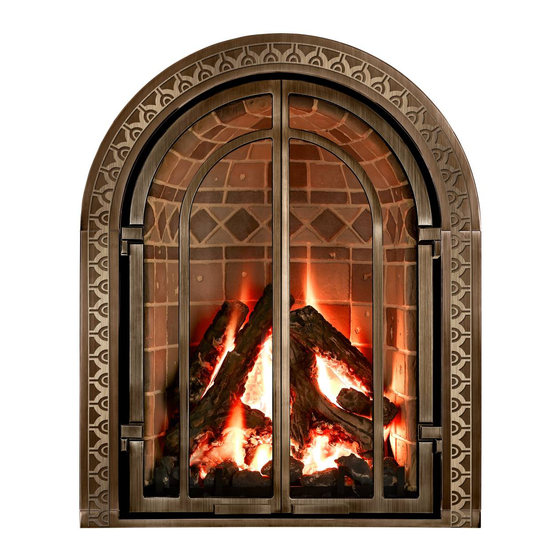
MODEL NO. M27 OPEN HEARTH DIRECT VENT GAS FIREPLACE HEATER
WARNING: If the information in these instructions
is not followed exactly, a fire or explosion may
result causing property damage, personal injury or
loss of life.
- Do not store or use gasoline or other flammable
vapors and liquids in the vicinity of this or any other
appliance.
- WHAT TO DO IF YOU SMELL GAS
•
Do not try to light any appliance.
•
Do not touch any electrical switch; do not
use any phone in your building.
•
Immediately call your gas supplier from a
neighbor's phone. Follow the gas supplier's
instructions.
•
If you cannot reach your gas supplier, call
the fire department.
- Installation and service must be performed by a
qualified installer, service agency or the gas
supplier.
This appliance may be installed in an aftermarket,
permanently located, manufactured home (USA
only) or mobile home, where not prohibited by local
codes.
This appliance is only for use with the type of gas
indicated on the rating plate. This appliance is not
convertible for use with other gasses, unless a
certified kit is used.
A barrier designed to reduce the risk of burns from
the hot viewing glass is provided with this appliance
and must be installed.
Installation and Operating Instructions
85-03-01120-C
AVERTISSEMENT. Assurez-vous de bien suivre les
instructions données dans cette notice pour réduire au
minimum le risque d'incendie ou d'explosion ou pour
éviter tout dommage matériel, toute blessure ou la mort.
Ne pas entreposer ni utiliser d'essence ni d'autres vapeurs
ou liquids inflammables dans le voisinage de cet appareil
ou de tout autre appareil.
- QUE FAIRE SI VOUS SENTEZ UNE ODEUR DE GAZ:
• Ne pas tenter d'allumer d'appareil.
• Ne touchez à aucun interrupteur. Ne pas vous servir des
téléphones se trouvant dans le bâtiment où vous trouvez.
• Appelez immédiatement votre fournisseur de gaz depuis
un voisin. Suivez les instructions du fournisseur.
• Si vous ne pouvez rejoindre le fournisseur de gaz,
appelez le service des incendies.
- L'installation et l'entretien doivent être assurés par un
installateur ou un service d'entretien qualifié ou par le
fournisseur de gaz.
Cet appareil peut être installé dans une maison
préfabriquée (É.-U. seulement) ou mobile déjà installée à
demeure si les règlements locaux le permettent.
Cet appareil doit être utilisé uniquement avec les types de
gaz indiqués sur la plaque signalétique. Une trousse de
conversion est fournie avec cet appareil.
Une barrière conçue pour réduire le risque de brûlures
du verre chaud est fournie avec cet appareil et doit être
installée.
M27
Advertisement
Table of Contents

Related Manuals for Mendota M27


Summary of Contents for Mendota M27
- Page 1 Installation and Operating Instructions MODEL NO. M27 OPEN HEARTH DIRECT VENT GAS FIREPLACE HEATER WARNING: If the information in these instructions AVERTISSEMENT. Assurez-vous de bien suivre les is not followed exactly, a fire or explosion may instructions données dans cette notice pour réduire au...
- Page 2 HOMEOWNER NOTES 85-03-01120 Page 2...
-
Page 3: Hot Surfaces Are Normal
See chapter Instructions. Read and 3.1.1 Mendota Fireplace Curing follow all instructions given in this Chapter and perform the 3-step curing cycle. After the 3-step curing cycle has been completed, all smoking will have stopped. Some slight odors may remain. With subsequent use of this Fireplace, odors will slowly dissipate and disappear. -
Page 4: Table Of Contents
1.3 H ........3 URFACES ARE ORMAL 2.1 SAFETY AND WARNING INFORMATION ....6 3.2.15.3.1 Mendota Cool Wall ..Error! Bookmark not defined. 3.2.15.3.2 Versiheat ..Error! Bookmark not defined. 3.2.15.3.3 FlexHeat ..Error! Bookmark not defined. 2.2 S ..........7... - Page 5 4.13 V ............57 ENTING 6.1 R ......92 EQUIRED ERIODIC NSPECTIONS 6.2 C ........92 LEANING IEWING LASS 6.3 R ......92 EQUIRED NNUAL AINTENANCE 6.4 O ....93 IRING OR NDER IRING OF URNER 6.5 PILOT OUTAGE ......93 IGHTING 6.6 COMBUSTION SYSTEM MILLIVOLT READINGS ...
-
Page 6: Safety And Warning Information
Building Permit & Inspection Requirements All installations of Mendota Fireplaces must comply with all the requirements stated in this Installation and Operating Manual. The dealer and/or installer must obtain all required building permits and inspection approvals from the local building inspection department or the local jurisdiction. -
Page 7: Safety Warnings
HIGH-ALTITUDE INSTALLATION INFORMATION: Prior to installing at altitudes higher than 7,500 ft., understand the need for gas input derating. Contact your local gas company to see if your gas type is already derated for your altitude or contact Mendota Technical Service for support. - Page 8 Never obstruct the flow of combustion and ventilation air. Keep the front of the fireplace clear of all obstacles and materials for servicing and proper operation. Use only Mendota approved Screens, Fronts and Trim Kits. Due to high temperature, the fireplace should be located out of traffic areas and away from furniture and draperies.
- Page 9 été plongée dans l’eau. Do not use any fronts or doors with this fireplace unless they are certified by Mendota and installed by a certified installer.
-
Page 10: Requirements For Thec
2.3 REQUIREMENTS FOR THE COMMONWEALTH OF MASS. The information in this section applies to all installations performed in the Common Wealth of Massachusetts only. For all side wall, horizontally vented gas fueled equipment installed in every dwelling, building or structure used in whole or in part for residential purposes and where the side wall exhaust vent termination is less than seven (7) feet above grade, the following requirements shall be satisfied: 1. -
Page 11: General Technical References
If the ignition control system goes into lockout mode, always wait 5 minutes before attempting to relight. Never block off convection air openings or paths. Trim panels or surrounds shall not seal ventilation openings in the fireplace. Always use Mendota decorative fronts and Mendota approved vent systems and vent caps only. Keep the flue warm It is required to leave the pilot light running during winter months when outside daily high temperatures remain 50 F or lower. - Page 12 ATTENTION It is important that the blowers are turned on during this step to prevent the curing smoke from staining the wall finish above the fireplace. Mendota recommends completing Step 1 prior to install ation of wall finish materials. Visible smoke and strong odor are to be expected during this step. If desired, disable smoke alarms before this step, smoke from the initial curing c ycle will set off smoke alarms.
-
Page 13: Mechanical Technicalr
3.2 MECHANICAL TECHNICAL REFERENCES Planning the installation This Mendota Fireplace must be installed and serviced by a qualified installer, service agency, or the gas supplier. When planning on appliance installation, it is necessary to determine the following information before installing: •... - Page 14 Listing Label The listing label is located behind the right side hinged surround leg.. It is secured to a chain and left loosely in the air gap and can be pulled out to be viewed. Figure 3-1 Listing Label 85-03-01120 Page 14...
- Page 15 Other Warning and Caution Labels A few warnings and caution labels are attached to this appliance body and door glass as required per code to inform you of important facts. Make certain you heed all the warning and caution statements during installation and maintenance of this appliance.
- Page 16 Figure 3-7 Figure 3-8 85-03-01120 Page 16...
- Page 17 M27 Fireplace Ratings Information This Mendota Fireplace can be installed directly on top of a metal, masonry or wood structural surface. ELECTRICAL REQUIREMENTS: 120 Volts AC, 1.5 Amps (minimum line voltage allowed 110 Volts AC) REQUIRED GAS SUPPLY PRESSURE: NAT. GAS: 7" W.C. [5.0" W.C. MIN., 11" W.C. MAX.] L.P.
- Page 18 HINT: To greatly reduce surface temperatures surrounding this Fireplace during operation, Mendota recommends operating the integrated convection air blowers which aid in cooling all surrounding surfaces. Mendota Fireplaces comply with ANSI Z21.88-2016 Standards for maximum surface temperatures (ambient plus 117 F) on exposed “combustible”...
- Page 19 Fireplace Dimensions and Clearances Figure 3-10 Overall Fireplace Dimensions 85-03-01120 Page 19...
- Page 20 Rough Framing Dimensions The Rough Framing Height must be maintained to allow this fireplace and the 90-degree elbow connected directly to the top, on certain vent systems, to slide into the framing cavity. Once the fireplace is positioned inside the framed cavity, a secondary nailer stud should be added at a minimum height of 38 inches above the floor level of this fireplace.
- Page 21 Constructing the Appliance Chase A chase is a vertical box-like structure built to enclose this fireplace and its vent system. Vertical vents that run on the outside of a building may be, but are not required to be, installed inside a chase. Construction of the chase may vary with the type of building.
- Page 22 Clearance from Appliance Outer Surfaces Figure 3-14 CLEARANCES TO APPLIANCE BODY 85-03-01120 Page 22...
- Page 23 Clearances to Combustible Side Walls The minimum distance required from the side edge of the visible glass to a combustible side wall is 12”. Combustible side walls, mantel corbels, mantel legs and other combustible walls and decorative objects must fall behind a 45-degree line extending outward from the side edges of the visible glass unless such objects are more than 12”...
- Page 24 Clearances to Combustible Mantels An 8” combustible mantel may be installed at a minimum of 13" above the top of the heat outlet (47” up from the floor level of this Fireplace). Non-combustible (marble, brick, stone, metal etc.) mantels can be installed at any desired height above the top convection air opening.
- Page 25 Hearth Pad Requirement A non-combustible hearth protector with a thermal insulation rating of R-1 is required when installing this fireplace directly on the floor and must extend a minimum of 12" in front of this fireplace. For every 1” the fireplace is raised off the floor, the depth of the required hearth protector may be r educed by 2”.
- Page 26 Suitable Mantel, Facing & Hearth Pad Materials Use of ceramic glazed tiles as facing materials around a Mendota Fireplace is approved. Use caution when selecting tile adhesives. Avoid premixed tile adhesives which contain products that can off gas for long periods when exposed to heat. Use Portland cement based unmixed tile adhesives or RTV Silicone to attach ceramic glazed tiles as facing in hot areas around this Fireplace.
- Page 27 Mendota Fireplaces. Mendota further cautions that proper adhesives be used to attach stone facings. Pay attention to the potential of off-gassing of chemical vapors from mastic and other adhesives. Improper selection can lead to emission of chemicals with unwanted smells.
-
Page 28: 5.1Paint Types Approved For Use
Moisture content of the wood substrate is also of critical importance. High moisture content wood when heated will yield evaporation of the moisture and hydraulic pressure under the paint or sealants which can lead to peeling or bubbling. Always select the lowest moisture content wood substrate. Refer to Mendota Fireplace Curing Instructions, Chapter 3.1.1. 85-03-01120 Page 28... -
Page 29: Figure
FRAMING DEPTH and FINISHING MATERIAL THICKNESS The nominal framing depth for this fireplace is 14 inches. except for a corner installation and for installations that use solid Granite or Marble slabs as fascia materials. The framing depth may be left at 14” deep or reduced based on the finishing material thickness. -
Page 30: Figure
Finishing Materials Cutting Dimensions Figure 3-21 FINISHING MATERIALS CUTTING DIMENSONS 85-03-01120 Page 30... - Page 31 Many television manufacturers specify in their installation instructions that the television must not be installed near or above a heat source. The decision to install a television near or above a Mendota fireplace rests solely on the consumer. It is the consumers responsibility to satisfy television specifications and insure the television will not exceed maximum operation temperatures.
- Page 32 Recommendation 2: Create a recessed cavity Frame a recessed cavity above the fireplace. The cavity shall be at least 6 inches taller and 6 inches wider than the television. The cavity’s bottom surface must be a minimum of 24 inches above the top air gap of this fireplace. The cavity must be deep enough for the television to be recessed at least 2 inches in from the wall.
-
Page 33: Rocedure
The M27 Fireplaces requires coaxial rigid- 4” diameter exhaust & 6-5/8” diameter air inlet and approved vent caps for most installations. In some special cases, flexible ducting may be used. Contact Mendota Technical Service Department if your installation requires other than standard rigid 4”... - Page 34 Flue Venting Components Identification Diagrams Prior to installing at altitudes higher than 7500, please contact the Mendota technical service department for specific venting requirements and venting restrictions. ITEM DESCRIPTION 6" or 7” PIPE (DuraVent 6”/Amerivent 7”), 9”, 12” 12" VENT STACK 24"...
- Page 35 Approved Vent Systems 85-03-01120 Page 35...
- Page 36 Exterior Vent Locations and Restrictions Note: All measurements are to be taken from the center of the vent cap. - - Air Supply Inlet Vent Terminal Area where terminal is not permitted Clearance above grade, veranda, porch, deck, or *Not to be installed above a meter/regulator assembly balcony (*18 inches (45 cm) minimum) within 3 feet (90 cm) horizontally from the center-line...
- Page 37 Side by Side installation of two Vent Caps When two or more vertical vent caps are located within proximity of one another, it is required that a galvanized steel 18-gauge or heavier barrier wall be installed between the two vent caps to eliminate recirculation of exhaust gases from one cap to another.
- Page 38 Decorative Cover for Vent Cap It is acceptable to install a decorative stone, metal or terra cotta cover to disguise the vent terminal/cap used on Mendota Fireplaces if the decorative cover meets the following minimum requirements: The decorative cover shall be manufactured from noncombustible materials.
-
Page 39: Eferences
ELECTRICAL TECHNICAL REFERENCES AC Power Requirements WARNING: Label all wires prior to disconnection when servicing controls. Wiring errors can cause improper and dangerous operation. Verify proper operation after servicing. For operation of the blowers, this appliance requires 120 VAC, 2 Amp power source. The AC power supply to this Fireplace must be hot at all times and shall not have a switch installed in it. - Page 40 Convection Blower System Dual blowers are provided as standard equipment with this M27 Fireplace. The dual blowers have an air output rating of 190 CFM (in free air). This Fireplace is designed to operate with the blowers turned off or on. Turning the blower on aids in distributing and circulating heat to the room this Fireplace is installed in.
-
Page 41: Lumbing Technical References
TRAIN. ADHERE STRICTLY TO LOCAL AND NATIONAL CODES. Gas Supply Line Sizing This Mendota Gas Fireplace comes equipped with a 1/2" N.P.T. Female inlet. Gas supply piping must enter the Fireplace cabinet on the left side. Use the table, below, to determine the proper gas line diameter that must be installed to run from the supply regulator to the factory installed manual shutoff valve. - Page 42 Gas Pressure Requirements and Checking Two pressure taps for checking input and output gas pressures are located on the main gas valve. A qualified installer should use this fitting for setting the correct gas pressure during initial installation. The appliance and its appliance main gas valve must be disconnected from the gas supply piping system during any pressure testing of that system at test pressures in...
- Page 43 Factory Installed Manual Gas Shutoff Valve A manual gas shutoff valve is factory installed and located in the left-side above the main gas valve. To operate the manual gas shutoff, open left side door to expose controls. Located manual gas shutoff handle. Rotate clockwise to shut off gas flow or counter-clockwise to turn on gas flow.
- Page 44 Gas Input Rate Verification Natural Gas Input Rate Verification Verify main orifice size. The main orifice body has the orifice hole size stamped on it. NG orifice size shall be #45 (rear burner) and #51 (front burner) for all elevations in between 0-2000ft. NG orifice size shall be #46 (rear burner) and #52 (front burner) for all elevations exceeding 2000ft.
-
Page 45: Installation Checklist
❑ Adjust exhaust damper to match vertical chimney length. See 4.13.12 Vent Damper Adjustments ❑ Co-axial vent rigid pipe, wall vent cap or roof vent cap is installed by a Mendota approved serviceperson in accordance with instructions. ❑ All joints are secured, "twist-locked" and leak-proof. -
Page 46: Unpacking The Fireplace
Lift the outer box vertically straight upward until lower edge of the box clears the top of the unit body. Set the box aside. Mendota recommends recycling the outer box. Figure 4-1 Outer Box Removal 85-03-01120... -
Page 47: Contents Of The Manual Packet
Once the outer box is removed, you will find the Fireplace body and a manual packet white box. This manual packet white box includes the items shown in the table, below. Contact Mendota Technical Service if any parts are missing. -
Page 48: Unbolting Fireplace From Pallet
4.6 UNBOLTING FIREPLACE FROM PALLET The Fireplace body is bolted to the pallet top surface using 5/16” X 1” Lag Screws in three points. One on each side and one or more at the rear. Use a 1/2” socket and wrench to remove the lag screws and detach fireplace from the pallet top. Figure 4-3 Unbolting Unit from Pallet 85-03-01120 Page 48... -
Page 49: O Remove Door
4.8 TO REMOVE DOOR Use the glass latch tool to disconnect the spring latches from the glass frame. Insert tool into hole in latch, pull towards you and rotate 180-degrees to disengage top latches. Remove tool. There are four spring latches on this gas fireplace. Always make certain the hook glass latches are in the inverted position after removing the glass frame. -
Page 50: T Oreplace Door
4.10 TO REPLACE DOOR Line up the two bottom tabs in glass frame bottom with two slots in the glass clips located at the bottom of firebox. Insert tabs into slots and center tabs in slots, left to right. Center glass frame over firebox; left to right. After door has been placed into slots, rotate door towards firebox until gasket seal is touching the firebox frame. -
Page 51: Procedures
The Mendota M-27 Gas Fireplace is shipped with a ONE PIECE domed refractory liner factory installed inside the firebox. M-27 model fireplaces with part number AA-11-00847 are equipped with a Red Chicago Style (Clinker) Brick patterned refractory liner. - Page 52 Once Refractory Liner is inside the firebox, push rear surface of refractory liner against rear wall of Firebox, firmly. Install Refractory Retainer Bracket (supplied with the Owner’s Manual Packet as shown in the diagrams, below. The Refractory Retainer Bracket must be installed in the same orientation as shown in the detail view below. The Refractory Retainer Bracket is designed to push the Refractory Liner against the back wall of the firebox.
-
Page 53: Natural Gas To Lpg Conversion
Orifice sizes requirement A Natural Gas to LPG conversion kit #HA-48-00025 must be ordered and installed to convert the M27 Fireplace to burn LPG. LP Conversion Kit # HA-48-00025 contains the following parts: One manual Pressure Regulator, One LP Pilot Orifice Thimble, One Cap Orifice drill #56 (for rear burner) and One Cap Orifice drill #59 (for front burner). -
Page 54: Appliance
WARNING: It is of the utmost importance that the correct burner orifices be installed for both the rear and front burners. Turn off gas supply at the appliance service valve if gas line has been connected to this appliance. Pressure Regulator Conversion WARNING: Failure to position the parts in accordance with thes e diagrams or failu re to use only parts specifical ly approved with this... - Page 55 Remove both rear and front burners. Locate and identify the rear burner orifice spud and the front burner orifice spud. Both front and rear orifice spuds are removed and installed using a ½” deep well socket and ratchet. Install rear burner orifice #65-14-00056(#56 drill) for the rear burner.
- Page 56 Burner Ignition Characteristics Note: Connect gas supply and verify that the minimum inlet and outlet pressures are conforming. Once the conversion to LPG and all the above steps have been completed, light the main burners. Use remote transmitter to turn on pilot light and burners. Main burner should now light IMMEDIATELY and flame should not "lift"...
-
Page 57: Venting
Fireplace. Oversights or failure to conform to all installation requirements will void the applicable warranty. The M27 Fireplace must be vented to the outside and must use one of the approved rigid coaxial ducting systems. This heater must be properly connected to a venting system in accordance with t he manufacturer's installation instructions. - Page 58 M27 Master Venting Chart 1. 48 inches maximum horizontal pipe run allowed with a 90 -elbow connected directly to this fireplace’s flue starter collar. 2. Maximum Vertical Run allowed is 45 feet. 3. Maximum Vent System length allowed is 45 feet.
- Page 59 Maximum Horizontal Run • Maximum Horizontal Run allowed is 20 feet if a vertical starter section that is between 4 feet to 25 feet is connected directly to this fireplace’s flue starter collar and no more than three (3) 90-degree elbows are used. •...
- Page 60 ZERO RISE HORIZONTAL TERMINATION The M27 Fireplace must be installed by a qualified Mendota approved serviceperson. A Maximum Horizontal Run allowed is 48 inches if a 90-degree elbow is connected directly to this fireplace’s flue starter collar. When a 90-degree elbow is connected directly to this fireplace, the horizontal centerline of the 90ºelbow will be 44-9/16”...
- Page 61 NOTE: The horizontal run of vent pipe must be level or have a ¼" rise for every 1' of run toward the termination. Never allow the vent to run downward. This will cause high temperatures and the possibility of a fire. This M27 Fireplace must be installed by a qualified Mendota service person Position fireplace in desired location. See for guidelines on proper vent 3.2.16.5 Exterior Vent Locations and Restrictions...
- Page 62 85-03-01120 Page 62...
- Page 63 Doing so will continue to allow the use of the 61 feet maximum vertical run. The M27 Fireplace must be installed by a qualified Mendota approved serviceperson. 1. Place the fireplace in its desired location. Drop a plum bob from the ceiling to the position of the fireplace flue exit. Mark the location where the vent will penetrate the ceiling.
- Page 64 85-03-01120 Page 64...
- Page 65 VERTICAL THROUGH-THE-ROOF VENTING USING THREE 90 ELBOWS 85-03-01120 Page 65...
- Page 66 Vent Damper Adjustments This fireplace is equipped with a vent damper system that can be adjusted. Locate damper adjustment rod above the glass frame in convection chamber at the center. If this fireplace’s vent is terminated horizontally, DO NOT CLOSE the vent damper completely.
- Page 67 4.14 M27 LOG SET INSTALLATION INSTRUCTIONS Cut the clear tapes and outer plastic wrap using a sharp utility knife or equivalent. Locate the 2 bags of coals, glow-ing embers and the log pieces. Identify each log piece numbered A through G and the Large Chunk coals (H), Small coals (I) and Glowing Embers (J) per the diagram show on this page.
- Page 68 Identify the REAR LOG PINS and the MAIN EMBER BED PINS that are pressed onto the Burner Air box. 85-03-01120 Page 68...
- Page 69 85-03-01120 Page 69...
- Page 70 85-03-01120 Page 70...
- Page 71 85-03-01120 Page 71...
- Page 72 85-03-01120 Page 72...
- Page 73 85-03-01120 Page 73...
- Page 74 85-03-01120 Page 74...
- Page 75 The completed log set shall look as depicted in the Step 14, above. Add small coals (I), first, in the area between the firebox front edge and the grate bars. Also add small coals (I) in front and behind the front burner. When adding the small coals, space them ½ inches apart, left to right, to allow combustion air to flow to burner ports.
-
Page 76: M 27 Log Set Installation Instructions
4.15 M-27 ASHTON SURROUND KIT INSTALLATION INTRODUCTION The surround kit, available for the M27 (Chelsea) fireplace, completes ITEM DESCRIPTION the installation. The surround kit is designed to cover the exterior SURROUND TOP structural parts and surfaces of this fireplace. It also provides for easy... - Page 77 1. Positively identify the Left Hand and Right-Hand Surround Legs. The Pull Handle must be located in the bottom half of the surround leg. Use this item to identify the Left Hand and Right-Hand Surround Legs. 2. NOTE: If the Pull Handles are not factory-assembled, attach one pull handle on each (left hand and right hand) surround leg. 85-03-01120 Page 77...
- Page 78 4. Lay the four main surround parts (Top, Left Hand Leg, Right Hand Leg and Bottom) on the floor with their visible sides facing upwards. See Figure, below. 5. Insert one 1/8” X 1” Hinge Pin into the top and bottom Hinge Pin Holes in the Left Hand and Right-Hand Surround Legs. 6.
- Page 79 Identify and attach the Left Hand and Right-Hand Temporary Braces as shown, below. These braces are designed to keep the assembly as a ONE_PIECE ASSEMBLY during the installation process. These temporary braces will prevent the Left Hand and Right-Hand Surround Legs from closing fully. This is normal 10.
- Page 80 11. Before attaching Surround Assembly to the fireplace, remove the Hearth Pad Spacer that is secured to the Floor Plate of the Fireplace. Remove the two ¼” Hex Head Screws that secure the Hearth Pad Spacer to the Fireplace and slide it out and discard.
- Page 81 14. Carefully, stand the Surround Assembly upright. Slide the three (3) studs [attached to the Surround Bottom] into the three open slots in the fireplace floor plate’s front flange. Do not tighten the nuts at this time. 15. Rotate entire Surround Assembly in towards the fireplace. 16.
- Page 82 17. Make certain that TOP CENTER CLIP on the back of the Surround Top slides under the inner shield of the fireplace. 18. Loosely secure SIDE ATTACHMENT BRACKETS [part of Surround Top] to unit through slots located in left and right sides of top surround, see Figure below.
- Page 83 20. Remove and discard the Left Hand and Right-Hand Temporary Braces. Adjustment and Alignment Instructions for Surround Rotate left hand and Right-Hand Surround Legs closed. Check alignment of Left-Hand Surround Leg and Right-Hand Sur- round Leg to Surround Top and Surround Bottom. This Surround Kit is SELF ALIGNING.
-
Page 84: Lighting Checklist
4.16 LIGHTING CHECKLIST Be sure to check these items before final operation of the Fireplace. ☐ All items on "Installation Checklist" must be completed. ☐ Carefully follow all lighting and log installation instructions. Make certain that pilot flame lights immediately and lights both front and rear burners. -
Page 85: Lame Appearance
4.17 AIR SHUTTER CONTROL AND FLAME APPEARANCE During initial installation, the air shutter opening should be checked to be certain that the shutter is set correctly at 1/8" open for natural gas and 1/2" minimum open for L.P. gas. NOTE: For altitudes above 5,000’, some variations may be required. -
Page 86: Aesthetic Considerations
We are committed to quality and satisfaction for all Mendota owners. Thank you for choosing a Mendota to be a source of comfort and beauty in your home. -
Page 87: First Time Lighting Instructions
5.4 FIRST TIME LIGHTING INSTRUCTIONS Safety Information WHAT TO DO IF YOU SMELL GAS Warning: If you do not Do not light any appliance. follow these instructions Do not touch any light switch exactly, a fire or Do not use any phone in your building. explosion may result Call your gas supplier from a neighbor's phone. -
Page 88: T Oturn Off Gas To Fireplace
Main burner should now light IMMEDIATELY and flame should not "lift" off burner after 5 minutes of initial startup. If there is any delay in ignition or if flame is "lifting off" burner after 5 minutes, turn off burner and carefully check for proper insta llation of logs/coals, vent system and proper pilot flame impingement on burner and thermopile. -
Page 89: Frequently Asked Questions
Where can I find the model and serial numbers? When requesting service, you will be asked to provide the model number and serial number to your Mendota dealer. This information will expedite the warranty verification process. The Listing Label contains the model number and serial number for your particular appliance. - Page 90 Can I use my Fireplace during power outages? During the power outage, the fireplace’s burner will function as well as the flame height adjustment. The fans will not function. What maintenance is required? Required Annual Maintenance The following procedures must be performed each year by a qualified installer, service agency or the gas supplier. Note: Any adjustments to burner, pilot or logs must be done by a qualified installer, service agency or the gas supplier.
- Page 91 These adjustments should be made by a qualified technician to achieve the best flame performance. Contact your installer or Mendota dealer if you feel your fireplace is not burning correctly. Improper setup and adjustment is not covered under warranty.
-
Page 92: Required Periodic Inspections
MAINTENANCE INFORMATION 6.1 REQUIRED PERIODIC INSPECTIONS Check to verify that the vent system and vent cap are open and free of blockage. Have qualified service person check the operation of the pilot light. Pilot light must light within the first five to eight seconds of ignitor sparks initiation. -
Page 93: Pilot Outage And Re-Lighting
If you are using a “backyard” Natural Gas well as the gas source, you must submit formal gas analysis data sheets to Mendota Fireplaces for review and calculation of proper main burner orifice sizes prior to first firing. It is known that unp urified Natural Gas from “backyard” wells can contain high energy levels causing over firing. -
Page 94: Diagram
6.7 BURNER FLAME HEIGHTS REFERENCE DIAGRAM This image provides a visual reference for the burner flames burning at maximum height after the burners have been operating for 30 minutes or longer. A normal rear flame will be 1 to 2 inches above the rear log top edge. This, however, is dependent on the gas type, air shutter opening setting and vent system configuration. - Page 95 Convection blowers control rheostat is mounted behind hinged right-side surround leg. Convection Air Blower System Parts Item 1 15-02-00120 BLOWER, RH Item 2 15-02-00121 BLOWER, LH Figure 7-1 M27 BLOWER ASSEMBLIES 85-03-01120 Page 95...
- Page 96 CABLE, AIR SHUTTER W/SET COLLAR, 30in 10-01-00047 KNOB, BLACK #1260331 65-06-00954 CABLE, AIR SHUTTER W/SET COLLAR 05-02-00284 EXTENSION, SHORT KNOB, HI/LO HA-48-00021 EXTENSION, SHUTOFF, ASSEMBLY, M27 LP PRESSURE REGULATOR (10”-3.3”WC) 65-14-00045 ORIFICE, #45 NAT [ #56 LPG] 05-02-00315 05-07-00075 THERMOCOUPLE, M27 65-14-00051...
- Page 97 The glass frame assembly and its individual components are available through Johnson Gas Appliance Company. Contact your dealer for more detailed ordering information. GLASS FRAME ASSEMBLY # HA-48-00103 REPLACEMENT PARTS LIST ITEM PART NUMBER DESCRIPTION HA-48-00002 FRAME, WELDMENT, GLASS, M27 GASKET, TADPOLE, 3/8”BULB, 3/4” 65-02-00103 TAIL 65-06-01063 GLASS, CERAMIC, M27 85-03-01120 Page 97...
- Page 98 ❑ Burner flames are “stable” and are not “lifting” off burner. ❑ Inform owner that an initial curing step is required. Read and follow Mendota Fireplace and Insert Curing Instructions (found on unit and in owner’s manual). Smoke will emit during initial curing step.
-
Page 99: Warranty Policy Statement
8.2 WARRANTY POLICY STATEMENT Mendota Fireplace, a division of Johnson Gas Appliance Company, extends this Limited Lifetime Warranty to the original purchaser of this appliance provided the product remains in the original place of installation. The items covered by this limited warranty and the period of such coverage is set forth in the table below. - Page 100 Owner accepts that this appliance requires close monitoring of children and vulnerable individuals who are in the vicinity of this appliance when it is in operation. Mendota does not assume or accept any liability claims for burns or other physical or material damages resulting from touching hot glass surface and hot metal surfaces that are part of this appliance or other adjacent object such as hearth pads and mantels that may heat up during operation of this appliance.
- Page 101 How to Obtain Warranty Service If you discover a problem that you believe to be covered by the warranty, you must report to your Mendota Dealer within 30 days, with proof of purchase, purchase date, model name and serial number.
- Page 102 Owner Registration After installation, Mendota fireplace owners must register with Mendota to qualify for the Lifetime Limited Warranty within 30 days. Product registration will activate your Lifetime Limited Warranty. Owners should complete the forms available at: mendotahearth.com/warranty Note: Your Mendota dealer can assist with warranty applications and information.
- Page 104 Johnson Gas Appliance Company 520 E Avenue NW Cedar Rapids, Iowa 52405 Mendota Warranty Registration...
Need help?
Do you have a question about the M27 and is the answer not in the manual?
Questions and answers