
Subscribe to Our Youtube Channel
Related Manuals for rotork Profibus Modbus Module Mk2


Summary of Contents for rotork Profibus Modbus Module Mk2
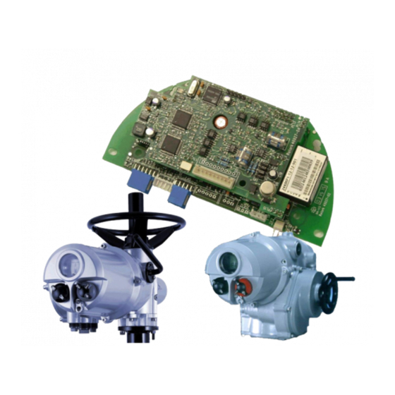
- Page 1 Profibus Actuator Control Profibus DP Option Card Installation Manual Publication PUB088-005-00_1017...
- Page 2 Note 3: The Profibus DP Module (MK2) described in this manual is suitable for inclusion in Rotork IQ, IQT, CVA, ROMPAK, Skil and Q actuators. As we are continually developing our products their design is subject to change without notice.
-
Page 3: Table Of Contents
Contents Contents Glossary of Terms: ..........................5 Abbreviations: ........................... 5 References: ............................6 INTRODUCTION ....................7 General ............................. 8 PROFIBUS DP (MK2) OPTION CARD PROPERTIES ........9 Mechanical properties ......................9 Electrical Properties ......................11 Operation and Storage ......................11 FITTING THE PROFIBUS DP (MK2) OPTION CARD ........13 Inside an IQ or IQT actuator ....................13 Inside a Q actuator ........................14 Inside a CVA actuator ......................15... - Page 4 Profibus DP Mk2 Option Card Installation Manual 5.1.6 Profibus Network Control Disable feature ............40 Digital Input Status Feedback ....................41 5.2.1 Digital Inputs .....................42 5.2.4 Digital Inputs Reporting the Profibus Card Condition ........46 Actuator Analogue Input Feedback ..................48 Configuring the Registers to be Exchanged in Cyclic Communication ......49 PROFIBUS DP COMMUNICATION ..............
-
Page 5: Glossary Of Terms
The communication protocol used on the highway. Profibus DP-V0 and DP-V1 The cyclic (V0) and acyclic (V1) versions of the protocol supported by the Rotork module. Profibus Nutzerorganisation – Profibus User Group, Germany RedCom Dual redundant system as defined in PNO 2.212... -
Page 6: References
Profibus DP Mk2 Option Card Installation Manual Process Device Manager References: Profibus Guideline 2.112 Installation Guideline for Profibus DP/FMS Profibus Guideline 2.212 Specification Slave Redundancy Profibus Guideline 2.152 Specification for Profibus Device Description and Device Integration – EDD Profibus Guideline 2.162 Specification for Profibus Device Description and Device Integration –... -
Page 7: Introduction
Introduction INTRODUCTION The Rotork Profibus DP Actuator Control option card (PFU) has been certified by the PNO as compliant with specifications IEC61158 and EN50170. The card supports both Profibus DP-V0 cyclic and Profibus DP-V1 acyclic messages. Three versions are available - single channel, simple dual channel and RedCom dual channel. -
Page 8: General
Profibus DP Mk2 Option Card Installation Manual 1.1 General The Profibus DP Module (Mk2) has three versions: Single Channel Profibus DP plus one analogue input channel Simple Dual Channel, independent isolated Profibus DP highways for redundant systems that do not support full RedCom ... -
Page 9: Profibus Dp (Mk2) Option Card Properties
Profibus Card Properties PROFIBUS DP (MK2) OPTION CARD PROPERTIES 2.1 Mechanical properties The PFU module consists of a network interface card, that either fits directly to the main actuator printed circuit board (CVA and ROMPAK) or fits to an interface card; then the two board assembly is fitted inside the actuator electrical housing (IQ range, Skil/EH and Q). - Page 10 Profibus DP Mk2 Option Card Installation Manual Interface Card (IQ/Skil/EH/Q) The CVA and ROMPAK do not require in additional interface card. The interface card is profiled and assembled to fit an IQ, Skil or Q actuator. For the Skil/EH and Q, it carries the processor for collecting the data from the actuator main board and passing this data to the Network Interface card.
-
Page 11: Electrical Properties
Profibus Card Properties 2.2 Electrical Properties The PFU connects directly to the Interface Card of the actuator. The PFU does not sit in the main control path for the actuator and does not affect the actuator control integrity. The Profibus DP fieldbus data highway connections are fully isolated from the actuator electronics. 2.3 Operation and Storage The PFU is designed to be stored in the actuator and operated within the same environment as the actuator. - Page 12 Profibus DP Mk2 Option Card Installation Manual (This page is intentionally blank) 12 of 84 Publication PUB088-005-00_1017...
-
Page 13: Fitting The Profibus Dp (Mk2) Option Card
Fitting the Profibus card FITTING THE PROFIBUS DP (MK2) OPTION CARD 3.1 Inside an IQ or IQT actuator The PFU is suitable for fitting into IQ Mk2 actuators with 3000 or 5000 series wiring diagrams and IQT with 6000 or 7000 series wiring diagrams. The connections and fitting in an IQT is similar to that for an IQ and the following information effectively relates to both actuator types. -
Page 14: Inside A Q Actuator
Profibus DP Mk2 Option Card Installation Manual 3.2 Inside a Q actuator The PFU is fitted in the option board position in this actuator. Only one option board may be fitted at any one time. The necessary internal components must also be present; in this case a potentiometer and auxiliary limit switches at end of travel must be fitted to the actuator. -
Page 15: Inside A Cva Actuator
The PFU in the CVA must be enabled. This would usually be done during factory test, but may be required to be completed on site for spares. To enable, the Rotork PDA software Enlight (downloadable from the Rotork web site) is utilised to change parameter 34. It must be read then 2048decimal added to it. -
Page 16: Inside Rompak Actuator
Profibus DP Mk2 Option Card Installation Manual 3.4 Inside ROMPAK actuator The PFU is suitable for fitting into ROMPAK actuators, wiring diagram RX0X-6X0 (where X can be any value) details the option card connections on the terminal strip. The PFU module is fitted in the only option board slot inside the ROMPAK electrical housing. -
Page 17: Inside A Skil Or Eh Actuator
Fitting the Profibus card 3.5 Inside a Skil or EH actuator The PFU is suitable for fitting into Skil and EH actuators, wiring diagram SWM SI-001 and WD18460. The PFU is normally located in the first option board slot inside the electrical housing using connection SK1. -
Page 18: Replacing Or Fitting A Profibus Dp (Mk2) Option Card
Profibus DP Mk2 Option Card Installation Manual 3.6 Replacing or Fitting a Profibus DP (Mk2) Option Card The PFU should be replaced or fitted only in a suitable environment. The actuator must be made electrically safe before opening any covers and in the case of an IQ or IQT it is advisable to disconnect the internal battery. -
Page 19: Single And Dual Data Highway Configurations
Single and Dual Data Highway Configurations SINGLE AND DUAL DATA HIGHWAY CONFIGURATIONS 4.1 Profibus Data Highway The rules governing the installation and connection of a Profibus DP highway should be observed at all times to produce a successful installation. The highway does not allow power to be transferred and the Profibus module is powered from the actuator itself. -
Page 20: Segmented Single Highway System
Profibus DP Mk2 Option Card Installation Manual 4.2 Segmented Single Highway System Bus Master Segment 1 Repeater Terminator Segment 2 Repeater Powered Active Terminator Segment 3 Fig 13: Profibus Single Channel Data Highway Topology The data highway may be connected as several segments coupled by repeaters. The repeaters or actuator slaves will require termination components if they are on the end of the segment. -
Page 21: Redundant Systems - Simple Redundancy
Single and Dual Data Highway Configurations 4.3 Redundant Systems – Simple Redundancy The Simple Dual Channel Profibus DP (Mk2) Option Card version has two redundant communications channels. Like the RedCom version, this card supports two types of redundant operation. SR –... -
Page 22: Flying Redundancy Slave To Master Connection
Profibus DP Mk2 Option Card Installation Manual 4.3.1 Flying Redundancy Slave to Master Connection Primary Master Backup Master Primary Slave 64+n Backup Fig 15: Profibus DP (Mk2) Flying Redundancy Connection With FR (Flying Redundancy) the aim is to protect against a failure of the Profibus Interface. The data highway is considered to be more reliable than the connection interface. -
Page 23: System Redundancy Slave To Master Connection
Single and Dual Data Highway Configurations 4.3.2 System Redundancy Slave to Master Connection First Master Primary Primary Slave Slave Backup Backup Second Master Fig 16: Profibus DP (Mk2) System Redundancy Connection With SR (System Redundancy) there are two data highways and the aim of the redundancy is to secure communication with the actuator even if one of the highways fails. -
Page 24: Redundant Systems - Redcom Redundancy
FR – Flying Redundancy (Two slave addresses offset by 64) The Rotork Profibus DP (Mk2) RedCom Dual Channel Option Card obeys the Profibus REDCOM Specification for Redundant Communications. This includes 3 bytes of Extended Diagnostics for RedState. Not all PLC systems can accept these diagnostic messages. -
Page 25: Extended Diagnostic Messages For Redcom
Single and Dual Data Highway Configurations 4.4.1 Extended Diagnostic Messages for RedCom The Redundancy Extensions to the standard V1 protocol allow the two channels to communicate between themselves to establish correct operation of the highway if there is a failure, both the Simple and RedCom versions of the card do this. -
Page 26: Cable Types
Profibus DP Mk2 Option Card Installation Manual 4.5 Cable Types The network must be connected using a suitable cable for Profibus DP applications. Two conductors plus a shield are required and there is a Profibus specification for the cable. Amongst the cable manufacturers Belden have the PVC jacketed single pair 2 core cable, which meets the minimum requirement. -
Page 27: Connecting To The Highway And Setting Up The Profibus Card
Single and Dual Data Highway Configurations 4.7 Connecting to the Highway and Setting up the Profibus Card The Profibus Mk2 variants allow for different highway connections. The ‘single channel’ can be used for simple highways, and where there is an analogue transmitter connected it will also return the value from the transmitter signal. - Page 28 Profibus DP Mk2 Option Card Installation Manual Data line 1B is positive with respect to data line 1A when the PFU is transmitting a ‘1’. Data line A is also called TxD/RxD-N Data line B is also called TxD/RxD-P If an analogue input is being used it is connected to the analogue input terminals.
-
Page 29: Dual Highway
Single and Dual Data Highway Configurations 4.7.2 Dual Highway The most common application of the Dual channel card is for Dual Highways in SR (System Redundancy) applications. If FR (Flying Redundancy) is being used then a similar connection at the actuator applies, but only one channel will require termination at the end of the highway. - Page 30 Profibus DP Mk2 Option Card Installation Manual connected by linking the highway ‘1A Out’ terminal to the highway 1 ‘Terminator’ terminal (blue link in diagram above) and fitting the internal links LK1 and LK2 in the Terminate position; and by linking the highway ‘2A Out’...
-
Page 31: Optional Iq And Iqt Disconnect Module
Single and Dual Data Highway Configurations 4.7.2 Optional IQ and IQT disconnect module The IQ and IQT range of actuators can be fitted with an optional disconnect module, the purpose of which is to enable the removal of the actuator for service without disrupting the network. Without the disconnect module, due to the ‘IN’... - Page 32 ROTORK designed parking housing (refer to ROTORK for more information). 32 of 84 Publication PUB088-005-00_1017...
-
Page 33: The Actuator Cyclic Data Signals
Input and Output Signals THE ACTUATOR CYCLIC DATA SIGNALS The Profibus DP Module (Mk2) allows the actuator to be controlled by, and to report data to, a suitable host device using Profibus DP protocol. This section explains the data signals that are presented during cyclic V0 data exchange and their meaning in relation to the actuator functionality. -
Page 34: Control Outputs
Profibus DP Mk2 Option Card Installation Manual 5.1 Control Outputs The Profibus DP Module (Mk2) can be used to control the actuator and position the valve. The valve may be moved fully closed, fully open or to an intermediate position. Additionally, the actuator can make the valve adopt an Emergency Shut Down position. - Page 35 Input and Output Signals Note: – Requires Extra Relay Indication board to be fitted – Push to Run action only. Maintained action not available if analogue positioning is used – Network Disable not available on Q or ROMPAK ranges ...
- Page 36 Profibus DP Mk2 Option Card Installation Manual but whilst the Profibus outputs are being written the positioner is continuously being updated. A new value in the Position DV register will cause a new position to be adopted and a new bit set in the ACTCON register will cancel positioning mode.
-
Page 37: Controls Priority
Input and Output Signals 5.1.1 Controls Priority Since there are three potential sources for control inputs the actuator and Profibus DP Module (Mk2) assign a priority for those occasions when two or more commands are applied simultaneously. IQ / IQT, Skil/EH controls priority Local controls go direct to the main board and override any Profibus controls and any hard-wired controls except hard-wired ESD. - Page 38 Profibus DP Mk2 Option Card Installation Manual Q controls priority In the case of the Q actuator the control selection is slightly different because the actuator uses a different control circuit. The Local Controls have a higher priority than hard-wired or Profibus controls and the hard-wired and Profibus controls share the same priority level ...
-
Page 39: Profibus Control Using The Actcon Register
Input and Output Signals 5.1.2 Profibus Control using the ACTCON Register A single register is provided to allow the digital control of the actuator. Writing to the individual bits in the register causes the actuator to open, close, stop, ESD, adopt Positioning mode or perform a Partial Stroke and at the same time cancels any other command set. -
Page 40: The Iq 'S' Contacts (Profibus Dos) Controlled By The O_Stat Register
Profibus DP Mk2 Option Card Installation Manual The IQ ‘S’ contacts (Profibus DOs) controlled by the O_STAT register 5.1.4 The IQ/IQT actuator has four ‘S’ contact outputs that may be configured to report the status of the actuator with signals such as Open Limit, Closed Limit etc. These are identified as S1 to S4. In addition, an optional extra relay indication board can be fitted with four more relays. -
Page 41: Digital Input Status Feedback
Input and Output Signals 5.2 Digital Input Status Feedback The Profibus DP Module (Mk2) cyclically reports over the network a comprehensive data set relating to the status of the valve, actuator and card settings as indicated in the table below. Register Name Status Feedback Skil... -
Page 42: Digital Inputs
Profibus DP Mk2 Option Card Installation Manual 5.2.1 Digital Inputs Actuator Moving Whenever the actuator position is changing due to the motor running or in the case of the IQ or IQT if the output drive is moving, this bit will be set true (1). - Page 43 Input and Output Signals if the motor is de-energised. Engaging the manual override breaks the thermostat switch which prevents motor operation. Monitor Relay This signal is true (1) when actuator remote control is not available. The actuator Monitor Relay status is a composite signal for several alarms.
- Page 44 Profibus DP Mk2 Option Card Installation Manual Moving Inhibited This bit will be true (1) when the Motion Inhibit Timer is active or the Interrupter Timer is active (IQ/IQT only), or both are active. The Motion Inhibit Timer is used in position control to prevent the actuator from exceeding its prescribed number of starts per hour, or to reduce the effects of hunting during closed loop control.
- Page 45 Input and Output Signals Digital Input DI-1 Applicable to IQ/IQT/Skil/EH actuators only. This bit reports the status of the contact connected to the actuator hard-wired Open terminals. The input can be used to control the actuator or simply to report the status of a plant feedback signal.
-
Page 46: Digital Inputs Reporting The Profibus Card Condition
Profibus DP Mk2 Option Card Installation Manual 5.2.4 Digital Inputs Reporting the Profibus Card Condition GSD Parameterisation Permitted If the actuator and card is being parameterised using either the FDT, PDM programmes and the associated device description files, or (for the IQ/IQT only) using the Infra-red tool, then the ability to alter the card parameters by the GSD may need to be removed. - Page 47 Input and Output Signals Backup or Primary Channel This bit is used to indicate if the Profibus communication is to a channel on the card that is able to move the valve (Primary) or to a channel that is prevented from operating the valve (Backup). When the communication is to the Primary Profibus DP channel the bit will be off (0).
-
Page 48: Actuator Analogue Input Feedback
Profibus DP Mk2 Option Card Installation Manual 5.3 Actuator Analogue Input Feedback The Profibus DP Module (Mk2) makes available over the network a number of analogue variables. These contain information about the valve and actuator. If the single highway with analogue input variant of the Profibus DP Module (Mk2) is used, one associated plant measurement is also available. -
Page 49: Configuring The Registers To Be Exchanged In Cyclic Communication
Input and Output Signals Analogue Input The current value of the analogue input is reported as an Integer Value in the range 0 to 1000 (0 – 3E8 hex) representing the percentage value to 0.1% resolution. The input may be 0 to 5V or 0 to 20mA d.c. from an externally powered field transmitter (the actuator does not provide the power for the transmitter). - Page 50 Profibus DP Mk2 Option Card Installation Manual (This page is intentionally blank) 50 of 84 Publication PUB088-005-00_1017...
-
Page 51: Profibus Dp Communication
Profibus Communication PROFIBUS DP COMMUNICATION 6.1 Electrical Specification Line Electrical Specification: RS485, two wire, half duplex 6.2 Protocol Profibus DP Cyclic (V0) and Acyclic (V1) communication Supported Baud Rates 9k6, 19k2, 45k45, 93k75, 187k5, 500k, 1M5 Data Speed (Baud) 19k2 45k45 93k75 187k5... -
Page 52: Dual Highway, Dual Channel - Sr Mode
Profibus DP Mk2 Option Card Installation Manual LED 3 LED 4 LED 2 EPROM LED 1 SK10 Fig 32: Single Channel Profibus card LED positions Description State Function On (Red) In data exchange mode with PLC Channel 1 Data Exchange Not in data exchange mode On (Red) Ready to reply to PLC... - Page 53 Profibus Communication directly with the actuator and the IQ setting tool. For all actuator variants the address can be set over the highway using a Class 2 master. Baud Rate This is selected by the PLC, both channels adopt the same baud rate. ...
-
Page 54: Single Highway Dual Channel - Fr Mode
Profibus DP Mk2 Option Card Installation Manual 6.5 Single Highway Dual Channel – FR Mode On either the Simple or RedCom dual channel card the mode for communications may be set to FR (Flying Redundancy) in some cases. This will require the card’s GSD file to be changed or the parameter value altered by a PDM or FDT utility. -
Page 55: Dual Channel Indication Leds
Profibus Communication Note: FR Mode - Primary is offset from Backup address by 64. When the card is powered ‘on’ Channel 1 will be the Primary channel. After power up the card will seek a master to communicate with by alternating the channel 1 and 2 between Primary and Secondary mode. -
Page 56: Basic Operation On Start Up
Profibus DP Mk2 Option Card Installation Manual Description State Function Flash (Green) PLC comms not present Solid (Green) Data being exchanged with PLC Diagnostic Solid (Red) Fatal Error Flash (Red) After solid green shows comms lost On (Red) In data exchange mode with PLC Channel 2 Data Exchange Not in data exchange mode On (Red) -
Page 57: Static Diagnostics
Profibus Communication 6.8 Static Diagnostics Within the standard Profibus Diagnostics reply is a bit named ‘Static Diagnostic’. In the unlikely event that the PFU loses communication with the main board to which it is connected, this bit will be asserted to alert the user to this situation. If the PFU is unable to communicate to the main board, the data which is sent in data exchange communication is potentially stale (not current). - Page 58 Profibus DP Mk2 Option Card Installation Manual (This page is intentionally blank) 58 of 84 Publication PUB088-005-00_1017...
-
Page 59: Parameters
Parameters PARAMETERS 7.1 Parameters set by GSD and DP-V1 Communication Profibus defines a power on reset sequence for all devices as: Diagnostic Request Set Parameterisation Check Configuration / Set Configuration Diagnostic Request Data Exchange After a successful Diagnostic Request the Set Parameterisation Telegram is sent from the PLC. The Set Parameter message contains the user defined Parameter Data Unit (DU) of a minimum of 7 bytes, max 244 bytes. - Page 60 Profibus DP Mk2 Option Card Installation Manual Param. Description Value/Range Default Value 0 – 255 sec Watchdog Timeout 10 sec 0000 – 00FF hex 000A hex Action on Loss of Comms 0 = Nothing (No Action) 0 = Nothing 1 = Open (0000 hex) 3 = Close 5 = Stop...
-
Page 61: Limited Range Position Minimum And Maximum (Parameter 1 And 2)
Parameters 7.1.1 Limited Range Position Minimum and Maximum (Parameter 1 and 2) These parameter registers are used to define the positions in the range of valve travel that will be reported as 0 to 100% if it the whole travel from the closed position to the open position is not used. In addition the position demand setpoint output value will also be modified to follow this limited range. -
Page 62: Slow Mode Range (Parameter 5)
Profibus DP Mk2 Option Card Installation Manual is within 5% of the desired position. The inertia will then bring the actual position nearer the desired position. The deadband is the allowable error around the setpoint. Hysteresis In addition to the deadband a second setting, hysteresis, further refines the performance of the position controller. -
Page 63: Manual Movement Travel (Parameter 7)
Parameters In addition, when tuning the valve positioner the setting can be used to allow the plant dynamics to stabilise between valve movements. Not supported by CVA. 7.1.5 Manual Movement Travel (Parameter 7) Manual Movement Travel sets the amount of valve travel not under motor action that is permitted before being considered 'Manual Movement'. -
Page 64: Comms Fault Timer (Parameter 12)
Profibus DP Mk2 Option Card Installation Manual 7.1.10 Comms Fault Timer (Parameter 12) Parameter 12, the Comms Fault Timer setting, determines the number of seconds that network communication must be absent before the setting for the Fault Mode will be carried out. 7.1.11 Auxiliary Input Mask (Parameter 13) This parameter relates to IQ/IQT/Skil/EH actuators only and allows the auxiliary inputs (open, stop,... -
Page 65: Esd Di-4/Net Disable And Data Logger Disable (Parameter 14)
Parameters The following examples show how the Auxiliary Input Mask settings can be applied. Most Significant Bit Least Significant Bit Bit 7 Bit 6 Bit 5 Bit 4 Bit 3 Bit 2 Bit 1 Bit 0 Enable Enable Enable Enable Invert Invert Invert... -
Page 66: Redundancy Fr/Sr Mode And Simple/Redcom Mode (Parameter 15)
Profibus DP Mk2 Option Card Installation Manual 7.1.13 Redundancy FR/SR Mode and Simple/RedCom Mode (Parameter 15) When using either type of dual channel card there are two methods for redundancy that can be used, Flying Redundancy, where the two channels have addresses 64 apart, and System Redundancy, where they have the same address. -
Page 67: Parameters Viewed And Set By Dp-V1 Communication
Parameters 7.2 Parameters viewed and set by DP-V1 Communication The Profibus DP Module (Mk2) supports V1 acyclic communication as well as V0 cyclic messages. These parameters can be accessed in a number of ways including using standard Profibus tools and the specialist device description files associated with them. - Page 68 These are ‘Actuator Parameters’ and are for the IQ and IQT range ONLY. 70-77 If Torque Profiling is selected, these 16 bytes parameters contain the variables used for this. Rotork use only. Function for Indication contact S1 Bit 0: 0-Normally 0000 Open, 1 – Normally...
- Page 69 Parameters Parameter Read / Data Value / Range Default Value Write ‘PO’ contact S4 Function for Indication contact S5 Bit 0: 0-Normally 0001 Open, 1 – normally Function for Indication contact S6 0003 closed. Function for Indication contact S7 000D Bits 1 to 15: Function for Indication contact S8 002B...
-
Page 70: Actuator Tag Data (Parameter 20)
Profibus DP Mk2 Option Card Installation Manual Parameter Read / Data Value / Range Default Value Write ID Option1 16bytes ASCII ID Option 2 16bytes ASCII ID Option 3 16bytes ASCII ID Option 4 16bytes ASCII Manufacture notes 48bytes ASCII General Notes 67bytes ASCII ... -
Page 71: Actuator Feedback Data (Parameter 30 To 36)
Parameters 7.2.7 Actuator Feedback Data (parameter 30 to 36) These 7 parameters replicate the data reported in the cyclic registers described in section 5.2 and 5.3 and also allow for the calibration of the Analogue Input. Parameter Register Description IDATA1 and IDATA2 Actuator status IDATA3 and IDATA4 Actuator status... -
Page 72: Data Logger Information (Parameter 42 To 67)
Profibus DP Mk2 Option Card Installation Manual 7.2.10 Data Logger Information (Parameter 42 to 67) The Profibus card makes available some of the IQ and IQT data logged information from parameters in the data base. The data available is updated shortly after the actuator stops moving provided the actuator selector is in the ‘Remote’... -
Page 73: Function For Indication Contacts S1 - S8 (Parameters 78-81 And 86-89)
Parameters Function for indication Contacts S1 – S8 (Parameters 78-81 and 86-89) 7.2.12 These parameters enable the indication contacts S1 to S8 to be set to trip to any one of the following functions. The contact can be set to Normally Open or Normally Closed using bit 0. Value, Description Bits 1-... -
Page 74: Esd Parameters (Parameter 97 - 101)
Profibus DP Mk2 Option Card Installation Manual 7.2.14 ESD Parameters (Parameter 97 - 101) The ESD signal is used to operate actuators to a pre-determined state, under shutdown conditions. There are a number of settings that can be made for this operation. ... -
Page 75: Language Used (Parameter 109)
Parameters Interrupter Timer activated when opening if below xx% (Parameter 107) This parameter sets the position that the interrupter timer start to be active when the actuator is travelling in the open direction. Interrupter Timer activated when closing if above xx% (Parameter 108) This parameter sets the position that the interrupter timer start to be active when the actuator is travelling in the close direction. - Page 76 Profibus DP Mk2 Option Card Installation Manual (This page is intentionally blank) 76 of 84 Publication PUB088-005-00_1017...
-
Page 77: Setting Up And Maintaining The Profibus Module
This utility uses DTM device description files and a suitable FDT container. A typical configuration screen is illustrated below. Fig 39: Rotork DTM running in the M&M FDT container The settings for the parameters and the control and review of actuator information can all be carried out in the FDT container using the DTM. -
Page 78: Pdm (Process Device Manager)
This utility uses EDD device description files and the PDM programme from Siemens. A typical configuration screen is illustrated below. Fig 40: Rotork EDD running in the Siemens PDM application As with FDT, the parameters and the control and review of actuator information can all be carried out in PDM using the EDD device description file. -
Page 79: Setting Up The Network Address In The Pfu
Setting Up a Card 8.2 Setting up the network address in the PFU The IQ and IQT actuator includes an infra-red communication port for setting the network address for the actuator. The other actuators require the address to be set up over the Profibus network using a class 2 master. - Page 80 Profibus DP Mk2 Option Card Installation Manual Note that changes to the address by the IR link require a power cycle of the actuator before the new address becomes effective. If the address is changed using a Class 2 master directly on the Profibus link then the new address becomes effective immediately.
-
Page 81: Setting Up A Skil Or Eh With The Infra-Red Setting Tool
Setting Up a Card 8.3 Setting up a Skil or EH with the Infra-red Setting Tool The Skil and EH actuator includes an infra-red communication port for setting the actuator performance, limit switches and so on. This communication link is also used to select the remote source for the actuator. -
Page 82: Records
Profibus DP Mk2 Option Card Installation Manual 8.4 Records In order that a replacement can be easily introduced in the event of a device failure it is very important to record and keep safe all the settings made for the variable registers. The table lists all the registers that must be checked and set up for each Profibus Module on a network. - Page 83 Setting Up a Card (This page is intentionally blank) Publication PUB088-005-00_1017 83 of 84...
- Page 84 Document Formerly S420 UK Head Office Rotork plc http://www.rotork.com Brassmill Lane, Bath, UK Rotork reserves the right to amend and change Tel: +44 (0) 1225 733 200 specifications without prior Fax: +44 (0) 1225 333 467 notice. e-mail: mail@rotork.com Published data may be...
Need help?
Do you have a question about the Profibus Modbus Module Mk2 and is the answer not in the manual?
Questions and answers