Sign In
Upload
Manuals
Brands
rotork Manuals
Controller
Profibus Modbus Module Mk2
rotork Profibus Modbus Module Mk2 Manuals
Manuals and User Guides for rotork Profibus Modbus Module Mk2. We have
1
rotork Profibus Modbus Module Mk2 manual available for free PDF download: Installation Manual
rotork Profibus Modbus Module Mk2 Installation Manual (84 pages)
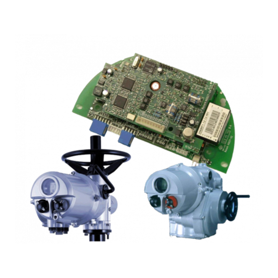
Profibus Actuator Control Profibus DP Option Card
Brand:
rotork
| Category:
Controller
| Size: 2.11 MB
Table of Contents
Table of Contents
3
Glossary of Terms
5
Abbreviations
5
References
6
1 Introduction
7
General
8
2 Profibus Dp (Mk2) Option Card Properties
9
Mechanical Properties
9
Electrical Properties
11
Operation and Storage
11
3 Fitting the Profibus Dp (Mk2) Option Card
13
Inside an IQ or IQT Actuator
13
Inside a Q Actuator
14
Inside a CVA Actuator
15
Inside ROMPAK Actuator
16
Inside a Skil or EH Actuator
17
Replacing or Fitting a Profibus DP (Mk2) Option Card
18
4 Single and Dual Data Highway Configurations
19
Profibus Data Highway
19
Segmented Single Highway System
20
Redundant Systems - Simple Redundancy
21
Flying Redundancy Slave to Master Connection
22
System Redundancy Slave to Master Connection
23
Redundant Systems - Redcom Redundancy
24
Extended Diagnostic Messages for Redcom
25
Cable Types
26
Termination Network
26
Connecting to the Highway and Setting up the Profibus Card
27
Single Highway with Analogue Input
27
Dual Highway
29
Optional IQ and IQT Disconnect Module
31
5 The Actuator Cyclic Data Signals
33
Control Outputs
34
Controls Priority
37
Profibus Control Using the ACTCON Register
39
Profibus Control Using the POS_DV Register
39
The IQ 'S' Contacts (Profibus Dos) Controlled by the O_STAT Register
40
Multiport Position Selection Using the PORTCM Register (Future)
40
Profibus Network Control Disable Feature
40
Digital Input Status Feedback
41
Digital Inputs
42
Digital Inputs Reporting the Profibus Card Condition
46
Actuator Analogue Input Feedback
48
Configuring the Registers to be Exchanged in Cyclic Communication
49
6 Profibus Dp Communication
51
Electrical Specification
51
Protocol
51
Single Highway, Single Channel
51
Dual Highway, Dual Channel - SR Mode
52
Single Highway Dual Channel - FR Mode
54
Dual Channel Indication Leds
55
Basic Operation on Start up
56
Static Diagnostics
57
7 Parameters
59
Parameters Set by GSD and DP-V1 Communication
59
Limited Range Position Minimum and Maximum (Parameter 1 and 2)
61
Deadband and Hysteresis (Parameter 3 and 4)
61
Slow Mode Range (Parameter 5)
62
Motion Inhibit Timer (Parameter 6)
62
Manual Movement Travel (Parameter 7)
63
Valve Jammed Time (Parameter 8)
63
Watchdog Timeout (Parameter 9)
63
Action on Loss of Comms (Parameter 10)
63
Comms Lost Position (Parameter 11)
63
Comms Fault Timer (Parameter 12)
64
Auxiliary Input Mask (Parameter 13)
64
ESD DI-4/Net Disable and Data Logger Disable (Parameter 14)
65
Redundancy FR/SR Mode and Simple/Redcom Mode (Parameter 15)
66
Part Stroke Position (Parameter 16)
66
Part Stroke Limit and Timeout (Parameter 17)
66
Actuator Type (Parameter 18)
66
Parameters Viewed and Set by DP-V1 Communication
67
Actuator Tag Data (Parameter 20)
70
Software Versions (Parameter 21 and 22)
70
Field Interface Type (Parameter 24)
70
Permit GSD Parameterisation (Parameter 25)
70
Control Outputs (Parameter 26 to 29)
70
Actuator Feedback Data (Parameter 30 to 36)
71
Multiport Feedback and Setup (Parameter 37 to 39)
71
Configure Data Exchange (Parameter 40)
71
Data Logger Information (Parameter 42 to 67)
72
Parameterisation Date (Parameter 68)
72
Function for Indication Contacts S1 - S8 (Parameters 78-81 and 86-89)
73
Position Trip for Indication Contacts S1 - S8 (Parameters 82-85 and 90-93)
73
ESD Parameters (Parameter 97 - 101)
74
Interlock Enable (Parameter 102)
74
Open Limit Position (Parameter 103)
74
Interrupter Timer Parameters (104 - 108)
74
Language Used (Parameter 109)
75
Ids and Notes (Parameters 111 - 120)
75
8 Setting up and Maintaining the Profibus Module
77
Using a Network Configuration Tool
77
FDT (Field Device Tool)
77
PDM (Process Device Manager)
78
Setting up the Network Address in the PFU
79
Setting up an IQ or IQT with the Infra-Red Setting Tool
79
Setting up a Skil or EH with the Infra-Red Setting Tool
81
Maintenance and Repair
81
Records
82
Advertisement
Advertisement
Related Products
rotork Modbus IQ Pro
rotork Modbus Q
rotork Modbus IQT Pro
rotork Modbus SI Pro
rotork Modbus EH Pro
rotork Modbus ROMpak
rotork Master Station
rotork MV-1000 Series
rotork MV-1010
rotork MV-1020
rotork Categories
Controller
Valve Positioners
Industrial Equipment
Control Unit
Control Systems
More rotork Manuals
Login
Sign In
OR
Sign in with Facebook
Sign in with Google
Upload manual
Upload from disk
Upload from URL