
Subscribe to Our Youtube Channel
Related Manuals for rotork CK Atronik Series


Summary of Contents for rotork CK Atronik Series
- Page 1 Range & CK – Atronik Start Up Guide Modular Design Electric Valve Actuators...
-
Page 2: Table Of Contents
Rotork provides an efficient sales service, after Rotork has an extensive product range catering for all sales commissioning and maintenance support throughout industries. Our actuation solutions deliver state-of-the-art the life of the actuator. -
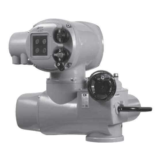
Page 3: Actuator Identification
The Atronik name plate will enable you to identify your unit. Model Example below: Serial Number Power Supply Customer Supply Backup Supply P max Supplied and Tested by Rotork Model : ATRONIK Wiring Diagram Serial nº : S0000000102 Internal Diagram Power supply : 3~380V/50Hz Cust. -
Page 4: Commissioning
Commissioning Mechanical Switch Mechanism Test Feedback Switches 1) Confirm the torque or limit switches are functional by monitoring feedback on the Atronik status indicators during switch testing. The main power supply must be maintained during this test procedure to ensure feedback via the Atronik. - Page 5 Commissioning A 5 mm Allen (Hex.) key and 0.8 x 4 mm flat screwdriver are required to perform commissioning of the CK Mechanical Switch Mechanism. Set torque limits A Indicator/Adjustment Point Torque Cam Clutch Screw 1) Move the valve to a mid-travel position and loosen the Torque Cam Clutch 1.5 turns using a flat screwdriver.
- Page 6 Commissioning Set Position Limits OLS Indicator Window G OLS Adjustment Screw H Drive Clutch Shaft CLS Indicator Window CLS Adjustment Screw 1) Move actuator to the valve CLOSED position using handwheel operation. 2) Using a flat screwdriver, depress the Drive Clutch Shaft and rotate to “SET”...
- Page 7 Commissioning 8) Move actuator to the valve OPEN position using handwheel operation. 9) Using a flat screwdriver, depress the Drive Clutch Shaft and rotate to “SET” position as shown on the switch mechanism faceplate. 10) The OLS Adjustment Screw must now be rotated to make the open limit switch inside the switch mechanism.
-
Page 8: Additional Indication Drive
Commissioning Additional Indication Drive The Additional Indication Drive (AID) supplements the mechanical switch mechanism to increase functionality. Test Feedback Switches 1) Confirm the torque or limit switches are functional by monitoring feedback on the Atronik status indicators during switch testing. The main power supply must be maintained during this test procedure to ensure feedback via the Atronik. - Page 9 Open and Close limit positions. A series of reduction gears ensure a suitable range of travel can be accommodated. If more turns are required please contact Rotork. CAUTION: The actuator position limits must be configured prior to setting the Local Position Disc.
- Page 10 Commissioning 6) Move the actuator to the OPEN limit using electrical or operation or the handwheel. 7) Loosen off the Position Disc Retaining Screw by 1 turn whilst holding the CLOSE portion of the Position Disc. 8) Rotate only the red OPEN portion of the disc so that OPEN reads horizontally and then hold both portions in place.
- Page 11 Commissioning Setting Intermediate Switches The AID Module can include four additional switches to indicate configurable intermediate positions. CAUTION: The actuator position limits must be configured prior to setting the Intermediate Switches. 1) Move the actuator to the desired intermediate position using electrical operation or the handwheel.
- Page 12 POT to be scaled according to the total valve travel. For information on which ratio is suitable for your application please contact Rotork. If the POT is connected to the Atronik, fine adjustment of the POT travel is not required.
- Page 13 Commissioning Setting the CPT Once the POT drive is commissioned for full valve travel, the CPT can be calibrated to output a 4-20 mA loop powered signal. This can be used as direct actuator position feedback to the site control system. The CPT option includes two different trimming potentiometers to enable zero and span values to be calibrated.
-
Page 14: Ck Atronik
CK Atronik Standard Settings Configuration of the Atronik control module is performed via DIP switches located on the user interface PCB within the Atronik enclosure. DIP switch functions Label Function ESD FUNCTION A A OFF and B OFF = Disabled A ON and B ON = Stay put ESD Action A ON and B OFF = Open A OFF and B ON = Close... -
Page 15: Option Settings
CK Atronik Option Settings Extra Relays Atronik can accommodate four additional relay contacts with configurable functions. These are determined by DIP switches located on the extra relay PCB. Switch 1 Switch 2 Switch 3 Relay 3 Function Relay 4 Function Open Limit Closed Limit Torque Trip Open... - Page 16 As part of a process of on-going product development, Rotork reserves the right to amend and change specifications without prior notice. Published data may be subject to change. For the very latest version release, visit our website at www.rotork.com PUB111-110-00 The name Rotork is a registered trademark.
Need help?
Do you have a question about the CK Atronik Series and is the answer not in the manual?
Questions and answers