Table of Contents
Advertisement
Advertisement
Table of Contents

Related Manuals for rotork IQ70 F25 B4


Summary of Contents for rotork IQ70 F25 B4
- Page 1 IQ Range Instructions for Safe Use, Installation, Basic Setup and Maintenance This manual contains important safety information. Please ensure it is thoroughly read and understood before installing, operating or maintaining the equipment. PUB002-039-00 Date of issue 02/19...
-
Page 2: Table Of Contents
6.1 Rising Stem Valves Top Mounted ... . 15 1.2 Rotork Setting Tool ..... . . 4 6.2 Valve with Gearbox –... -
Page 3: Introduction
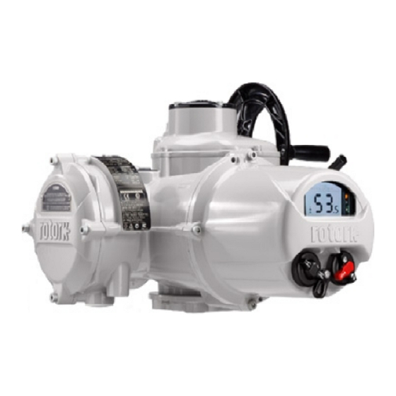
Introduction 1.1 Identifying Actuator Parts Battery sealing plug Metal (8 mm Allen key required) Side hand wheel Plastic (10 mm Allen key required) as appropriate. Hand / Auto lever Hand wheel Name plate Display window Oil plug Control Cover Oil plug Terminal Cover Conduit entries Local / Remote / Stop... -
Page 4: Rotork Setting Tool
2. The following checks must be conducted applicable code of practice. The new BTST is able to connect to Rotork USA – FM Int Safe Class I, Div 1, Groups A, on the BTST prior to taking it into a Bluetooth ®... -
Page 5: Introduction To This Manual
It should only be installed in hazardous of the Rotork IQ range of actuators be area locations compatible with the Visit our web site at www.rotork.com required, it will be provided on request. - Page 6 WARNING: Operating by Hand If the actuator is configured to With respect to handwheel operation bypass the motor thermostat then of Rotork electric actuators, refer to the hazardous area certification will section 4.1. be invalidated. Additional electrical hazards may occur when using this configuration.
-
Page 7: Atex/Iec Ex Certified Actuators
Rotork. covers are removed. Every Rotork actuator has been fully tested before leaving the factory to give years of trouble free operation, providing it is correctly commissioned, installed and sealed. -
Page 8: Operating Your Iq Actuator
It is not necessary to check phase With respect to handwheel original position. The handwheel will rotation. operation of Rotork electric remain engaged until the actuator Do not operate the actuator actuators, under no circumstances is operated electrically when it will... -
Page 9: Display - Local Indication
4.3 Display - Local Indication Infra-red LEDs Percentage Open Icon This icon will be displayed when an Used for older models of setting tool integer open value is displayed e.g. and to initiate a data connection using 57.3. Bluetooth wireless technology. 10. -
Page 10: Display - Home Screen Selection
4.4 Display – Home screen selection Permanent Home Screen display. Once selected, the set display will be the active, permanent home screen. Using the setting tool (refer to 8.1) The actuator display can be set to show Refer to Figs 4.4.2 to 4.4.5. connect to the actuator. -
Page 11: Display Status Indication - Travel
4.5 Display Status Indication – 4.6 Display Status Indication – 4.7 Display Alarm Indication 4.8 Battery Alarm Travel Control The IQ display provides alarm indication The IQ display provides real-time status The bottom line of the text area is in the form of text and alarm icons. indication. -
Page 12: Preparing The Drive Bush
Preparing the Drive Bush Disassembly of bearing assembly all sizes 5.1 IQ base all sizes types A and Z3 Locate and remove the snap ring (5) Thrust Base Thrust Base using a suitable tool. Remove the Housing Turn actuator onto its side, remove the Housing split collar (4) See Fig. -
Page 13: Non-Thrust Base Type B
Reassembly 5.2 Non-Thrust Base Type B Types B3 and B4 Removal WARNING: Failure to fully clean Using external circlip pliers, expand the All Sizes and grease the drive bush and circlip while pulling on the drive bush. Thrust Base Undo the hex head bolts securing the O-rings before reassembly could The drive bush will detach from the Housing... -
Page 14: Mounting The Actuator
Mounting the Actuator WARNING: IQ Cover Tubes. Cover tubes not supplied by Rotork Refer to Section 11 Weights and shall be designed to ensure that Measures for actuator weight. they do not exceed BOTH mass and moment parameters listed in Ensure the valve is secure before fitting Section 11 Weights and Measures. -
Page 15: Rising Stem Valves Top Mounted
6.1 Rising Stem Valves Top Mounted Continue to turn actuator until fixing 6.2 Valve with Gearbox – Side Metric Torque Mounting holes align. Using bolts supplied fix Fitting the Actuator and Base as a Flange Fixing lbs.ft actuator to thrust base and tighten combined unit, all sizes. -
Page 16: Handwheel Sealing
6.4 Handwheel Sealing 6.5 IQM Modulating Actuators 6.6 IQL & IQML Linear Drive Unit Ensure that the sealing cap and The IQM range of actuators are Consists of a lead screw assembly O-ring is fitted securely to ensure that suitable for modulating control duty of arrangement attached to the base moisture does not pass down the up to 1,200 starts per hour. -
Page 17: Iql & Iqml Adjusting Linear Stroke
6.7 IQL & IQML Adjusting Linear couple the linear drive to valve spindle. Cable Connections Stroke Turn the tubular down stop clockwise into the actuator until it comes to a Terminal Block Layout With the actuator securely fitted to mechanical stop. If the valve must close the valve, but with the linear drive into its seat by TORQUE ACTION then disconnected ensure valve is at its fully... -
Page 18: Earth/Ground Connections
The switch or circuit separately in shipping box). or cables contained within conduit. breaker must not disconnect the The Rotork Bluetooth setting tool is protective earth conductor. The switch 7.2 Earth/Ground Connections A plastic bag in the terminal packed separately, with the actuator,... - Page 19 ATTENTION: RED PLASTIC PLUGS IN CONDUIT ENTRIES ARE FOR TRANSIT ONLY. FOR LONG TERM PROTECTION FIT SUITABLE METAL PLUGS. ATTENZIONE: I TAPPI IN PLASTICA ROSSA PER L'ENTRATA CAVI SONO SOLO TEMPORANEI. PER UNA PROTEZIONE PERMANENTE PREGO SOSTITUIRLI CON APPOSITI TAPPI METALLICI. ATENCION: LOS TAPONES ROJOS DE PLASTICO EN LAS ENTRADAS DE CABLE SON UNICAMENTE PARA TRANSPORTE.
-
Page 20: Cable Entry
7.4 Cable Entry Remove plastic transit plugs. Make cable entries appropriate to the cable Only appropriate certified explosion type and size. proof cable glands or conduit may be Ensure that threaded adaptors, cable used in hazardous locations. The cable glands or conduit are tight and fully entries in the actuator are tapped M25 waterproof. -
Page 21: Replacing Terminal Cover
Failure to do so may result in asset management data is accessed INSTRUCTION ON MAKING THE connections working loose or Remove power terminal guard. using the supplied Rotork Bluetooth ® BASIC SETTINGS ONLY. screws not clamping down on Setting Tool Pro. Status and alarm data Begin by connecting power cables and wire termination tags. -
Page 22: Connecting To The Actuator
The Setting Tool will automatically using Bluetooth connect using Bluetooth which Pro with the relevant navigation and The Rotork Setting Tool incorporating configuration keys is shown below. takes up to 5 seconds and when The default security set in the actuator... -
Page 23: Security - Password
Press the key to select. If the user does not wish to change If the actuator is selected to Remote ROTORK is displayed and the OK the function value, press the and a setting is selected, the following key is highlighted. -
Page 24: Basic Settings Menu
The highlight will return to the function 8.3 Basic Settings Menu Use the arrow keys to change name only and its stored setting will be the setting to the required value, the displayed: example below show a close action of Torque having been selected. -
Page 25: Basic Settings - Limits
8.4 Basic Settings – Limits The settings menu will be displayed: The limit settings are shown below with their factory default values: Settings and operation must be Settings Limits verified by electric operation and Limits Close Settings function test of the actuated valve. Indication 1 / 15 Direction... -
Page 26: Close Settings
8.5 Close Settings 2 / 15. Close Action 3 / 15. Close Torque 8.6 Open Settings The actuator can be configured close The value of torque available to close 1 / 15. Close Direction 5 / 15. Open Action on torque for seating valve types or the valve can be set between 40% Function sets the direction required to The actuator can be configured open... -
Page 27: Torque Switch Bypass
7 / 15. Set Open Limit 8.7 Torque Switch Bypass 12 / 15. Opening Bypass position 14 / 15. Closing Bypass position Press to select Open Limit Function. When enabled (refer to 11 / 15), the When enabled (refer to 13 / 15), the The default setting for opening and The actuator will display the following position over the opening stroke where... -
Page 28: Maintenance, Monitoring And Troubleshooting
Maintenance hazardous area permission must be changes are tracked by the absolute • Check actuator to valve fixing bolts Every Rotork actuator has been fully obtained in the form of a "hot work encoder. for tightness. tested before dispatch to give years of permit"... - Page 29 (when opening) For watertight (WT) actuator Example shows that actuator at 35.0% and closing (when closing) torque enclosures Rotork recommend a lithium open, producing 27% of rated torque. Torque and Position Monitoring manganese dioxide battery, however The warning triangle indicates the switches (refer to 8.5 and 8.6).
-
Page 30: Environmental
10. Environmental End user advice on disposal at end of life of the product. In all cases check local authority regulation before disposal. EU Waste Subject Definition Remarks / examples Hazardous Recyclable Disposal Code Will require special treatment before Lithium IQ battery 16 06 06 Batteries... -
Page 31: Weights And Measures
O-rings use either Multis EP2 / If inverted installation (base uppermost) Lubricating oil Lithoshield EP2 or equivalent for all was specified with the order, Rotork temperature ranges between will oil fill to the quantities shown Refer to actuator name plate. IQ -50 and +70 ºC (-58 and +158 ºF). -
Page 32: Iq Approvals
IQ Cover tubes 12. IQ Approvals European – Hazardous Area Cover tubes not supplied by Rotork ATEX (2014/34/EU) II 2 GD c Refer to actuator nameplate for unit shall be designed to ensure that they Ex d IIB T4 Gb specific approval details. - Page 33 *Option -40°C to +70°C (-40°F to +158°F) *Option -40°C to +70°C (-40°F to +158°F) *Option -50°C to +40°C (-58°F to +104°F). Rotork can supply actuators to national *Option -50°C to +40°C (- 58°F to +104°F) standards not listed above. For details Class I, Division 1, Groups B, C &...
-
Page 34: Approved Fuses
13. Approved Fuses 14. Vibration, Shock and Noise 15. Conditions of Safe Use FS1 = Bussman TDC11 (rating as per Standard IQ range actuators are 15.1 Thread details for ATEX and IECEx Approved actuators transformer type. See actuator wiring suitable for applications where diagram for transformer type). -
Page 35: Maximum Constructional Flamepath Gaps For Atex And Iecex Approved Actuators
15.2 Maximum constructional flamepath gaps for ATEX and IECEx Approved actuators. Flamepath Max. Gap (mm) Min. Length (mm) Actuator Type and Size Motor Cover / Gearcase 0.15 25.00 IQ10, IQ12, IQ18, IQ19, IQ20, IQ25, IQ35, IQM10, IQM12, IQM20, IQM25, IQS12, IQS20, IQS35, IQ40, IQ70, IQ90, IQ91, IQ95 35.00 IQ10, IQ12, IQ18, IQM10, IQM12, IQS12 Wormshaft Shroud / Gearcase... - Page 36 The name Rotork is a registered trademark. Rotork recognises all registered trademarks. The Bluetooth ® word mark and logos are registered trademarks Date of issue 02/19 owned by Bluetooth SIG, Inc. and any use of such marks by Rotork is under license. Published and produced in the UK by Rotork. POWTG0219...
Need help?
Do you have a question about the IQ70 F25 B4 and is the answer not in the manual?
Questions and answers
stalled alarm