Advertisement
Advertisement

Related Manuals for rotork ROMpak Series


Summary of Contents for rotork ROMpak Series
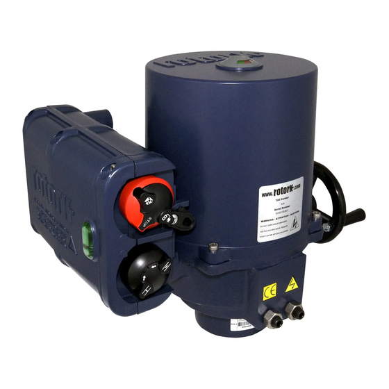
- Page 1 ROMpak Series Installation Manual Valve Actuators Keeping the World Flowing...
-
Page 2: Table Of Contents
Contents Section Section Page Page CHANGE PHOTO CHANGE PHOTO Health and safety Introduction PHOTO CAN BE PHOTO CAN BE Operating by hand Section Title DELETED IF TWO DELETED IF TWO Electrical operation Content COLUMNS OF COLUMNS OF Content Indication Content CONTENTS ARE CONTENTS ARE Mounting the actuator... -
Page 3: Health And Safety Introduction
Health and Safety This manual is produced to enable a Every Rotork actuator has been fully tested before leaving the factory to give years of trouble free competent user to install, operate, operation providing it is correctly commissioned, adjust and inspect Rotork ROMpak valve installed and sealed. - Page 4 The mechanism will automatically disengage when the actuator is operated electrically. CAUTION: With respect to handwheel operation of Rotork electric actuators, under no circumstances should any additional lever device such as a wheel key or wrench be applied to develop more force when closing or opening...
-
Page 5: Electrical Operation Content
Electrical Operation Local Control With the red selector positioned at Local (anti- clockwise) the adjacent black knob can be turned to select Open or Close. To stop, turn the red knob clockwise. Local Control Knob When Local is selected on the Red selector the black knob can be turned to open and close the actuator. - Page 6 Indication Local Indicator On the top cover a continuous position indicator will rotate and change colour to indicate valve position. In the standard configuration green is closed and red is open. Located on the side face of the control Pak, three LED’s also indicate valve position and status.
-
Page 7: Mounting The Actuator Content
Mounting the Actuator The ROMpak actuator is suitable for quarter turn non thrust applications. Ensure the valve is secure before fitting the actuator, as the combination may be top heavy and therefore unstable. A suitable mounting flange conforming to ISO 5211 or USA Standard MSS SP101 must be fitted to the valve. - Page 8 Setting the Actuator Stop Bolts Stop Bolts Adjusting the stop bolts in and out will increase or decrease the valve travel. It is recommended that stop bolt adjustment be carried out by the valve maker/supplier before the valve is fitted into the pipe work.
-
Page 9: Cable Connections Content
Pak. Rotork advise using the transit plug entry first for wiring connections. If this entry is not used, a steel or brass blanking plug must be installed to maintain sealing of the ROMPak enclosure. - Page 10 Cable Connections Connecting to the power terminals Refer to the wiring diagram supplied. Three-Phase Connection Three power and an earth termination posts are available using the 4 mm screws and washers provided. The terminal identification is moulded into the housing adjacent to the termination posts. The cable connections must be secured using an appropriate sized ring tag connector.
- Page 11 Commissioning WARNING: Ensure all power supplies are isolated before removing actuator cover. Caution is required when removing cover as motor and heater may be hot. On actuators with single- phase supplies the motor start capacitor may retain a hazardous residual charge. The ROMpak is factory set to operate 90º...
- Page 12 Commissioning Type 1 - Cam adjustment for plastic cam ROMpak 1/A The following instruction is only applicable for clockwise to close valves. To set the open position: Turn power off. Use manual override to turn valve to the fully open position. Remove cover.
- Page 13 Commissioning Type 2 - Cam adjustment for ROMpak 1/A The following instruction is only applicable to situation that the valve is clockwise for closing (from the top view). Turn power off. Remove cover and unscrew the self-locking nut anticlockwise twice approximately 60 degree each time from position A to B as shown in picture D by inserting 4.0 mm Allen (hex.) key Picture D: Travel from position A to B is about...
- Page 14 Commissioning Type 3 - Cam adjustment for metal cam ROMpak A and ROMpak 1-6 ROM 2-7 The following instruction is only applicable to situation that the valve is clockwise for closing (from the top view). To set the Open position Turn power off.
- Page 15 Commissioning For Anti-Clockwise to close actuators Open Switch Setting PCB Function Switch 7 ON. Move the valve to the fully clock wise open position. Locate cam TC2 and adjust until switch LS2 just The indicator flag can be rotated 90º by removing operates.
- Page 16 Commissioning Initialisation - for actuators fitted with an Potentiometer adjustment (if fitted) option card and potentiometers. The potentiometer is factory set to operate over 90 degrees and should not require adjustment. It may Mounted above the position travel cams is a be necessary to adjust the potentiometer if the stop potentiometer used as a position reference for the bolts have been adjusted or the pot has slipped out...
- Page 17 Commissioning Setting of Control Function Switches The 12 switch selector on the main PCB enables different control functions to be chosen Function Switch OFF Switch ON Switch Close Green / Open Red Close Red / Open Green Single phase supply Three phase supply Normally Open Normally Closed...
- Page 18 Commissioning Optional Extras Current position transmitter (CPT) and Folomatic combined PCB. The CPT gives continuous indication of valve position and is factory set to give 4 mA Close 20 mA Open. Folomatic Proportional Control The Folomatic proportional control sets the valve position relating to an input signal.
-
Page 19: Maintenance And Troubleshooting
Maintenance and Troubleshooting Troubleshooting Every Rotork actuator has been fully tested before dispatch to give years of trouble free operation Actuator Fails to Start on Local Control providing it is installed, sealed and commissioned Set the selector switch to local control and switch in accordance with the instructions given in this the power on. - Page 20 PUB008-006-00 As part of a process of on-going product development, Rotork reserves the right to amend and change specifications without prior notice. Published data may be subject Issue 07/18 to change. For the very latest version release, visit our website at www.rotork.com The name Rotork is a registered trademark.
Need help?
Do you have a question about the ROMpak Series and is the answer not in the manual?
Questions and answers