Table of Contents
Advertisement
Advertisement
Table of Contents

Related Manuals for rotork Master Station


Summary of Contents for rotork Master Station
- Page 1 Safe Use, Installation and Maintenance Manual...
- Page 2 Rotork Master Station Master Station Safe Use, Installation and Maintenance Manual...
-
Page 3: Table Of Contents
This manual contains important safety information. Please ensure it is thoroughly read and understood before installing, operating or maintaining the equipment. This manual is produced to enable a competent user to install, operate, adjust and inspect the Rotork Master Station. These user instructions are provided subject to the following conditions and restrictions: This document contains information of a proprietary nature belonging to Rotork. -
Page 4: Introduction
FCUs or the Master Station. For remote access, the Master Station has built-in web pages mirroring the local display. There are two different field networks available as AIMs for the Master Station and up to four AIMs can be fitted to the Master Station. - Page 5 1. Introduction continued Work Station Laptop Off-site Connection H O S T E T H E R N E T N E T W O R K C L A S S I C Including 3 Party 2-Wire Current Loop Field Devices Electro-hydraulic Valve...
-
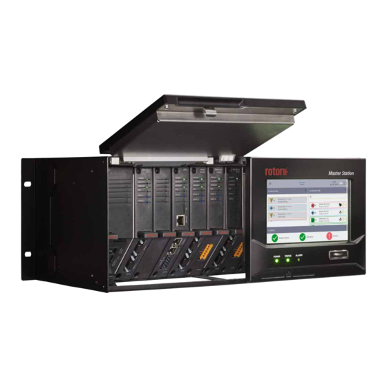
Page 6: Know Your Rotork Master Station
2. Know your Rotork Master Station Touch screen display Hot Standby and Dual Each side of a hot standby or dual Master Station has a display module to interface with that side of the Master Station. Hot Standby and Dual... - Page 7 Slot 2 Slot 3 Slot 4 Hot Standby The hot standby Master Station contains a duplicate set of modules on the right hand side. The position of AIMs fitted on the right must match the modules fitted on the left. Dual The dual Master Station has two separate sides that can accommodate different modules.
- Page 8 AIMs fitted to your unit. User connections Master Station provides front access for all the user connections, including power, and field network connections to the Pakscan Classic module (P4720) or Modbus RTU module (P4724).
- Page 9 2. Know your Rotork Master Station continued Single Rotork Master Station Optional Optional For RS-485 Serial Data For RS-232 Serial Data 9-way Female D-type 9-way Female D-type RS-485 Connections RS-232 Connections Connect to Host Serial 1. Connect to Host Serial 2.
- Page 10 'Y' loom connector. Port B IN Port B OUT Screen CONNECTOR Data – Data + Port A IN Connect to both Port A OUT sides of the Screen Signal Common CONNECTOR Master Station. Master Station Safe Use, Installation and Maintenance Manual...
- Page 11 2. Know your Rotork Master Station continued Dual Rotork Master Station Optional Optional For RS-232 Serial Data For RS-485 Serial Data 9-way Female D-type 9-way Female D-type RS-232 Connections RS-485 Connections Connect to Host Serial 2. Connect to Host Serial 1.
-
Page 12: Rotork Master Station Technical Datasheet
Option: The Master Station has 4 AIM (Add In Module) slots that can be fitted with host or field network modules. Only one host AIM can be fitted; only one Modbus RTU AIM can be fitted; up to two Pakscan Classic AIMs can be fitted. - Page 13 Can be configured fully via Local touch screen Interface or built in web pages. Each Master Station contains at least 1 local touch screen interface – 2 in the case of a hot standby or dual unit. • Size: 7.0”...
-
Page 14: Health And Safety
Work undertaken must be carried out in accordance with the instructions in this and any other relevant manuals. If the Master Station is used in a manner not specified in this manual and any other Rotork manual, the protection provided by the Master Station may be impaired. -
Page 15: Installation
Master Station. • Free standing: on a horizontal surface. In all cases the Master Station should be located in a way that permits easy access to the touch screen interface and disconnection of the power supply. CAUTION: Do not obstruct the air cooling outlet and inlet vents on the top and underside. Free flow of air around the Master Station must be maintained, especially at high ambient temperatures. - Page 16 Every Master Station includes a nameplate detailing serial number and model number. The serial number uniquely identifies the Master Station and can be used by the Rotork factory to trace the manufacturing details of the unit. This is a useful reference for upgrades and spares enquiries.
-
Page 17: Basic Commissioning
PC to open the home page of the Master Station. If the IP address of the Master Station has been changed, this can be viewed via the touch screen interface in the Master Station settings. The Laptop/PC must be configured within the same IP range and subnet mask to communicate. - Page 18 A and side B. These must be different for a dual Master Station. A hot standby Master Station is normally configured for the same Modbus address on both sides but this is not mandatory.
- Page 19 FCUs supported by the Master Station or the range of FCU addresses in use. The table below advises what value to set depending on the Master Station FCU count. FCU count is shown on the Master Station test certificate.
- Page 20 A single Master Station requires only side A to be configured. A dual Master Station requires side A to be configured on side A and side B to be configured on side B. Hot standby Master Station requires side A and side B to be configured.
- Page 21 Serial ports is one set to RS-485 and the other set to RS-232. This makes initial communication testing possible without the need to adjust settings. Serial 1 and Serial 2 are identical and have the same priority in the Master Station therefore it does not matter which is used. The...
- Page 22 3. Unscrew the top and bottom fixings that hold the module in place. Screws are captive so will not unscrew fully. 4. Pull the tab outwards away from the Master Station to remove the module. It is important to pull outwards in a smooth linear motion to avoid twisting the module and potentially damaging PCB components.
- Page 23 Lowest FCU Scan Address Highest FCU Scan Address must be set*. If multiple classic field networks are installed, address ranges must not overlap ensuring each FCU has a unique address on the Master Station. Loop Speed must be configured to an appropriate value taking into account loop distance, cable specification and number of connected FCUs.
- Page 24 *These settings define how many FCUs (field control units) the Modbus RTU AIM should scan for and which addresses they are. The individual FCUs must be configured with a unique address within this range. Master Station Safe Use, Installation and Maintenance Manual...
- Page 25 6. Basic Commissioning continued In order for the Master Station to identify Modbus FCUs, a Device File must be created that defines the FCU type code against the Modbus address of each FCU. The Device File is a plain text file in a CSV (Comma Separated Values) format.
-
Page 26: Environmental
Damaged fuses must be replaced with the fuse type mentioned above and must be pre-certified types to the IEC 60127 or ANSI/UL 248 series. 9. Vibration and Shock The Rotork Master Station is suitable for installation in locations where vibration and shock severity does not exceed the following: Type Level Vibration Frequency range 5 to 150 Hz, acceleration 0.7 gn peak... -
Page 27: Safety
If the Master Station cannot be installed immediately, store it in its original box in a dry place. In most cases it is not necessary to remove the Master Station modules during commissioning and installation. The exception is where the serial physical layer requires changing from RS-232 to RS-485. Rotork cannot accept responsibility for damage caused on-site during removal or replacement of these modules by untrained personnel. - Page 28 As part of a process of on-going product development, Rotork reserves the right to amend and change specifications without prior notice. Published data may be subject to change. For the very latest version release, visit our website at www.rotork.com PUB059-050-00 The name Rotork is a registered trademark.
Need help?
Do you have a question about the Master Station and is the answer not in the manual?
Questions and answers