Comtech EF Data CRS-170A Installation And Operation Manual
L-band 1:1 redundancy switch accessory product for use only with comtech ef data cdm-625/a, cdm-840, cdm-750, cdm-760, cdm-570l, cdm-700, cdm-710, cdm-710g, cdm-600l (clm-9600l), and sdm-300l3 modems
Hide thumbs
Also See for CRS-170A:
- Installation and operation manual (154 pages) ,
- Installation and operation manual (176 pages)
Table of Contents
Advertisement
Quick Links
CRS-170A
L-Band 1:1 Redundancy Switch
Installation and Operation Manual
Accessory Product for use only with Comtech EF Data
CDM-625/A, CDM-840, CDM-750, CDM-760, CDM-570L, CDM-700, CDM-710,
CDM-710G, CDM-600L (CLM-9600L), and SDM-300L3 Modems
(Modem Firmware and Hardware Requirements Apply)
IMPORTANT NOTE: The information contained in this document supersedes all previously published
information regarding this product. Product specifications are subject to change without prior notice.
Part Number MN/CRS170A.IOM
Revision 10
Advertisement
Table of Contents

Related Manuals for Comtech EF Data CRS-170A


Summary of Contents for Comtech EF Data CRS-170A
- Page 1 CRS-170A L-Band 1:1 Redundancy Switch Installation and Operation Manual Accessory Product for use only with Comtech EF Data CDM-625/A, CDM-840, CDM-750, CDM-760, CDM-570L, CDM-700, CDM-710, CDM-710G, CDM-600L (CLM-9600L), and SDM-300L3 Modems (Modem Firmware and Hardware Requirements Apply) IMPORTANT NOTE: The information contained in this document supersedes all previously published information regarding this product.
- Page 3 CDM-710G, CDM-600L (CLM-9600L), and SDM-300L3 Modems (Modem Firmware and Hardware Requirements Apply) Part Number MN/CRS170A.IOM Revision 10 Copyright © 2013 Comtech EF Data. All rights reserved. Printed in the USA. Comtech EF Data, 2114 West 7th Street, Tempe, Arizona 85281 USA, 480.333.2200, FAX: 480.333.2161...
- Page 4 BLANK PAGE...
-
Page 5: Table Of Contents
European Union RoHS Directive (2002/95/EC) .................. xv European Union Telecommunications Terminal Equipment Directive (91/263/EEC) ....... xv CE Mark .............................. xv Product Support ..........................xv Comtech EF Data Headquarters ....................... xvi Warranty Policy ..........................xvi Limitations of Warranty ......................... xvi Exclusive Remedies ..........................xvii CHAPTER 1. - Page 6 Configuring CDM-700s/CDM-710s/CDM-710Gs for 1:1 Redundancy ........3–13 3.6.1 IP Redundancy Configuration ....................3–14 3.6.2 Non-IP Redundancy Configuration ..................3–14 CDM-600L (CLM-9600L) Operation in 1:1 Redundancy ............3–15 SDM-300L3 Operation in 1:1 Redundancy ................. 3–15 CRS-170A Switch DIP Settings ................... 3–17...
- Page 7 CABLES AND CONNECTIONS ................4–1 Overview ........................... 4–1 Cabling to the CDM-625/A....................4–3 4.2.1.1 CRS-170A CDM-625/A Control and IF Interface Cabling Kit KT-0000160 ....4–3 4.2.2 Modem-to-Switch Control Interface Connection ..............4–4 4.2.3 Modem-to-Switch IF Interface Connection ................4–5 4.2.3.1...
- Page 8 CRS-170A L-Band 1:1 Redundancy Switch Revision 10 Table of Contents MN/CRS170A.IOM 4.5.4.3 G.703 Unbalanced Interface Example ................4–34 4.5.4.4 10/100 Ethernet Interface Example................4–35 Cabling to the CDM-700 ....................4–37 4.6.1 Modem-to-Switch Control and IF Interface Connection ............4–37 4.6.2 Modem-to-User Data Interface Kit and Connection Examples ..........
- Page 9 Modem to CRS-170A, L-Band Coaxial Cable, RoHS, Type ‘N’ 50Ω ........A-12 A.3.2 Modem to CRS-170A or User, 70/140 MHz Coaxial Cable, RoHS, Type ‘BNC’ 75 Ω ..A-13 A.3.3 Modem to User, Splitter Cable, (2X) DB-25M DB-25F ..........A-14 A.3.4...
- Page 10 Figure 3-2. CDM-570L Configuration Interfaces ..................3–9 Figure 3-3. CDM-570L CLI 1:1 Redundancy Configuration screen ............3–11 Figure 3-4. CRS-170A Antenna Side – DIP Switches ................3–17 Figure 4-1. CDM-625/A Modem-to-Switch Control Connections ............. 4–4 Figure 4-2. CDM-625/A Modem-to-Switch L-Band IF Connections ............4–5 Figure 4-3.
- Page 11 Figure 4-48. CDM-600L (CLM-9600L) Block Diagram: Cable Connections ..........4–57 Figure 4-49. SDM-300L3 Block Diagram: Cable Connection ..............4–58 Figure 5-1. CRS-170A – Modem and Antenna Side Connectors ............... 5–1 Figure A-1. Universal Control Cable (CEFD P/N CA/WR9378-4) .............. A-3 Figure A-2.
- Page 12 CRS-170A L-Band 1:1 Redundancy Switch Revision 10 Table of Contents MN/CRS170A.IOM BLANK PAGE...
-
Page 13: Preface
PREFACE About this Manual This manual provides installation and operation information for the Comtech EF Data CRS-170A L-Band 1:1 Redundancy Switch. This is a technical document intended for the persons responsible for the operation and maintenance of the CRS-170A and its supported modems. -
Page 14: Conventions And References
Patents and Trademarks See all of Comtech EF Data's Patents and Patents Pending at http://patents.comtechefdata.com. Comtech EF Data acknowledges that all trademarks are the property of the trademark owners. Warnings, Cautions and Notes A WARNING informs you about a possible hazard that MAY CAUSE DEATH or SERIOUS INJURY. -
Page 15: Recommended Standard Designations
4.5 Watts, and draws a maximum of 250 mA at +12 volts DC and 120 mA at -12 volts DC. The power supply current is, in all circumstances, supplied by either a single Comtech EF Data modem, or a pair of these modems. -
Page 16: Equipment Connection
Preface MN/CRS170A.IOM Equipment Connection THE CRS-170A IS DESIGNED FOR OPERATION ONLY WITH THE COMTECH EF DATA PRODUCTS LISTED IN THIS MANUAL UNDER ‘RELATED DOCUMENTS’. THESE PRODUCTS SUPPLY DC OPERATING CURRENT (ELECTRONICALLY FUSED AND PROTECTED) AND CONTROL SIGNALS FOR THE CORRECT FUNCTIONING OF THIS SWITCH. -
Page 17: European Union Low Voltage Directive (Lvd) (2006/95/Ec)
In accordance with the European Union Telecommunications Terminal Equipment Directive 91/263/EEC, do not directly connect the unit to the Public Telecommunications Network. CE Mark Comtech EF Data declares that the unit meets the necessary requirements for the CE Mark. Product Support For all product support, please call: +1.240.243.1880... -
Page 18: Comtech Ef Data Headquarters
The warranty does not apply to any part of a product that has been installed, altered, repaired, or misused in any way that, in the opinion of Comtech EF Data Corporation, would affect the reliability or detracts from the performance of any part of the product, or is damaged as the result of use in a way or with equipment that had not been previously approved by Comtech EF Data Corporation. -
Page 19: Exclusive Remedies
The warranty does not cover damage or loss incurred in transportation of the product. The warranty does not cover replacement or repair necessitated by loss or damage from any cause beyond the control of Comtech EF Data Corporation, such as lightning or other natural and weather related events or wartime environments. - Page 20 CRS-170A L-Band 1:1 Redundancy Switch Revision 10 Preface MN/CRS170A.IOM Notes: xviii...
-
Page 21: Chapter 1. Introduction
Overview Figure 1-1. CRS-170A L-Band 1:1 Redundancy Switch The CRS-170A L-Band 1:1 Redundancy Switch module, shown in Figure 1-1, is an L-Band Tx-Rx IF signal switch designed for use with L-Band satellite modems in a 1:1 configuration. The Tx (transmit) side switches four modem output signals that are multiplexed onto the transmit coaxial cable: 950-2250 MHz L-band transmit RF;... -
Page 22: Table 1-1. Crs-170A Application Summary
Order modems with Type ‘N’ connectors. Firmware updates are free and may be downloaded from the Comtech EF Data web page. If a modem does not meet the hardware requirements, contact CEFD – hardware revision upgrades must be performed at CEFD ®... -
Page 23: 1.1.1 Modem Side Connectors
Similarly, the SDM-300L3 requires an SMS-301 switch together with the CRS-170A. In both cases, the CRS-170A is controlled by the supporting data switch, and places the “A” or “B” modem RF online to match the data switch state. The CDM-600L (CLM-9600L) modems supply redundant power to the CRS-170A through the CRS-150. -
Page 24: 1.1.2 Antenna Side Connectors
MN/CRS170A.IOM 1.1.2 Antenna Side Connectors Two 50Ω female Type ‘N’ connectors on the antenna side of the CRS-170A L-Band 1:1 Redundancy Switch module provide the coaxial cable connections to the outdoor transmit and receive equipment (BUC and LNB). Refer to Figure 1-3 and its accompanying table for details (this image depicts the Rev. -
Page 25: Operation With Cdm-625/A, -840, -750, -760, -570L, -700, -710, -710G Modems
OR’d so that the switch remains active if power is lost from one of the modems. Mode Switches – The Mode DIP switches, located on the antenna side of the CRS-170A, allow the switch to operate in two different modes: Normal (Intelligent Controller) Mode and SDM-300L/CDM-600L (Dumb Controller) Mode. - Page 26 Modem Unit faults or Receive Traffic faults; Modem Unit faults or Transmit Traffic faults; or all three. Also located on the antenna side of the CRS-170A are two green LEDs that indicate which modem is Online. With the ‘bridging’ architecture of the CRS-170A (whereby identical terrestrial data traffic signals are routed to both Online and Offline modems), the redundancy controller can avoid unnecessary switchovers.
-
Page 27: 1:1 Ip Redundancy Data Switching - Functional Description
CRS-170A L-Band 1:1 Redundancy Switch Revision 10 Introduction MN/CRS170A.IOM 1.2.1.1 1:1 IP Redundancy Data Switching – Functional Description 1.2.1.1.1 CDM-570L (with Optional IP Module) – Managed Switch or Router Modes • Do not use the M&C Ethernet port (bottom RJ-45 connector) when the optional IP Module is installed. -
Page 28: Figure 1-4. Cdm-570L 1:1 Ip Redundancy Router Mode - 'A' Online
CRS-170A L-Band 1:1 Redundancy Switch Revision 10 Introduction MN/CRS170A.IOM Figure 1-4. CDM-570L 1:1 IP Redundancy Router Mode – ‘A’ Online 1–8... -
Page 29: Cdm-625/A, -750, -760, -700, -710, -710G Managed Switch Mode
CRS-170A L-Band 1:1 Redundancy Switch Revision 10 Introduction MN/CRS170A.IOM Figure 1-5. CDM-570L 1:1 IP Redundancy Router Mode – ‘B’ Online (Switchover) 1.2.1.1.2 CDM-625/A, -750, -760, -700, -710, -710G Managed Switch Mode A standard, user-provided Ethernet Layer 2 Switch is needed when a CDM-625/A, CDM-750, CDM-760, CDM-700, CDM-710, or CDM-710G modem is configured for Managed Switch Mode (also known as “Ethernet Bridge Mode”) terrestrial traffic. -
Page 30: Figure 1-6. Cdm-625/A, -750, -760, -700, -710, -710G 1:1 Ip Redundancy Managed Switch Mode
CRS-170A L-Band 1:1 Redundancy Switch Revision 10 Introduction MN/CRS170A.IOM Any new packets arriving destined for that MAC address will be forwarded only out the port identified in the CAM table. Most switch CAM tables do have a flush or timeout value, but is normally set to a very high number to limit the amount of times the switch has to broadcast a packet out all ports. -
Page 31: Figure 1-7. Cdm-625/A, -750, -760, -700, -710, -710G 1:1 Ip Redundancy Managed Switch Mode
CRS-170A L-Band 1:1 Redundancy Switch Revision 10 Introduction MN/CRS170A.IOM Figure 1-7. C DM-625/A, -750, -760, -700, -710, -710G 1: 1 IP R edundancy Managed S witc h Mode – S witc hover As shown in Figure 1-7, in the event of a fault occurring on the Online Modem ‘A’, the following will occur: •... -
Page 32: Cdm-625/A (With Optional Ip Packet Processor) - Router Mode
CRS-170A L-Band 1:1 Redundancy Switch Revision 10 Introduction MN/CRS170A.IOM Note the following: 1. The Managed Switch Mode method of redundancy is intended to be equivalent to pulling the Ethernet cable from one port and putting it into a different port on the same switch. -
Page 33: Figure 1-8. Cdm-625/A 1:1 Ip Redundancy Router Mode – 'A' Online
CRS-170A L-Band 1:1 Redundancy Switch Revision 10 Introduction MN/CRS170A.IOM Whichever modem is online will assume the Traffic IP. When there is a switchover to the backup modem, this modem will now assume the Traffic IP. Per Figure 1-9, the backup modem will also broadcast a “gratuitous ARP” which will tell all local devices to now associate a new MAC address for the Traffic IP 172.18.10.20. -
Page 34: 1.2.2 Operation With Cdm-600L (Clm-9600L) And Sdm-300L3
10MHz reference signals, DC power for the BUC and LNB, and FSK signaling to the BUC are switched in the CRS-170A under control of the CRS-150. In the case of an equipment failure, automatic switching takes place to protect the traffic circuit. - Page 35 LED will illuminate on the front of the CRS-150 to indicate whether the ‘A’ or ‘B’ unit is online, and a green LED on the antenna side of the CRS-170A will indicate the same status. DIP switches on the CRS-170A’s front panel are set to establish modem-specific operation. With the CDM-600L (CLM-9600L), place the Mode switch in the SDM-300L/CDM-600L (CLM-9600L) position and push the Switch Condition switches to the OFF position.
-
Page 36: Operation With Sdm-300L3 And Sms-301
IF signals, 10MHz reference signals, DC power for the BUC and LNB, and FSK signaling to the BUC are switched in the CRS-170A under control of the SMS-301. In the case of an equipment failure, automatic switching takes place to protect the traffic circuit. Consult the Comtech EF Data SMS-301 Redundancy Switch Installation and Operation Manual for detailed information on operation of the SMS-301. -
Page 37: Summary Of Specifications
CRS-170A L-Band 1:1 Redundancy Switch Revision 10 Introduction MN/CRS170A.IOM Summary of Specifications Equipment Type L-Band 1:1 Redundancy Switch Manufacturer Comtech EF Data, Tempe, Arizona Supported Comtech EF Data Modems • CDM-625/A with/without optional IP Packet Processor • CDM-840 Remote Router •... - Page 38 CRS-170A L-Band 1:1 Redundancy Switch Revision 10 Introduction MN/CRS170A.IOM Weight 1.1lbs (0.5kg) Dimensions [excluding connectors] 1.7 H x 5.7 W x 4.1 D inches (43 H x 143 W x 104 D mm) 19-inch rack mounting kit available. Power requirements + 12 volts DC @ 130 mA (max) •...
-
Page 39: Chapter 2. Installation
Chapter 2. INSTALLATION Unpacking and Inspection The CRS-170A L-Band 1:1 Redundancy Switch module and its Installation and Operation Manual were packaged and shipped in a reusable cardboard carton containing protective foam spacing. This equipment contains parts and assemblies sensitive to damage by Electrostatic Discharge (ESD). -
Page 40: Mounting
Mounting Figure 2-1. KT/10254 Mounting Panel Kit (for horizontal or vertical mounting) The CRS-170A is designed to be freestanding, or mounted in the rear of the rack containing the modems using the available Comtech EF Data Mounting Panel Kit KT/10254. -
Page 41: Chapter 3. Modem And Switch Configuration
Chapter 3. MODEM AND SWITCH CONFIGURATION Overview In order to avoid damage to the modems and CRS-170A switch, it is important to follow this sequence of configuration: First, configure the modems for 1:1 redundant operation as outlined in this •... - Page 42 CRS-170A L-Band 1:1 Redundancy Switch Revision 10 Modem and Switch Configuration MN/CRS170A.IOM BLANK PAGE 3–2...
-
Page 43: Configuring Cdm-625/As For 1:1 Redundancy
CRS-170A L-Band 1:1 Redundancy Switch Revision 10 Modem and Switch Configuration MN/CRS170A.IOM Configuring CDM-625/As for 1:1 Redundancy • CDM-625A Advanced Satellite Modem Installation and Operation Manual (CEFD P/N MN-CDM625A) • CDM-625 Advanced Satellite Modem Installation and Operation Manual (CEFD P/N MN-CDM625) The CDM-625/A Advanced Satellite Modem automatically detects if it is connected to a 1:1 redundancy system –... -
Page 44: Carrier-In-Carrier® Redundancy Configuration
CRS-170A L-Band 1:1 Redundancy Switch Revision 10 Modem and Switch Configuration MN/CRS170A.IOM Dedicated Management Port Mode is not configurable for use when the optional IP Packet Processor is installed and enabled. With the IP Packet Processor enabled, as a means to avoid Ethernet Networking Loops, only one of the CDM-625’s four 10/100 Ethernet Ports is used for each modem at any given time. -
Page 45: Cdm-840 Operation In 1:1 Redundancy
CRS-170A L-Band 1:1 Redundancy Switch Revision 10 Modem and Switch Configuration MN/CRS170A.IOM CDM-840 Operation in 1:1 Redundancy CDM-840 Remote Router Installation and Operation Manual (CEFD P/N MN-CDM840) The CDM-840 Remote Router automatically detects if it is connected to a 1:1 redundancy system. - Page 46 CRS-170A L-Band 1:1 Redundancy Switch Revision 10 Modem and Switch Configuration MN/CRS170A.IOM Notes: 3–6...
-
Page 47: Cdm-750 Or Cdm-760 Operation In 1:1 Redundancy
CRS-170A L-Band 1:1 Redundancy Switch Revision 10 Modem and Switch Configuration MN/CRS170A.IOM CDM-750 or CDM-760 Operation in 1:1 Redundancy • CDM-750 Advanced High-Speed Trunking Modem Installation and Operation Manual (CEFD P/N MN-CDM750) • CDM-760 Advanced High-Speed Trunking Modem Installation and Operation... - Page 48 CRS-170A L-Band 1:1 Redundancy Switch Revision 10 Modem and Switch Configuration MN/CRS170A.IOM Notes: 3–8...
-
Page 49: Configuring Cdm-570Ls For 1:1 Redundancy
MN/CRS170A.IOM Configuring CDM-570Ls for 1:1 Redundancy CDM-570/CDM-570L/CDMR-570L Satellite Modem Installation and Operation Manual (CEFD P/N MN/CDM570L.IOM) For correct operation of the CRS-170A, the CDM-570L Satellite Modems must have the following installed: Base Modem Firmware Version 1.6.7 (or higher) • IP Module Firmware Version 1.5.4.2 (or higher) •... -
Page 50: Ip Redundancy Configuration
The t wo modems will need a n E thernet c onnection t o eac h ot her t hrough a Lay er 2 switch (preferred) or hub. Before connecting the modems to the CRS-170A, you will need t o first configure the following modem IP module settings: Redundancy Configuration ... -
Page 51: Non-Ip Redundancy Configuration
CRS-170A L-Band 1:1 Redundancy Switch Revision 10 Modem and Switch Configuration MN/CRS170A.IOM Figure 3-3. CDM-570L CLI 1:1 Redundancy Configuration screen All configuration changes can only be made to the Online Modem and will require you to “Save Parameters to permanent storage” to ensure the configuration change is also applied to the Backup Modem. - Page 52 CRS-170A L-Band 1:1 Redundancy Switch Revision 10 Modem and Switch Configuration MN/CRS170A.IOM Notes: 3–12...
-
Page 53: Configuring Cdm-700S/Cdm-710S/Cdm-710Gs For 1:1 Redundancy
• ► Firmware Version 5.1.1 (or higher) If the modems do not meet this requirement, contact Comtech EF Data. Firmware updates are free and may be downloaded from the CEFD web page. Hardware revision upgrades must be performed at CEFD. -
Page 54: Ip Redundancy Configuration
Verify that one modem is ONLINE by the front panel LEDs; also verify that the ONLINE LEDs for the CRS-170A indicate the same online state as the modems. All configuration changes can only be made to the Online Modem and will require you to “Save Parameters to permanent storage”... -
Page 55: Cdm-600L (Clm-9600L) Operation In 1:1 Redundancy
• Hardware Revision 3 • If the modems do not meet this requirement, contact Comtech EF Data. Firmware updates are free and may be downloaded from the CEFD web page. Hardware revision upgrades must be performed at CEFD. SDM-300L3 Operation in 1:1 Redundancy SDM-300L3 Satellite Modem Installation and Operation Manual (CEFD P/N MN/CLM9600L.IOM) - Page 56 CRS-170A L-Band 1:1 Redundancy Switch Revision 10 Modem and Switch Configuration MN/CRS170A.IOM Notes: 3–16...
-
Page 57: Crs-170A Switch Dip Settings
Figure 3-4 shows the DIP switches for setting the ‘Mode’ and ‘Switch Conditions’ on the Antenna Side of the CRS-170A L-Band 1:1 Redundancy Switch (towards the BUC and LNB). The difference of the ‘Mode’ DIP switch silk screening between the original and current (i.e., Rev. A and later) versions of the CRS-170A is illustrated here. -
Page 58: Table 3-1. Crs-170A Dip Switch Settings
CRS-170A L-Band 1:1 Redundancy Switch Revision 10 Modem and Switch Configuration MN/CRS170A.IOM Table 3-1. CRS-170A DIP Switch Settings ‘Mode’ DIP Settings ‘Switch Conditions’ DIP Settings Left Right Left Right Modem Result Switch Switch Switch Switch CDM-625/A Down Switchover upon a Unit... -
Page 59: Chapter 4. Cables And Connections
(one Redundant modem, one Traffic modem), you must also purchase a redundancy kit tailored to that modem choice. This kit provides – in addition to the CRS-170A L-Band 1:1 Redundancy Switch module – all cables and components required for interconnection of the redundant configuration to various interfaces (i.e., control, IF, and data), excluding Ethernet,... - Page 60 CRS-170A L-Band 1:1 Redundancy Switch Revision 10 Cables and Connections MN/CRS170A.IOM BLANK PAGE 4–2...
-
Page 61: Cabling To The Cdm-625/A
Here, Figure 4-1 through Figure 4-3 show how to connect a pair of CDM-625/A modems together with the CRS-170A L-Band 1:1 Redundancy Switch module; the table that accompanies each figure lists the cables provided in KT-0000160 for this initial setup. -
Page 62: Modem-To-Switch Control Interface Connection
4.2.2 Modem-to-Switch Control Interface Connection When connecting the Control cable between the CRS-170A and the modems, ensure that screw locks on the ‘D’ type connectors are securely fastened. This will prevent the accidental unmating of the cable, particularly when a standby unit is being removed or replaced. -
Page 63: Modem-To-Switch If Interface Connection
Modem-to-Switch IF Interface Connection EXAMPLE: The Tx IF from ‘ Modem A’ connects to the Tx IF port ‘J5 Tx A’ on the CRS-170A; similarly, the Tx IF from ‘Modem B’ connects to the Tx IF port ‘J6 Tx B’ on the CRS-170A. -
Page 64: Modem-To-Switch L-Band Tx / 70/140 Mhz Rx If Interface Connection
CRS-170A L-Band 1:1 Redundancy Switch Revision 10 Cables and Connections MN/CRS170A.IOM 4.2.3.2 Modem-to-Switch L-Band Tx / 70/140 MHz Rx IF Interface Connection If the Tx IF is L-Band and the Rx IF is 70/140MHz, additional items may be purchased for this option, as shown here in Figure 4-3. -
Page 65: Modem-To-User Data Interface Connections And Examples
CRS-170A L-Band 1:1 Redundancy Switch Revision 10 Cables and Connections MN/CRS170A.IOM 4.2.4 Modem-to-User Data Interface Connections and Examples Appendix A. CABLE DRAWINGS The data cables and components identified in each of the examples that follow in this section must be purchased separately, as required. -
Page 66: Eia-422/232, V.35 Interface Example
CRS-170A L-Band 1:1 Redundancy Switch Revision 10 Cables and Connections MN/CRS170A.IOM 4.2.4.1 EIA-422/232, V.35 Interface Example CEFD Part No. Description CA/RB10461-1 Cable – 1:1 ‘Y’ Splitter, (2X) DB-25M DB-25F Figure 4-5. CDM-625/A EIA-422/232, V.35 1:1 Example 4.2.4.2 HSSI Interface Example CEFD Part No. -
Page 67: Asi Interface Example
CRS-170A L-Band 1:1 Redundancy Switch Revision 10 Cables and Connections MN/CRS170A.IOM 4.2.4.3 ASI Interface Example KT/12579 ASI 75Ω Interface Kit CEFD Part No. Description CA/BNC75OHM Cable – IF BNC, 75Ω, 1’ RF/SA32KC-IN/OUT Combiner – 2-way w/Bracket, 0.25-300 MHz, 75Ω BNC Figure 4-7. -
Page 68: Quad E1 Interface Example
2. If you desire three or four separate ports of E1 (i.e., Port 1 and Port 2 -or- Port 3 and Port 4), then optional adapter cables may be purchased from Comtech EF Data to adapt the G.703 Balanced and Auxiliary G.703 DB-9F single connector pairs to outgoing Quad E1 connector pairs as follows: Converts (1) 9-pin Type ‘D’... -
Page 69: G.703 Balanced Interface Example
CRS-170A L-Band 1:1 Redundancy Switch Revision 10 Cables and Connections MN/CRS170A.IOM 4.2.4.5 G.703 Balanced Interface Example CEFD Part No. Description CA-0000071 Cable – 1:1 ‘Y’ Splitter, (2X) DB-9M DB-9F, 8” Figure 4-9. CDM-625/A G.703 Balanced 1:1 Example 4.2.4.6 G.703 Unbalanced Interface Example KT/10553-1 G.703 Unbalanced Interface Kit... -
Page 70: Overhead Interface Example
CRS-170A L-Band 1:1 Redundancy Switch Revision 10 Cables and Connections MN/CRS170A.IOM 4.2.4.7 Overhead Interface Example CEFD Part No. Description CA-0000070 Cable – 1:1 ‘Y’ Splitter, (2X) HD-44M HD-44F, 8” Figure 4-11. CDM-625/A Overhead 1:1 Example 4.2.4.8 Engineering Service Channel (ESC) Interface Example CEFD Part No. -
Page 71: 10/100 Ethernet Interface Examples
CRS-170A L-Band 1:1 Redundancy Switch Revision 10 Cables and Connections MN/CRS170A.IOM 4.2.4.9 10/100 Ethernet Interface Examples 4.2.4.9.1 Managed Switch Mode (with/without IP Packet Processor) Figure 4-13 shows a block diagram and cabling example of a CDM-625/A 1:1 modem configuration using the 10/100 Ethernet Interface in Managed Switch (Ethernet Bridge) Mode. Direct connection is made via one to four RJ-45 ports using user-provided Ethernet cables and Layer 2 switches, so no cables or kit is required. -
Page 72: Router Mode (Optional Ip Packet Processor Required)
CRS-170A L-Band 1:1 Redundancy Switch Revision 10 Cables and Connections MN/CRS170A.IOM 4.2.4.9.2 Router Mode (Optional IP Packet Processor Required) Figure 4-14 shows a block diagram and cabling example of a CDM-625/A 1:1 modem configuration using the 10/100 Ethernet Interface in Router Mode, with the optional IP Packet Processor installed and enabled. -
Page 73: Data Interface Connections Using Ip Sub-Mux
Figure 4-15 to connect and secure the CDM-625/A Multi-drop CnC Plus 1:1 Cable CA-0000276 (2X DB-9M, 1’), required between the Redundant Modem and each Traffic Modem using CnC. The CA-0000276 Multi-Drop CnC PLUS 1:1 Cable bypasses the CRS-170A L-Band 1:1 Redundancy Switch. ®... - Page 74 CRS-170A L-Band 1:1 Redundancy Switch Revision 10 Cables and Connections MN/CRS170A.IOM Notes: 4–16...
-
Page 75: Cabling To The Cdm-840
Interface connection, and Sect. 4.3.3 and Figure 4-17 for details of the CDM-840 Unit-to-Switch IF Interface connections. Information for connecting a pair of CDM-840s together with the CRS-170A L-Band 1:1 Redundancy Switch module is provided here; the table that accompanies each figure lists the cables provided in KT-0000160 for this initial setup. -
Page 76: Unit-To-Switch Control Interface Connection
4.3.2 Unit-to-Switch Control Interface Connection When connecting the Control cable between the CRS-170A and the CDM-840s, ensure that screw locks on the ‘D’ type connectors are securely fastened. This will prevent the accidental unmating of the cable, particularly when a standby unit is being removed or replaced. -
Page 77: Unit-To-Switch If Interface Connection
Unit-to-Switch IF Interface Connection EXAMPLE: The Tx IF from ‘ Unit A’ connects to the Tx IF port ‘J5 Tx A’ on the CRS-170A; similarly, the Tx IF from ‘Unit B’ connects to the Tx IF port ‘J6 Tx B’ on the CRS-170A. -
Page 78: Unit-To-User Data Interface Connections And Examples
CRS-170A L-Band 1:1 Redundancy Switch Revision 10 Cables and Connections MN/CRS170A.IOM 4.3.4 Unit-to-User Data Interface Connections and Examples In addition to the control and IF switch-to-unit cabling shown in the previous section, the CDM-840 features a 10/100/1000 Gigabit Ethernet data interface and a G.703 Unbalanced E1 data interface that is used with the CDM-840’s optional E1 Interface / RAN Optimization... -
Page 79: Kt/12542 G.703 75Ω Data Interface Kit (For G.703 Unbalanced E1)
CRS-170A L-Band 1:1 Redundancy Switch Revision 10 Cables and Connections MN/CRS170A.IOM 4.3.4.2 KT/12542 G.703 75Ω Data Interface Kit (for G.703 Unbalanced E1) Figure 4-19 shows the block diagram and a cabling example for a CDM-840 1:1 configuration using the G.703 Unbalanced E1 Data Interface Kit KT/12542 that is required with the CDM-840’s optional E1 Interface / RAN Optimization Hardware / FAST Feature upgrade. - Page 80 CRS-170A L-Band 1:1 Redundancy Switch Revision 10 Cables and Connections MN/CRS170A.IOM Notes: 4–22...
-
Page 81: Cabling To The Cdm-750 Or Cdm-760
4.3.2 for CDM-750/CDM-760 terrestrial data interface configuration and connection examples and details. Figure 4-20 shows the control and IF connections for the modem to the CRS-170A Switch. All control and IF components are provided for the modem in the KT-0000160 CRS-170A L-Band 1:1 Redundancy Kit. - Page 82 CRS-170A L-Band 1:1 Redundancy Switch Revision 10 Cables and Connections MN/CRS170A.IOM KT-0000160 1:1 Redundancy Control/IF Interface Cabling Kit (CRS-170A CDM-750/CDM-760) Item CEFD Part No. Description PL/10129-1 CRS-170A Switch – Top Assembly CA/WR9378-4 Control Cable – Universal, DB-9M DB-9M, 4’...
-
Page 83: Modem-To-User Data Interface Connections And Examples
CRS-170A L-Band 1:1 Redundancy Switch Revision 10 Cables and Connections MN/CRS170A.IOM 4.4.2 Modem-to-User Data Interface Connections and Examples In addition to the control and IF switch-to-modem cabling shown in the previous section, a number of data interface configuration kits are available for use with the CDM-750/CDM-760. -
Page 84: Optical Gigabit Ethernet Interface Option Example
CRS-170A L-Band 1:1 Redundancy Switch Revision 10 Cables and Connections MN/CRS170A.IOM 4.4.2.2 Optical Gigabit Ethernet Interface Option Example Figure 4-22 depicts a CDM-750/CDM-760 1:1 modem configuration using the FAST-activated J7 Optical SFP port and optional Optical Gigabit Ethernet Interface module (CEFD P/N IC-0000058). -
Page 85: Serial Data Interface Kit And Connection Examples
CRS-170A L-Band 1:1 Redundancy Switch Revision 10 Cables and Connections MN/CRS170A.IOM 4.4.2.3 Serial Data Interface Kit and Connection Examples For all CDM-750/CDM-760 serial data interface configurations, separate cabling kits are needed. For each user interface, one interface kit per 1:1 modem pair is required (see examples for specified quantities). -
Page 86: Kt/12542 G.703 75Ω Data Interface Kit (For Single G.703 E3/T3 Piic)
CRS-170A L-Band 1:1 Redundancy Switch Revision 10 Cables and Connections MN/CRS170A.IOM 4.4.2.3.1 KT/12542 G.703 75Ω Data Interface Kit (for Single G.703 E3/T3 PIIC) KT/12542 G.703 75Ω Interface Cabling Kit (for Single G.703 E3/T3 PIIC) CEFD Part No. Description CA/BNC75OHM Cable – IF, BNC 75Ω, 1’... -
Page 87: Cabling To The Cdm-570L
(Qty 2) CN/BNC-Tee-JPJ T-Adapter, 50Ω BNC Figure 4-25 and Figure 4-26 show how to connect a pair of CDM-570L modems together with the CRS-170A L-Band 1:1 Redundancy Switch module; the table for each figure lists the cable assemblies provided in KT/10860-1 for this initial setup. -
Page 88: Modem-To-Switch Control Interface Connection
4.5.2 Modem-to-Switch Control Interface Connection When connecting the Control cable between the CRS-170A and the modems, ensure that screw locks on the ‘D’ type connectors are securely fastened. This will prevent the accidental unmating of the cable, particularly when a standby unit is being removed or replaced. -
Page 89: Modem-To-Switch If Interface Connection
Modem-to-Switch IF Interface Connection EXAMPLE: The Tx IF from ‘ Modem A’ connects to the Tx IF port ‘J5 Tx A’ on the CRS-170A; similarly, the Tx IF from ‘Modem B’ connects to the Tx IF port ‘J6 Tx B’ on the CRS-170A. -
Page 90: Modem-To-User Data Interface Connections And Examples
CRS-170A L-Band 1:1 Redundancy Switch Revision 10 Cables and Connections MN/CRS170A.IOM 4.5.4 Modem-to-User Data Interface Connections and Examples In addition to the control and IF switch-to-modem cabling shown previously, a number of data interface configurations are available for the CDM-570L. The block diagram shown in Figure 4-27 is typical for the examples shown in Sects. -
Page 91: Eia-422/232 Interface Example
CRS-170A L-Band 1:1 Redundancy Switch Revision 10 Cables and Connections MN/CRS170A.IOM 4.5.4.1 EIA-422/232 Interface Example CEFD Part No. Description CA/RB10461-1 Cable – 1:1 ‘Y’ Splitter, (2X) DB-25M DB-25F Figure 4-28. CDM-570L EIA-422/232 1:1 Example 4.5.4.2 G.703 Balanced Interface Example CEFD Part No. -
Page 92: G.703 Unbalanced Interface Example
CRS-170A L-Band 1:1 Redundancy Switch Revision 10 Cables and Connections MN/CRS170A.IOM 4.5.4.3 G.703 Unbalanced Interface Example G.703 Unbalanced 1:1 Interface Kit KT/10553-1 CEFD Part No. Description CA/BNC75OHM Cable – IF BNC, 1’ CN/BNC-TEE-JPJ T-Adapter, 50Ω BNC Figure 4-30. CDM-570L G.703 Unbalanced 1:1 Example... -
Page 93: 10/100 Ethernet Interface Example
CRS-170A L-Band 1:1 Redundancy Switch Revision 10 Cables and Connections MN/CRS170A.IOM 4.5.4.4 10/100 Ethernet Interface Example Figure 4-31 shows a block diagram and cabling example of a CDM-570L 1:1 modem configuration using the 10/100 Ethernet Interface. User-provided Ethernet cables are connected directly to the ports, so no cables or kit is required. - Page 94 CRS-170A L-Band 1:1 Redundancy Switch Revision 10 Cables and Connections MN/CRS170A.IOM Notes: 4–36...
-
Page 95: Cabling To The Cdm-700
Modem-to-Switch Control and IF Interface Connection Appendix A. CABLE DRAWINGS Figure 4-32 shows the control and IF connections for the CDM-700 to the CRS-170A. All control and IF components are provided in the KT/12551 CRS-170A L-Band 1:1 Redundancy Kit (terrestrial data interface components/kits must be ordered separately). Note the following: 1. -
Page 96: Figure 4-32. Cdm-700 Modem-To-Switch Control & If Connections – Kt/12551
CRS-170A L-Band 1:1 Redundancy Switch Revision 10 Cables and Connections MN/CRS170A.IOM KT/12551 CRS-170A L-Band 1:1 Redundancy Kit Item CEFD Part No. Description PL/10129-1 CRS-170A Switch – Top Assembly CA/RF10453-4 Cable – RoHS-Compliant, L-Band Type ‘N’, 4’ CA/WR12135-1 (Notes 1, 2) Cable Assy –... -
Page 97: Modem-To-User Data Interface Kit And Connection Examples
CDM-700. The kits featured in this section can be supplied with the CRS-170A for use with the CDM-700. Figure 4-33. CDM-700 Block Diagram: User Modem Switch Traffic Figure 4-33 shows a block diagram typical for the kits shown in Sects. -
Page 98: Dual G.703 E3/T3/Sts-1 75Ω Data Interface (Cdi-10) Kit Kt/12582 And Hssi Data Interface (Cdi-60) Kit Kt/12586
CRS-170A L-Band 1:1 Redundancy Switch Revision 10 Cables and Connections MN/CRS170A.IOM 4.6.2.1 Dual G.703 E3/T3/STS-1 75Ω Data Interface (CDI-10) Kit KT/12582 and HSSI Data Interface (CDI-60) Kit KT/12586 Figure 4-34 shows an example of a CDM-700 1:1 modem configuration with the CDI-10 Dual G.703 Data Interface installed in Slot 1, and the CDI-60 HSSI Data Interface installed in Slot 2. -
Page 99: 155Mb Copper Data Interface (Cdi-50) Kit Kt/12583
CRS-170A L-Band 1:1 Redundancy Switch Revision 10 Cables and Connections MN/CRS170A.IOM 4.6.2.2 155MB Copper Data Interface (CDI-50) Kit KT/12583 Figure 4-35 shows an example of a CDM-700 1:1 modem configuration with a CDI-50 Data Interface installed in Slot 1 for use with 155MB Copper data, and Slot 2 empty. The figure depicts installation of one KT/12583 155MB Copper Interface Kit –... -
Page 100: Data Interface (Cdi-50) Kits Kt/12585 (Single-Mode) Or Kt/12584 (Multi-Mode)
CRS-170A L-Band 1:1 Redundancy Switch Revision 10 Cables and Connections MN/CRS170A.IOM 4.6.2.3 OC-3 Data Interface (CDI-50) Kits KT/12585 (Single-Mode) or KT/12584 (Multi-Mode) Figure 4-36 depicts a CDM-700 1:1 modem configuration with installation of one CDI-50 Data Interface installed in Slot 1 for use with OC-3 data, and Slot 2 empty. The figure depicts installation of one KT/12585 OC-3 Single-Mode Interface Kit. -
Page 101: Gigabit Ethernet Data Interface (Cdi-70) Example
Gigabit Ethernet Data Interface (CDI-70) Example See CEFD White Paper “Bridged Ethernet Interface Redundancy” available for download from Comtech EF Data’s Web site (www.comtechefdata.com). Figure 4-37 shows an example of a CDM-700 1:1 modem configuration with a CDI-70 Gigabit Ethernet Data Interface installed in Slot 1, and Slot 2 empty. User-provided Ethernet cables are connected directly to the interface, so no kit is required. - Page 102 CRS-170A L-Band 1:1 Redundancy Switch Revision 10 Cables and Connections MN/CRS170A.IOM Notes: 4–44...
-
Page 103: Cabling To The Cdm-710
Modem-to-Switch Control and IF Interface Connection Appendix A. CABLE DRAWINGS Figure 4-38 shows the control and IF connections for the CDM-710 to the CRS-170A. All IF and control components are provided in the KT/12551 CRS-170A L-Band 1:1 Redundancy Kit (terrestrial data interface components/kits must be ordered separately). Note the following: 1. -
Page 104: Figure 4-38. Cdm-710 Modem-To-Switch Control & If Connections – Kt/12551
CRS-170A L-Band 1:1 Redundancy Switch Revision 10 Cables and Connections MN/CRS170A.IOM KT/12551 CRS-170A L-Band 1:1 Redundancy Kit Item CEFD Part No. Description PL/10129-1 CRS-170A Switch – Top Assembly CA/RF10453-4 Cable – RoHS-Compliant, L-Band Type ‘N’, 4’ CA/WR12135-1 (Notes 1, 2) Cable Assy –... -
Page 105: Modem-To-User Data Interface Kit And Connection Examples
CRS-170A L-Band 1:1 Redundancy Switch Revision 10 Cables and Connections MN/CRS170A.IOM 4.7.2 Modem-to-User Data Interface Kit and Connection Examples In addition to the control and IF switch-to-modem cabling shown in the previous section, a number of data interface configuration kits are available for use with the CDM-710. -
Page 106: Asi 75Ω Data Interface (Cdi-40) Kit Kt/12579
CRS-170A L-Band 1:1 Redundancy Switch Revision 10 Cables and Connections MN/CRS170A.IOM 4.7.2.1 ASI 75Ω Data Interface (CDI-40) Kit KT/12579 Figure 4-40 shows an example of a CDM-710 1:1 modem configuration with the CDI-40 ASI Data Interface installed in Slot 1, and Slot 2 empty. The figure depicts installation of one KT/12579 ASI Interface Kit. -
Page 107: Hssi Data Interface (Cdi-60) Interface Kit Kt/12586
CRS-170A L-Band 1:1 Redundancy Switch Revision 10 Cables and Connections MN/CRS170A.IOM 4.7.2.2 HSSI Data Interface (CDI-60) Interface Kit KT/12586 Figure 4-41 shows an example of a CDM-710 1:1 modem configuration with the CDI-60 HSSI Data Interface installed in Slot 1, and Slot 2 empty. The figure depicts installation of one KT/12586 HSSI Interface Kit. -
Page 108: Gigabit Ethernet Data Interface (Cdi-70) Example
Gigabit Ethernet Data Interface (CDI-70) Example See CEFD White Paper “Bridged Ethernet Interface Redundancy” available for download from Comtech EF Data’s Web site (www.comtechefdata.com). Figure 4-42 shows a block diagram and cabling example of a CDM-710 1:1 modem configuration with a CDI-70 Gigabit Ethernet Data Interface in Slot 2, and Slot 1 empty. User-provided Ethernet cables are connected directly to the interface, so no kit is required. -
Page 109: Cabling To The Cdm-710G
4.8.1 Modem-to-Switch Control and IF Interface Connection Figure 4-43 shows the control and IF connections for the CDM-710G to the CRS-170A. As with the CDM-710, all control and IF components are provided for the CDM-710G in the KT/12551 CRS-170A L-Band 1:1 Redundancy Kit (terrestrial data interface components/kits must be ordered separately). -
Page 110: Figure 4-43. Cdm-710G Modem-To-Switch Control & If Connections – Kt/12551
CRS-170A L-Band 1:1 Redundancy Switch Revision 10 Cables and Connections MN/CRS170A.IOM KT/12551 CRS-170A L-Band 1:1 Redundancy Kit Item CEFD Part No. Description PL/10129-1 CRS-170A Switch – Top Assembly CA/RF10453-4 Cable – RoHS-Compliant, L-Band Type ‘N’, 4’ CA/WR12135-1 (Notes 1,2) Cable Assy – RoHS-Compliant, Control Adapter Figure 4-43. -
Page 111: Modem-To-User Data Interface Kit And Connection Examples
CRS-170A L-Band 1:1 Redundancy Switch Revision 10 Cables and Connections MN/CRS170A.IOM 4.8.2 Modem-to-User Data Interface Kit and Connection Examples In addition to the basic switch-to-modem cabling shown in the previous section, there are a number of data interface configuration kits available for use with the CDM-710G. -
Page 112: Single G.703 E3/T3/Sts-1 75Ω Data Interface (Cdi-10-1) Kit Kt/12583
CRS-170A L-Band 1:1 Redundancy Switch Revision 10 Cables and Connections MN/CRS170A.IOM 4.8.2.1 Single G.703 E3/T3/STS-1 75Ω Data Interface (CDI-10-1) Kit KT/12583 Figure 4-45 shows an example of a CDM-710G 1:1 modem configuration with the CDI-10-1 Single G.703 Data Interface installed in Slot 1, and Slot 2 empty. The figure depicts installation of one KT/12583 Single G.703 Interface Kit. -
Page 113: Hssi Data Interface (Cdi-60) Kit Kt/12586
CRS-170A L-Band 1:1 Redundancy Switch Revision 10 Cables and Connections MN/CRS170A.IOM 4.8.2.2 HSSI Data Interface (CDI-60) Kit KT/12586 Figure 4-46 shows an example of a CDM-710G 1:1 modem configuration with the CDI-60 HSSI Data Interface installed in Slot 1, and Slot 2 empty. The figure depicts installation of one KT/12586 HSSI Interface Kit. -
Page 114: Gigabit Ethernet Interface (Cdi-70) Example
Gigabit Ethernet Interface (CDI-70) Example See CEFD White Paper “Bridged Ethernet Interface Redundancy” available for download from Comtech EF Data’s Web site (www.comtechefdata.com). Figure 4-47 shows a block diagram and cabling example of a CDM-710G 1:1 modem configuration with the CDI-70 Gigabit Ethernet Data Interface installed in Slot 2, and Slot 1 empty. -
Page 115: Cabling The Cdm-600L (Clm-9600L)
The block diagram shown in Figure 4-48 depicts connection of a pair of CDM-600L (CLM-9600L) Open Network Satellite Modems together with the CRS-150 and CRS-170A switches. Cable assemblies that may be supplied with the CRS-170A when used with the CDM-600L (CLM-9600L) and CRS-150 are listed in the table included in Figure 4-48. -
Page 116: 4.10 Cabling The Sdm-300L3
The block diagram shown in Figure 4-49 depicts connection of a pair of SDM-300L3 Satellite Modems together with the SMS-301 and CRS-170A switches. Cable assemblies that may be supplied with the CRS-170A when used with the SDM-300L3 and SMS-301 are listed in the table inlcuded in Figure 4-49. The other cables between the SMS-301 and the SDM-300L3 are the same cables supplied with the SMS-301 in an SDM-300A application. -
Page 117: Chapter 5. Connector Pinouts
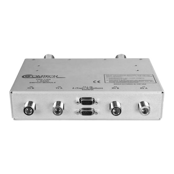
Chapter 5. CONNECTOR PINOUTS Overview The CRS-170A L-Band 1:1 Redundancy Switch connectors, shown in Figure 5-1, provide all necessary external connections between the switch module and the specified Comtech EF Data modem. J6 TX B J5 TX A J3 Control A... -
Page 118: Modem Side: Type 'N' If Connectors
Modem Side: Type ‘N’ IF Connectors Four 50Ω Type ‘N’ female connectors are provided on the modem side of the CRS-170A L-Band 1:1 Redundancy Switch module. Refer to Table 5-1 for details. Table 5-1. Modem Side Type ‘N’ Connectors Type ‘N’ Connector... -
Page 119: J3 Control Connector - Modem 'A' (Top), Db-9F
J3 Control Connector – Modem ‘A’ (Top), DB-9F The Modem ‘A’ Control connector is a 9-pin Type ‘D’ female interface located on the modem side of the CRS-170A L-Band 1:1 Redundancy Switch module. Refer to Table 5-2 for pin assignments. -
Page 120: J4 Control Connector - Modem 'B' (Bottom), Db-9F
J4 Control Connector – Modem ‘B’ (Bottom), DB-9F The Modem ‘B’ Control connector is a 9-pin Type ‘D’ female interface located on the modem side of the CRS-170A L-Band 1:1 Redundancy Switch module. Refer to Table 5-3 for pin assignments. -
Page 121: Antenna Side: Type 'N' If Connectors
MN/CRS170A.IOM Antenna Side: Type ‘N’ IF Connectors The 50Ω female Type ‘N’ connectors on the antenna side of the CRS-170A L-Band 1:1 Redundancy Switch module provide the coaxial cable connections to the outdoor receive and transmit equipment (BUC and LNB). - Page 122 CRS-170A L-Band 1:1 Redundancy Switch Revision 10 Connector Pinouts MN/CRS170A.IOM Notes: 5–6...
-
Page 123: Appendix A. Cable Drawings
Introduction This appendix contains drawings of cables used with the CRS-170A L-Band 1:1 Redundancy Switch. These cables are broken into two categories: Control Interface Cables and IF / Data Interface Cables. Each section provides illustrations of the cables’ technical specifications;... -
Page 124: Control Interface Cables
CRS-170A L-Band 1:1 Redundancy Switch Revision 10 Appendix A MN/CRS170A.IOM Control Interface Cables App. A CABLE CEFD REF Ch. 4 DESCRIPTION USED FOR (TYPE) USED WITH CRS-170A CDM-625/A CDM-840 4-16 CA/WR9378-4 Universal Cable, Control DB-9M DB-9M, 4’ 1:1 Control... -
Page 125: Universal Control Cable, Db-9M Db-9M
CRS-170A L-Band 1:1 Redundancy Switch Revision 10 Appendix A MN/CRS170A.IOM A.2.1 Universal Control Cable, DB-9M DB-9M Figure A-1. Universal Control Cable (CEFD P/N CA/WR9378-4) -
Page 126: Adapter Control Cable, Rohs, Db-9M Db-15F
CRS-170A L-Band 1:1 Redundancy Switch Revision 10 Appendix A MN/CRS170A.IOM A.2.2 Adapter Control Cable, RoHS, DB-9M DB-15F Figure A-2. Adapter Control Cable (CEFD P/N CA/WR12135-1) -
Page 127: Optional 'Y' Splitter Adapter Control Cable, (2X) Db-9M Db-15F
CRS-170A L-Band 1:1 Redundancy Switch Revision 10 Appendix A MN/CRS170A.IOM A.2.3 Optional ‘Y’ Splitter Adapter Control Cable, (2X) DB-9M DB-15F The optional CA/WR13011-4 ‘Y’ Splitter Adapter Control Cable, sold separately, is used in replacement of the CA/WA12135-1 cable. This cable permits user access to the Summary Fault Relay. -
Page 128: Optional Control Cable, Non-Muting, Db-9M Db-15F
CRS-170A L-Band 1:1 Redundancy Switch Revision 10 Appendix A MN/CRS170A.IOM A.2.4 Optional Control Cable, Non-muting, DB-9M DB-15F The optional CA-0000187 Control Cable, sold separately, is used in replacement of the CA/WA12135-1 cable. This cable keeps the offline modem’s Tx IF-enabled. -
Page 129: Data / Control 'Y' Cable, Modem To Crs-170A And Crs-150, Db-25M Db-25M
CRS-170A L-Band 1:1 Redundancy Switch Revision 10 Appendix A MN/CRS170A.IOM A.2.5 Data / Control ‘Y’ Cable, Modem to CRS-170A and CRS-150, DB-25M DB-25M, DB-9M Figure A-5. Data / Control ‘Y’ Cable (CEFD P/N CA/WR10456-4) -
Page 130: Control Cable, Modem To Crs-170A And Sms-301, Db-9M Db-15M
CRS-170A L-Band 1:1 Redundancy Switch Revision 10 Appendix A MN/CRS170A.IOM A.2.6 Control Cable, Modem to CRS-170A and SMS-301, DB-9M DB-15M Figure A-6. Control Cable (CEFD P/N CA/WR10163-1) - Page 131 CRS-170A L-Band 1:1 Redundancy Switch Revision 10 Appendix A MN/CRS170A.IOM This page is intentionally blank.
-
Page 132: If / Data Interface Cables
CRS-170A L-Band 1:1 Redundancy Switch Revision 10 Appendix A MN/CRS170A.IOM IF / Data Interface Cables App. A REF Ch. 4 CABLE CEFD P/N DESCRIPTION USED FOR (TYPE) USED WITH CRS-170A CDM-625/A CDM-625/A CDM-840 4-17 CDM-750/CDM-760 4-20 CDM-570L 4-26 CA/RF10453-4 RoHS Coax Cable, Type ‘N’... - Page 133 CRS-170A L-Band 1:1 Redundancy Switch Revision 10 Appendix A MN/CRS170A.IOM App. A REF Ch. 4 CABLE CEFD P/N DESCRIPTION USED FOR (TYPE) USED WITH CRS-170A Quad E1 Data Interface CDM-625/A A-10 CA-0000071 1:1 ‘Y’ Splitter Cable, (2X) DB-9M DB-9F, 8”...
-
Page 134: Modem To Crs-170A, L-Band Coaxial Cable, Rohs, Type 'N' 50Ω
CRS-170A L-Band 1:1 Redundancy Switch Revision 10 Appendix A MN/CRS170A.IOM A.3.1 Modem to CRS-170A, L-Band Coaxial Cable, RoHS, Type ‘N’ 50Ω Figure A-7. Tx/Rx 50Ω Type ‘N’ Coaxial Cable (CEFD P/N CA/RF10453-4) A-12... -
Page 135: Modem To Crs-170A Or User, 70/140 Mhz Coaxial Cable, Rohs, Type 'Bnc' 75Ω
CRS-170A L-Band 1:1 Redundancy Switch Revision 10 Appendix A MN/CRS170A.IOM A.3.2 Modem to CRS-170A or User, 70/140 MHz Coaxial Cable, RoHS, Type ‘BNC’ 75Ω Figure A-8. Tx/Rx/User Data 75Ω Type ‘BNC’ Coaxial Cable (CEFD P/N CA/BNC75OHM) A-13... -
Page 136: Modem To User, Splitter Cable, (2X) Db-25M Db-25F
CRS-170A L-Band 1:1 Redundancy Switch Revision 10 Appendix A MN/CRS170A.IOM A.3.3 Modem to User, Splitter Cable, (2X) DB-25M DB-25F Figure A-9. 1:1 User Data Splitter Cable (CEFD P/N CA/RB10461-1) A-14... -
Page 137: Modem To User, Cdm-625/A Data 'Y' Splitter Cable, (2X) Db-9M Db-9F
CRS-170A L-Band 1:1 Redundancy Switch Revision 10 Appendix A MN/CRS170A.IOM A.3.4 Modem to User, CDM-625/A Data ‘Y’ Splitter Cable, (2X) DB-9M DB-9F Figure A-10. 1:1 User Data ‘Y’ Splitter Cable (CEFD P/N CA-0000071) A-15... -
Page 138: Modem To User, Quad E1 'Y' Splitter Adapter Cable, (2X) Db-15F Db-9M
Modem to User, Quad E1 ‘Y’ Splitter Adapter Cable, (2X) DB-15F DB-9M This optional adapter cable may be purchased from Comtech EF Data to adapt the Balanced G.703 or Auxiliary G.703 DB-9F modem connections to a DB-15F connector pair. The DB-9M end of this cable plugs into the ‘To User’ connector side (DB-9F) of the CA-0000071 ‘Y’... -
Page 139: Modem To User, Quad E1 'Y' Splitter Adapter Cable, (2X) Rj-48F Db-9M
Modem to User, Quad E1 ‘Y’ Splitter Adapter Cable, (2X) RJ-48F DB-9M This optional adapter cable may be purchased from Comtech EF Data to adapt the Balanced G.703 or Auxiliary G.703 DB-9F modem connections to a RJ-48F connector pair. The DB-9M end of this cable plugs into the ‘To User’ connector side (DB-9F) of the CA-0000071 ‘Y’... -
Page 140: Modem To User, Quad E1 'Y' Splitter Adapter Cable Kit (Kt-0000122
CRS-170A L-Band 1:1 Redundancy Switch Revision 10 Appendix A MN/CRS170A.IOM A.3.7 Modem to User, Quad E1 ‘Y’ Splitter Adapter Cable Kit (KT-0000122) KT-0000122 Quad E1 Balanced/Unbalanced Adapter Kit CEFD P/N DESCRIPTION CA-0000347 ‘Y’ Cable Assy: DB-9M 2X RJ-48 Male 502-0532-001 Bolun Adapter, 2X RJ-48 Female ... -
Page 141: Modem To User, Overhead User Data 'Y' Splitter Cable, (2X) Hd-44M Hd-44F
CRS-170A L-Band 1:1 Redundancy Switch Revision 10 Appendix A MN/CRS170A.IOM A.3.8 Modem to User, Overhead User Data ‘Y’ Splitter Cable, (2X) HD-44M HD-44F Figure A-14. Overhead User Data ‘Y’ Splitter Cable (CEFD P/N CA-0000070) A-19... -
Page 142: Modem To Modem Shielded Multi-Drop Cnc Plus, Cdm-625/A 1:1 Cable, Db-9M Db-9M
CRS-170A L-Band 1:1 Redundancy Switch Revision 10 Appendix A MN/CRS170A.IOM ® A.3.9 Modem to Modem Shielded Multi-drop CnC Plus, CDM-625/A 1:1 Cable, DB-9M DB-9M ® Figure A-15. Modem to Modem Shielded Multi-drop CnC Plus, CDM-625/A 1:1 Cable (CEFD P/N CA-0000276) -
Page 143: Modem To User, Optical Gigabit Ethernet Single-Mode Or Multi-Mode Cable Assemblies, (2X) Type 'Lc' (4X) Type 'Lc
CRS-170A L-Band 1:1 Redundancy Switch Revision 10 Appendix A MN/CRS170A.IOM A.3.10 Modem to User, Optical Gigabit Ethernet Single-Mode OR Multi-Mode Cable Assemblies, (2X) Type ‘LC’ (4X) Type ‘LC’ Figure A-16. Optical Gigabit Ethernet User Data Cable Assembly (See Table for CEFD P/N) -
Page 144: Modem To User, G.703 Balanced User Data 'Y' Splitter Cable, (2X) Db-15M Db-15M
CRS-170A L-Band 1:1 Redundancy Switch Revision 10 Appendix A MN/CRS170A.IOM A.3.11 Modem to User, G.703 Balanced User Data ‘Y’ Splitter Cable, (2X) DB-15M DB-15M Figure A-17. G.703 Balanced User Data ‘Y’ Splitter Cable (CEFD P/N CA/WR10522-1) A-22... -
Page 145: Modem To User, Hssi User Data 'Y' Splitter Cable, (2X) Hd-50M Hd-50F
CRS-170A L-Band 1:1 Redundancy Switch Revision 10 Appendix A MN/CRS170A.IOM A.3.12 Modem to User, HSSI User Data ‘Y’ Splitter Cable, (2X) HD-50M HD-50F Figure A-18. HSSI User Data ‘Y’ Splitter Cable (CEFD P/N PP/SC3523) A-23... -
Page 146: Modem To User, Oc-3 Single-Mode Or Multi-Mode Cable Assemblies, Type 'Sc/Upc' (2X) Type 'Sc/Upc
CRS-170A L-Band 1:1 Redundancy Switch Revision 10 Appendix A MN/CRS170A.IOM A.3.13 Modem to User, OC-3 Single-Mode OR Multi-Mode Cable Assemblies, Type ‘SC/UPC’ (2X) Type ‘SC/UPC’ CEFD P/N Description Comments ‘Y’ Cable Assy – RoHS-Compliant, Optical Coupler (Single- or Multi-Mode), 7’, Type For CDM-700 Single-Mode OC-3 Interface;... - Page 148 2114 85281 WEST TH STREET TEMPE ARIZONA 480 • 333 • 2200 PHONE 480 • 333 • 2161...
Need help?
Do you have a question about the CRS-170A and is the answer not in the manual?
Questions and answers