
Subscribe to Our Youtube Channel
Related Manuals for KROHNE OPTIWAVE 5200 C/F


Summary of Contents for KROHNE OPTIWAVE 5200 C/F
- Page 1 OPTIWAVE 5200 C/F Handbook Non-contact Radar (FMCW) Level Meter for distance, level and volume measurement of liquids, pastes and slurries © KROHNE 03/2012 - 4001904901 - HB OPTIWAVE 5200 R01 en...
- Page 2 All rights reserved. It is prohibited to reproduce this documentation, or any part thereof, without the prior written authorisation of KROHNE Messtechnik GmbH. Subject to change without notice. Copyright 2012 by KROHNE Messtechnik GmbH - Ludwig-Krohne-Str. 5 - 47058 Duisburg (Germany) www.krohne.com 03/2012 - 4001904901 - HB OPTIWAVE 5200 R01 en...
-
Page 3: Table Of Contents
CONTENTS OPTIWAVE 5200 C/F 1 Safety instructions 1.1 Software history ....................... 6 1.2 Intended use ........................6 1.3 Certification ........................6 1.4 Radio approvals ........................ 7 1.4.1 European Union (EU)....................... 7 1.4.2 U.S.A. and Canada........................8 1.5 Safety instructions from the manufacturer ..............8 1.5.1 Copyright and data protection .................... - Page 4 CONTENTS OPTIWAVE 5200 C/F 4.3 Remote device version ....................36 4.3.1 General notes ........................36 4.3.2 Electrical installation: remote version ................. 36 4.3.3 Requirements for communication cables supplied by the customer........36 4.3.4 How to prepare a communication cable supplied by the customer ........38 4.3.5 How to connect the communication cable to the device ............
- Page 5 CONTENTS OPTIWAVE 5200 C/F 7.3 Spare parts availability ....................76 7.4 Availability of services ....................76 7.5 Returning the device to the manufacturer..............77 7.5.1 General information ......................77 7.5.2 Form (for copying) to accompany a returned device............78 7.6 Disposal .......................... 78 8 Technical data 8.1 Measuring principle......................
-
Page 6: Safety Instructions
SAFETY INSTRUCTIONS OPTIWAVE 5200 C/F 1.1 Software history Introduction Signal converter Mth./year Hardware Firmware Test version for field tests 03/2012 OPTIWAVE 5200 x.xx Series version 03/2012 OPTIWAVE 5200 x.xx 1.2 Intended use CAUTION! Responsibility for the use of the measuring devices with regard to suitability, intended use and corrosion resistance of the used materials against the measured fluid lies solely with the operator. -
Page 7: Radio Approvals
SAFETY INSTRUCTIONS OPTIWAVE 5200 C/F 1.4 Radio approvals 1.4.1 European Union (EU) LEGAL NOTICE! This level transmitter is intended for installation in closed tanks. It meets the requirements of the R & TTE (Radio Equipment and Telecommunications Terminal Equipment) Directive 1999/05/EC for use in the member countries of the EU. -
Page 8: And Canada
SAFETY INSTRUCTIONS OPTIWAVE 5200 C/F 1.4.2 U.S.A. and Canada LEGAL NOTICE! This device complies with Part 15 of the FCC Rules and with RSS-210 of Industry Canada. Operation is subject to the following two conditions: 1. This device may not cause harmful interference, and 2. -
Page 9: Disclaimer
SAFETY INSTRUCTIONS OPTIWAVE 5200 C/F 1.5.2 Disclaimer The manufacturer will not be liable for any damage of any kind by using its product, including, but not limited to direct, indirect or incidental and consequential damages. This disclaimer does not apply in case the manufacturer has acted on purpose or with gross negligence. In the event any applicable law does not allow such limitations on implied warranties or the exclusion of limitation of certain damages, you may, if such law applies to you, not be subject to some or all of the above disclaimer, exclusions or limitations. -
Page 10: Warnings And Symbols Used
SAFETY INSTRUCTIONS OPTIWAVE 5200 C/F 1.5.5 Warnings and symbols used Safety warnings are indicated by the following symbols. DANGER! This information refers to the immediate danger when working with electricity. DANGER! This warning refers to the immediate danger of burns caused by heat or hot surfaces. -
Page 11: Device Description
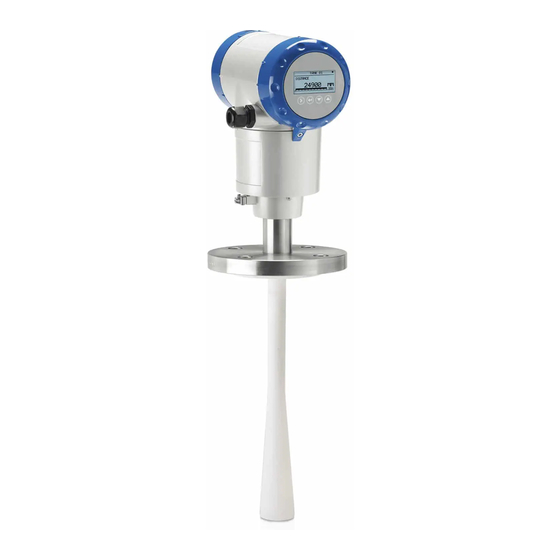
DEVICE DESCRIPTION OPTIWAVE 5200 C/F 2.2 Device description The FMCW radar level transmitter is designed to measure the distance, level, mass, volume and reflectivity of liquids, pastes and slurries. Radar level transmitters use an antenna to guide a signal to the surface of the measured product. Radar is a non-contact technology. -
Page 12: Device Description
DEVICE DESCRIPTION OPTIWAVE 5200 C/F The converter can be ordered with horizontal or vertical housing options for easy access to the device terminals and the optional display. Figure 2-4: Antenna options 1 PP Wave Horn antenna 2 PTFE Wave Horn antenna 3 Metallic Horn antenna (available sizes: DN80, DN100, DN150 and DN200) 4 Wave Guide antenna (Length options: 1...6 m / 3.28...19.68 ft, in increments of 0.5 m / 1.64 ft) -
Page 13: Installation
INSTALLATION OPTIWAVE 5200 C/F 3.5 Installation 3.5.1 Pressure and temperature ranges Figure 3-2: Pressure and temperature ranges 1 Flange temperature Non-Ex devices: Depends on the type of antenna, process connection and the seal material. Refer to the table that fol- lows. -
Page 14: Installation
INSTALLATION OPTIWAVE 5200 C/F Figure 3-3: Ambient temperature / flange temperature, flange and threaded connection, in °C Figure 3-4: Ambient temperature / flange temperature, flange and threaded connection, in °F 1 Maximum ambient temperature, °C 2 Maximum flange temperature, °C 3 Maximum ambient temperature, °F... -
Page 15: Mounting Position (Theoretical Data For Nozzle Position)
INSTALLATION OPTIWAVE 5200 C/F 3.5.2 Mounting position (theoretical data for nozzle position) CAUTION! Follow these recommendations to make sure that the device measures correctly. Figure 3-5: Recommended mounting position for liquids, pastes and slurries 1 Sockets for the PP Wave Horn antenna... - Page 16 INSTALLATION OPTIWAVE 5200 C/F Figure 3-6: Product inlets 1 The device is in the correct position. 2 The device is too near to the product inlet. Point the device in the correct direction Figure 3-7: Point the device in the correct direction to get the best performance Point the tag hole on the housing in the direction of the nearest tank wall.
- Page 17 INSTALLATION OPTIWAVE 5200 C/F Figure 3-9: Tanks with tapered (conical etc.) bottoms Tapered (conical etc.) bottoms have an effect on the measuring range. The device cannot measure to the bottom of the tank. 1 Radar beam 2 Minimum level reading 03/2012 - 4001904901 - HB OPTIWAVE 5200 R01 en www.krohne.com...
-
Page 18: Mounting Restrictions
INSTALLATION OPTIWAVE 5200 C/F 3.5.3 Mounting restrictions CAUTION! Follow these recommendations to make sure that the device measures correctly. We recommend that you prepare the installation when the tank is empty. Mounting restrictions: General data Figure 3-10: Mounting restrictions: General data 1 Do not tilt the device more than 2°... - Page 19 INSTALLATION OPTIWAVE 5200 C/F Obstacles in the tank Figure 3-11: Obstacles in the tank Do not put the device directly above obstacles (agitator, support beams, heating tubes etc.). Parasitic signals from obsta- cles will cause the device to measure incorrectly.
- Page 20 INSTALLATION OPTIWAVE 5200 C/F Devices with plastic Wave Horn antenna (PTFE, PP) Figure 3-13: Devices with plastic Wave Horn antenna a ≤ 44 mm / 1.7¨; b ≤ 40 mm / 1.6¨ 1 Device with a PTFE Wave Horn antenna and a flange connection...
- Page 21 INSTALLATION OPTIWAVE 5200 C/F Requirements for flange connections Figure 3-15: Flange connection Equipment needed: • Device • Flange gasket (not supplied) • Wrench (not supplied) • Make sure the flange on the nozzle is level. • Make sure that you use the applicable gasket for the flange dimensions and the process.
-
Page 22: Standpipes (Stilling Wells And Bypass Chambers)
INSTALLATION OPTIWAVE 5200 C/F • Make sure that you point the device in the correct direction. Refer to "Point the device in the correct direction" in this section. • Tighten the connection. Refer to local rules and regulations for the correct torque to apply to the connection. - Page 23 INSTALLATION OPTIWAVE 5200 C/F CAUTION! Installation requirements The standpipe must be electrically conductive. • The inside diameter of the standpipe must not be more than 5 mm / 0.2 over the diameter of the antenna (for a high-dielectric • ¨...
- Page 24 INSTALLATION OPTIWAVE 5200 C/F Stilling wells: floating roofs If the device must be installed on a tank with a floating roof, install it in a stilling well. Figure 3-18: Floating roofs 1 Sediment 2 Support fixtures 3 Stilling well 4 Floating roof...
- Page 25 INSTALLATION OPTIWAVE 5200 C/F Figure 3-19: Horizontal cylindrical tanks 1 The device is installed without a stilling well. There are multiple reflections. Refer to the CAUTION! that follows. 2 The device is installed in a stilling well and measures correctly.
-
Page 26: How To Turn Or Remove The Signal Converter
INSTALLATION OPTIWAVE 5200 C/F • Additional process connections are necessary for the liquids to circulate freely along the length of the bypass chamber. 3.5.5 How to turn or remove the signal converter INFORMATION! The converter turns 360 ° Figure 3-20: How to turn or remove the signal converter... -
Page 27: How To Open The Weather Protection
INSTALLATION OPTIWAVE 5200 C/F 3.5.6 How to open the weather protection Figure 3-21: How to open the weather protection 1 Loosen the bolt on each side of the weather protection. 2 Pull the sides of the weather protection out of the notch for the closed position. -
Page 28: Electrical Connections
ELECTRICAL CONNECTIONS OPTIWAVE 5200 C/F 4.1 Safety instructions DANGER! All work on the electrical connections may only be carried out with the power disconnected. Take note of the voltage data on the nameplate! DANGER! Observe the national regulations for electrical installations! DANGER! For devices used in hazardous areas, additional safety notes apply;... - Page 29 ELECTRICAL CONNECTIONS OPTIWAVE 5200 C/F Figure 4-2: How to open the terminal compartment cover • Turn the cover counterclockwise with a strap wrench. • Remove the cover. Figure 4-3: Procedure for electrical installation Equipment needed: • Small slotted tip screwdriver (not supplied) CAUTION! Make sure that the polarity of the wires is correct.
-
Page 30: Non-Ex Devices
ELECTRICAL CONNECTIONS OPTIWAVE 5200 C/F Figure 4-4: How to close the terminal compartment cover • Attach the cover. • Turn the cover clockwise. 4.2.1 Non-Ex devices Figure 4-5: Electrical connections for non-Ex devices 1 Power supply 2 Resistor for HART communication ®... -
Page 31: Remote Device Version
ELECTRICAL CONNECTIONS OPTIWAVE 5200 C/F 4.3 Remote device version 4.3.1 General notes To be defined. 4.3.2 Electrical installation: remote version Figure 4-6: Terminals for electrical installation 1 Grounding terminal in the housing (if the device is grounded) 2 Current output -... - Page 32 ELECTRICAL CONNECTIONS OPTIWAVE 5200 C/F Maximum length of the communication cable • Non-Ex applications: 100 m / 328 ft • Ex applications: refer to the supplementary operating instructions or approval certificates. Use the Ex-approved cable supplied with the device! Temperature •...
-
Page 33: How To Prepare A Communication Cable Supplied By The Customer
ELECTRICAL CONNECTIONS OPTIWAVE 5200 C/F 4.3.4 How to prepare a communication cable supplied by the customer Figure 4-7: Equipment needed to prepare the communication cable 1 Communication cable (supplied on request) 2 2 heat-shrinkable sleeves for the PVC jacket (not supplied) -
Page 34: How To Connect The Communication Cable To The Device
ELECTRICAL CONNECTIONS OPTIWAVE 5200 C/F Figure 4-8: How to prepare the communication cable a = 50 mm / 2¨ 1 Remove the PVC jacket from the wire to dimension "a". 2 Remove the insulation from the wire. Obey national regulations for electrical wiring. - Page 35 ELECTRICAL CONNECTIONS OPTIWAVE 5200 C/F Equipment needed Figure 4-9: Equipment needed to prepare the communication cable 1 Remote coverter 2 Antenna housing How to prepare a communi- cation cable supplied by the customer 3 Communication cable (supplied on request for non-Ex devices) - for more data, refer to...
- Page 36 ELECTRICAL CONNECTIONS OPTIWAVE 5200 C/F How to connect the communication cable to the remote converter Figure 4-11: How to connect the communication cable to the remote converter CAUTION! Bending radius of the communication cable: ≥ 50 mm / 2 ¨...
- Page 37 ELECTRICAL CONNECTIONS OPTIWAVE 5200 C/F How to connect the communication cable to the antenna housing Figure 4-12: How to connect the communication cable to the antenna housing CAUTION! Bending radius of the communication cable: ≥ 50 mm / 2 ¨...
-
Page 38: Protection Category
ELECTRICAL CONNECTIONS OPTIWAVE 5200 C/F 4.4 Protection category INFORMATION! The device fulfills all requirements per protection category IP 66/67 (equivalent to NEMA type 4X (housing) and type 6P (antenna)). DANGER! Make sure that the cable gland is watertight. Figure 4-13: How to make the installation agree with protection category IP 67 •... -
Page 39: Networks
ELECTRICAL CONNECTIONS OPTIWAVE 5200 C/F 4.5 Networks 4.5.1 General information The device uses the HART communication protocol. This protocol agrees with the HART Communication Foundation standard. The ® ® device can be connected point-to-point. It can also operate in a multi-drop network of up to 15 devices. -
Page 40: Multi-Drop Networks
ELECTRICAL CONNECTIONS OPTIWAVE 5200 C/F 4.5.3 Multi-drop networks Figure 4-15: Multi-drop network (non-Ex) 1 Address of the device (n+1 for multidrop networks) 2 Address of the device (1 for multidrop networks) 3 4 mA + HART ® 4 Resistor for HART communication ®... -
Page 41: Fieldbus Networks
ELECTRICAL CONNECTIONS OPTIWAVE 5200 C/F 4.5.4 Fieldbus networks FOUNDATION Fieldbus™ network (non-Ex) Figure 4-16: FOUNDATION Fieldbus™ network (non-Ex) 1 Field device 2 Junction box 3 H1 network 4 H1/HSE converter 5 High Speed Ethernet (HSE) 6 Workstation INFORMATION! It is necessary to have a separate power supply to energize devices with the FOUNDATION ™... - Page 42 ELECTRICAL CONNECTIONS OPTIWAVE 5200 C/F PROFIBUS PA/DP network (non-Ex) Figure 4-17: PROFIBUS PA/DP network (non-Ex) 1 Field device 2 Bus termination 3 PROFIBUS PA bus segment 4 Segment coupler (PA/DP link) 5 PROFIBUS DP bus line 6 Control system (PLC / Class 1 master device)
-
Page 43: Start-Up
START-UP OPTIWAVE 5200 C/F 5.1 How to start the device 5.1.1 Start-up checklist Check these points before you energize the device: • Are all the wetted components (antenna, flange and gaskets) resistant to the product in the tank? • Does the information on the signal converter nameplate agree with the operating data? •... -
Page 44: Digital Display Screen
START-UP OPTIWAVE 5200 C/F 5.3 Digital display screen 5.3.1 Local display screen layout Figure 5-1: Local display screen layout in Normal mode 1 Current output percentage (bar graph and text - only shown if the current output function is the same as the measure- ment on the screen in normal mode) -
Page 45: Keypad Buttons
OPERATION OPTIWAVE 5200 C/F Figure 5-2: Local display screen layout in configuration mode 1 Function name 2 Configuration mode symbol 3 Menu number 5.3.2 Keypad buttons Keypad button Function Readings: Enter Commissioning menu (Enter Configuration mode) [Right] Readings: Change units (m, cm, mm, in, ft) Configuration... -
Page 46: Operation
OPERATION OPTIWAVE 5200 C/F 6.1 User modes Normal mode Normal mode This mode displays measurement data. For more data, refer to on page 52. Configuration mode Use this mode to view parameters, commission the device, create tables for volume or mass measurement, change critical values to measure in difficult process conditions. -
Page 47: Configuration Mode
OPERATION OPTIWAVE 5200 C/F Measurement type definitions Measurement type Description Available units LEVEL This is a display and an output function option. It is m, cm, mm, in (inches), ft the height from the bottom of the tank to the surface (feet) of the liquid (Tank height - Distance). -
Page 48: How To Get Access To The Commissioning Menu
OPERATION OPTIWAVE 5200 C/F 6.3.2 How to get access to the commissioning menu Do the steps that follow: • Press the [>] button. This shows the Information menu. The Information menu is read only and does not have password security. -
Page 49: Keypad Functions
OPERATION OPTIWAVE 5200 C/F 6.3.3 Keypad functions Figure 6-1: Local display screen layout in configuration mode 1 Function name 2 Configuration mode symbol 3 Menu number This is what you see when you are in Configuration mode. The functions of the buttons are given in the table that follows:... - Page 50 OPERATION OPTIWAVE 5200 C/F Lists of parameters in menu items Figure 6-2: Lists of parameters in menu items 1 Parameter 2 Menu name This is what you see when you select a menu item that has a list of parameters. The functions of the buttons are given in the table that...
- Page 51 OPERATION OPTIWAVE 5200 C/F Values in menu items Figure 6-3: Values in menu items 1 Menu item with values stored at this time (first screen) 2 Press [>] again to change the values. A cursor shows on the first digit.
-
Page 52: Function Description
OPERATION OPTIWAVE 5200 C/F 6.3.4 Menu overview 1.0.0 Info. (Information) 1.1.0 Ident. (Identification) 1.2.0 Output 1.3.0 History 2.0.0 Supervisor 2.1.0 Commissioning 2.2.0 Tests 2.3.0 Basic Parameters 2.4.0 Output I 2.5.0 Application 2.6.0 Communication 2.7.0 Display 2.8.0 Conversion 2.9.0 Config/Reset 3.0.0 Service Password locked. - Page 53 OPERATION OPTIWAVE 5200 C/F Menu Function Function description Selection list Default 1.3.0 HISTORY 1.3.1 ERROR RECORD A log of device errors. Press [>] to read the Read only. errors. Press [ ] or [ ] to scroll up or down the list.
- Page 54 OPERATION OPTIWAVE 5200 C/F Menu Function Function description Selection list Default Emp.Spec.Type Maximum, Average Use the average value for tanks which contain fixed objects only. Use the maximum value for tanks which contain many objects or moving objects. Recording in progress...
- Page 55 OPERATION OPTIWAVE 5200 C/F Menu Function Function description Selection list Default 2.3.4 STILLWELL EN. If the device is installed in a stilling well YES, NO or has a Wave- Guide antenna, set this menu item to "Yes". 2.3.5 STILLWELL D.
- Page 56 OPERATION OPTIWAVE 5200 C/F Menu Function Function description Selection list Default 2.4.2 RANGE I This parameter sets the range of the 4-20, 4-20/22E, 4-20/3.6E, 4-20/3.6E output current with (3.8...20.5 mA) or 3.8-20.5/22E, 3.8-20.5/3.6E without (4...20 mA) over-run values. It also tells the device what to do if an error occurs.
- Page 57 OPERATION OPTIWAVE 5200 C/F Menu Function Function description Selection list Default 2.5.4 MEASUR.MODE The device uses the dielectric constant (ε Direct, TBF Partial, TBF Full Direct of the tank contents to monitor level. In direct mode (if the dielectric constant is high), the level signal is a reflection on the surface of the tank contents.
- Page 58 OPERATION OPTIWAVE 5200 C/F Menu Function Function description Selection list Default 2.7.2 LENGTH UNIT The length unit shown in normal m, cm, mm, in (inches), ft mode. (feet) Conversion unit. The length, volume, mass m3, L, gal (US gallons), ImpG 2.7.3...
- Page 59 TECHNICAL DATA OPTIWAVE 5200 C/F 3. Service menu Menu Function Function description Selection list Default Advanced settings. The settings in this menu 3.0.0 SERVICE are protected with a password. Only approved personnel can change the parameters in this menu. For more data, contact your local sales office.
- Page 60 TECHNICAL DATA OPTIWAVE 5200 C/F 5 Differential time delay, Δt 6 Differential frequency, Δf 7 Frequency transmitted 8 Frequency received 9 Frequency 10 Time www.krohne.com 03/2012 - 4001904901 - HB OPTIWAVE 5200 R01 en...
- Page 61 TECHNICAL DATA OPTIWAVE 5200 C/F Measurement modes "Direct" mode If the dielectric constant of the tank contents is high (ε >1.8), the level signal is a reflection on the surface of the tank contents. "Full TBF" mode TBF = Tank Bottom Following. If the dielectric constant of the tank contents is very low (ε...
-
Page 62: Level Measurement
TECHNICAL DATA OPTIWAVE 5200 C/F 8.2 Technical data INFORMATION! The following data is provided for general applications. If you require data that is more • relevant to your specific application, please contact us or your local representative. Additional information (certificates, special tools, software,...) and complete product documentation can be downloaded free •... -
Page 63: Technical Data
TECHNICAL DATA OPTIWAVE 5200 C/F Display and user interface Display LCD display 128 × 64 pixels in 8-step greyscale with 4-button keypad Interface languages 3 language pack options (the language is given the customer order): 1 English, French German and Italian... -
Page 64: Technical Data
TECHNICAL DATA OPTIWAVE 5200 C/F Installation conditions Process connection size The nominal diameter (DN) should be equal to or larger than the antenna diameter. Process connection position Make sure that there are not any obstructions directly below the process connection for the device. - Page 65 TECHNICAL DATA OPTIWAVE 5200 C/F Cable gland Standard: none Options: M20×1.5 (cable diameter: 6...10 mm / 0.23...0.39¨); others are available on request Cable entry capacity (terminal) 0.5…1.5 mm² Input and output Output signal 4…20 mA HART or 3.8…20.5 mA acc. to NAMUR NE 43 ®...
- Page 66 TECHNICAL DATA OPTIWAVE 5200 C/F Other standards and approvals SIL 2 (the requirements for functional safety agree with IEC 61508 (2010)) Electromagnetic Compatibility Directive 2004/108/EC in conjunction with EN 61326-1 (2006) SIL 2-approved devices agree with EN 61326-3-1 (2006) and EN 61326-3-2 (2006) Radio Equipment and Telecommunications Terminal Equipment Directive R &...
Need help?
Do you have a question about the OPTIWAVE 5200 C/F and is the answer not in the manual?
Questions and answers