
Related Manuals for KROHNE BATCHFLUX 5500 C


Summary of Contents for KROHNE BATCHFLUX 5500 C
- Page 1 BATCHFLUX 5500 C BATCHFLUX 5500 C BATCHFLUX 5500 C BATCHFLUX 5500 C Quick Start Quick Start Quick Start Quick Start Electromagnetic flowmeter for volumetric filling machines © KROHNE 05/2014 - 4003386301 - QS BATCHFLUX 5500 R03 en...
-
Page 2: Table Of Contents
CONTENTS BATCHFLUX 5500 C 1 Safety instructions 2 Installation 2.1 Scope of delivery....................... 4 2.2 Device description ......................5 2.3 Nameplate ........................5 2.4 Storage ..........................6 2.5 Pre-installation requirements ..................6 2.6 General requirements ...................... 6 2.7 Installation conditions ...................... 8 2.7.1 Inlet and outlet ........................ -
Page 3: Safety Instructions
SAFETY INSTRUCTIONS BATCHFLUX 5500 C Warnings and symbols used DANGER! This information refers to the immediate danger when working with electricity. DANGER! These warnings must be observed without fail. Even partial disregard of this warning can lead to serious health problems and even death. There is also the risk of seriously damaging the device or parts of the operator's plant. -
Page 4: Installation
INSTALLATION BATCHFLUX 5500 C 2.1 Scope of delivery INFORMATION! Inspect the packaging carefully for damages or signs of rough handling. Report damage to the carrier and to the local office of the manufacturer. INFORMATION! Do a check of the packing list to make sure that you have all the elements given in the order. -
Page 5: Device Description
INSTALLATION BATCHFLUX 5500 C 2.2 Device description Your measuring device is supplied ready for operation. The factory settings for the operating data have been made in accordance with your order specifications. The following compact versions are available: • Version 1: converter directly mounted on cast sensor housing in size DN2.5..6 •... -
Page 6: Storage
INSTALLATION BATCHFLUX 5500 C 2.4 Storage • Store the device in a dry and dust-free location. • Avoid lasting direct exposure to the sun. • Store the device in its original packaging. • Storage temperature: -50 ...+70°C / -58...+158°F 2.5 Pre-installation requirements Make sure that you have all necessary tools available: •... - Page 7 INSTALLATION BATCHFLUX 5500 C Figure 2-4: Avoid vibrations Figure 2-5: Avoid strong magnetic fileds Figure 2-6: Horizontal piperun CAUTION! Install in a slightly descending pipe section to prevent air from collecting and to avoid faulty measurements (meter can drain). 05/2014 - 4003386301 - QS BATCHFLUX 5500 R03 en...
-
Page 8: Installation Conditions
INSTALLATION BATCHFLUX 5500 C 2.7 Installation conditions 2.7.1 Inlet and outlet Figure 2-7: Inlet and outlet section 1 ≥ 5 DN 2 ≥ 2 DN 3 Drain valve (to empty pipeline) 2.7.2 Control valve Figure 2-8: Installation before control valve 2.7.3 Pump... -
Page 9: Open Feed Or Discharge
INSTALLATION BATCHFLUX 5500 C 2.7.4 Open feed or discharge Figure 2-10: Installation before an open discharge 2.7.5 Mounting 2.7.6 Mounting position Figure 2-11: Installation in bending pipes ∠α ; > 2° 1. Drain valve ( to empty pipeline) CAUTION! Avoid draining or partial filling of the flow sensor. -
Page 10: Installation Location
INSTALLATION BATCHFLUX 5500 C 2.7.7 Installation location Figure 2-12: Installation location CAUTION! Mount the flow sensor in such a way that the electrode axis (X--------X) is approximately in a horizontal pipe run. 2.7.8 Flange deviation Figure 2-13: Mounting position and flange deviation CAUTION! Max. -
Page 11: Temperatures
INSTALLATION BATCHFLUX 5500 C 2.7.9 Temperatures Process temperature vs ambient temperature 1 Ambient temperature 2 Process temperature 2.7.10 Hot filling Installation position Figure 2-14: In case of hot fluids INFORMATION! Avoid installation near hot product tanks. If possible, try to insulate the flowmeter from radiant heat sources. -
Page 12: Electrical Connections
ELECTRICAL CONNECTIONS BATCHFLUX 5500 C 3.1 Safety instructions DANGER! All work on the electrical connections may only be carried out with the power disconnected. Take note of the voltage data on the nameplate! DANGER! Observe the national regulations for electrical installations! DANGER! For devices used in hazardous areas, additional safety notes apply;... -
Page 13: Electrical Connection
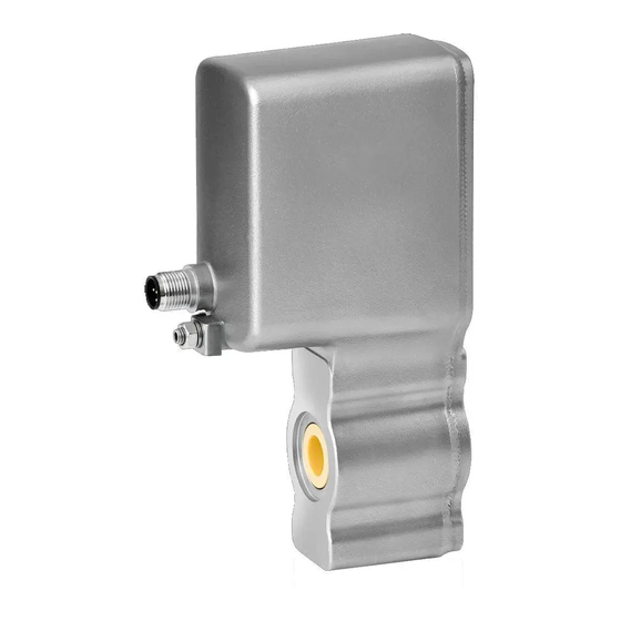
3.3 Electrical connection 3.3.1 Cable connector M12 - 5 pin All operating data for the BATCHFLUX 5500 C are preset at the factory. For changing the parameters and diagnostic purposes BATCHMon plus operation software can be used. 1 +24 VDC... -
Page 14: Cable Connector M12 - 8 Pin (With Status Output)
ELECTRICAL CONNECTIONS BATCHFLUX 5500 C 3.3.2 Cable connector M12 - 8 pin (with status output) The 8 pin electric connection has a status output. This status output, is configurable to customer specifications and offers either the flow direction (of the medium) or an error signal. -
Page 15: Technical Data
TECHNICAL DATA BATCHFLUX 5500 C 4.1 Dimensions and weights DN2.5...6 Figure 4-1: Dimensions 1 (Grounding) 2 M12; 5 - 8 pins connector Nominal Dimensions [mm] Weight size [kg] 6 → 2.5 DN2.5 7 → 3.2 9 → 4.8 Note on dimension d: As the diameter reduces to the middle, the diameter is specified for the inlet and... - Page 16 TECHNICAL DATA BATCHFLUX 5500 C DN10...15 1 (Grounding) 2 M12; 5 - 8 pins connector Nominal Dimensions [mm] Weight size [kg] 10.5 → 8 DN10 45.4 106.5 14 → 12 DN15 45.4 106.5 Note on dimension d: As the diameter reduces to the middle, the diameter is specified for the inlet and...
- Page 17 TECHNICAL DATA BATCHFLUX 5500 C DN25..40 Figure 4-2: Dimensions 1 (Grounding) 2 M12; 5 - 8 pins connector Nominal Dimensions [mm] Weight [kg] size 26 → 20 DN25 39 → 30 DN40 Note on dimension d: As the diameter reduces to the middle, the diameter is specified for the inlet and...
-
Page 18: Counter Flanges
The O-rings require periodic inspection and replacement. As the interval depends on process- specific variables, the length of the interval cannot be specified. The O-rings are not part of the portfolio of KROHNE. INFORMATION! For 3A applications, O-rings must conform to the requirements of the 3A sanitary standard for Flow meters, number 28-04 Class I or Class II (max. - Page 19 TECHNICAL DATA BATCHFLUX 5500 C Reference to specific dimensions and drawing numbers Size DN Pcd [mm] D [mm] W [mm] Drawing number Ø 56 Ø 68 14.5 4000587801 Ø 56 Ø 68 14.5 4000587807 Ø 56 Ø 68 14.5 4000587810 Ø...
- Page 20 Measuring systems for the marine industry Head Office KROHNE Messtechnik GmbH Ludwig-Krohne-Str. 5 47058 Duisburg (Germany) Tel.:+49 203 301 0 Fax:+49 203 301 103 89 info@krohne.com The current list of all KROHNE contacts and addresses can be found at: www.krohne.com...
Need help?
Do you have a question about the BATCHFLUX 5500 C and is the answer not in the manual?
Questions and answers