KROHNE OPTISWIRL 5080 Supplementary Instructions Manual
Vortex flowmeter for high temperature applications
Hide thumbs
Also See for OPTISWIRL 5080:
- Supplementary instructions manual (20 pages) ,
- Handbook (100 pages)
Table of Contents
Advertisement
Quick Links
OPTISWIRL 5080
OPTISWIRL 5080
OPTISWIRL 5080
OPTISWIRL 5080
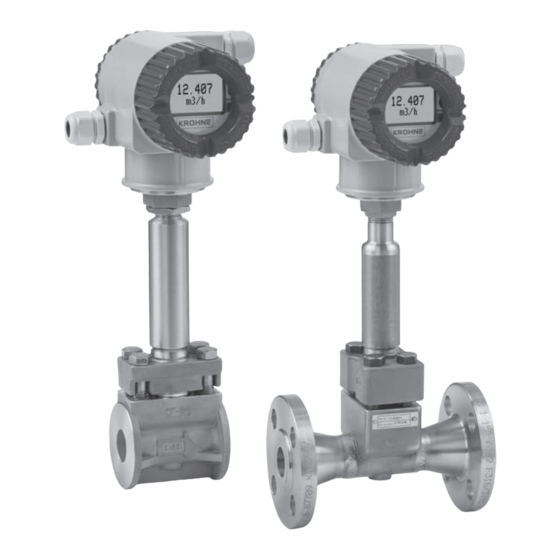
Vortex flowmeter for high temperature applications
Intrinsically safe version
ATEX category: II 1 G and II 2 D
ATEX category:
ATEX category:
ATEX category:
Equipment protection level: Ga and Db
Equipment protection level:
Equipment protection level:
Equipment protection level:
© KROHNE 04/2020 - 4007962401 - AD OPTISW5080 Exi Ga-Db en R01
Supplementary Instructions
Supplementary Instructions
Supplementary Instructions
Supplementary Instructions
Advertisement
Table of Contents

Related Manuals for KROHNE OPTISWIRL 5080


Summary of Contents for KROHNE OPTISWIRL 5080
- Page 1 ATEX category: II 1 G and II 2 D ATEX category: ATEX category: Equipment protection level: Equipment protection level: Equipment protection level: Equipment protection level: Ga and Db © KROHNE 04/2020 - 4007962401 - AD OPTISW5080 Exi Ga-Db en R01...
-
Page 2: Table Of Contents
CONTENTS OPTISWIRL 5080 1 Safety instructions 1.1 General notes ........................3 1.2 EU conformity ........................3 1.3 Approval according to the IECEx scheme ................ 4 1.4 Safety instructions......................4 2 Device description 2.1 Device description ......................5 2.2 Marking..........................5 2.3 Safety specifications...................... -
Page 3: Safety Instructions
SAFETY INSTRUCTIONS OPTISWIRL 5080 1.1 General notes These additional instructions apply to intrinsically safe versions of vortex flowmeters with following specifications: • ATEX category: II 1 G and II 2 D • Equipment protection level (EPL): Ga and Db • Ex marking: Ex ia IIC T4 Ga and Ex tb IIIC T103°C Db They complete the standard documentation for the non-explosion protected versions. -
Page 4: Approval According To The Iecex Scheme
SAFETY INSTRUCTIONS OPTISWIRL 5080 1.3 Approval according to the IECEx scheme Conformity of the vortex flowmeter for use in hazardous areas with gas and dust was tested in accordance with the "IECEx Certification Scheme for Explosive Atmospheres" according to IEC 60079-0:2011, IEC 60079-1:2014, IEC 60079-11:2011, IEC 60079-26:2004 and IEC 60079-31:2013. -
Page 5: Device Description
DEVICE DESCRIPTION OPTISWIRL 5080 2.1 Device description Vortex flowmeters measure and display the flow of flammable and non-flammable gases, steam and liquids. They transmit a 4...20 mA or digital multidrop, and a pulse output signal, as ® applicable, using HART communication protocol for remote configuration, calibration and monitoring. - Page 6 DEVICE DESCRIPTION OPTISWIRL 5080 Figure 2-2: Example of a nameplate for the remote version 1 Model number and serial number 2 Product designation 3 IP rating for enclosure 4 Warning for opening enclosure in hazardous areas 5 Note for disposal...
-
Page 7: Safety Specifications
DEVICE DESCRIPTION OPTISWIRL 5080 2.3 Safety specifications Type of protection Hazardous area classification Gas environment Gas environment Gas environment Gas environment Equipment protection by intrinsic safety: Equipment protection by intrinsic safety: Equipment protection by intrinsic safety: Equipment protection by intrinsic safety:... -
Page 8: Ambient Temperature / Temperature Classes
DEVICE DESCRIPTION OPTISWIRL 5080 2.5 Ambient temperature / temperature classes Because of the influence of the temperature of the product, no fixed temperature class is assigned to vortex flowmeters. The temperature class of these devices is rather a function of the product temperature and ambient temperature that is present and the specific device version. -
Page 9: Electrical Data
DEVICE DESCRIPTION OPTISWIRL 5080 2.6 Electrical data Signal circuits Signal circuits Signal circuits Signal circuits The vortex flowmeter signal circuits may only be connected to separate, certified, intrinsically safe isolating amplifiers or Zener barriers connected to separate, intrinsically safe circuits with... -
Page 10: Installation
INSTALLATION OPTISWIRL 5080 3.1 Mounting Installation and setup must be carried out according to the applicable installation standards (e.g. EN 60079-14) by qualified personnel trained in explosion protection. The information given in the manual and these instructions must always be observed. -
Page 11: Special Conditions
• As aluminium is used at the accessible surface of the signal converter housing, in the event of rare incidents, ignition sources due to impact and friction sparks could occur. This shall be considered when the OPTISWIRL 5080 vortex flowmeter is being installed in group IIC, zone 0 classified locations. -
Page 12: Electrical Connections
ELECTRICAL CONNECTIONS OPTISWIRL 5080 4.1 General notes The separate intrinsically safe signal circuits are electrically connected in the terminal compartment of the signal converter. The circuits are designed in type of protection "intrinsic safety" and galvanically not isolated from ground. -
Page 13: Outputs
ELECTRICAL CONNECTIONS OPTISWIRL 5080 4.3 Outputs The terminal assignment is described in the standard manual. The signal circuits of the vortex flowmeters must only be connected to certified intrinsically safe circuits. For more information refer to chapter "Electrical data". The 4...20 mA current output circuit and the pulse output circuit are galvanically isolated from each other. -
Page 14: Operation
OPERATION OPTISWIRL 5080 5.1 Start-up Start-up may only initiate when the vortex flowmeter: • is correctly installed in the system and connected. • has been checked for the proper state with regard to its installation and connection requirements. • has been correctly locked to the electronics and terminal compartment. -
Page 15: Service
SERVICE OPTISWIRL 5080 6.1 Maintenance Maintenance work of a safety-relevant nature within the meaning of explosion protection may only be carried out by the manufacturer, his authorised representative or under the supervision of authorised inspectors. Fluids containing abrasive particles and flowing at high rates can cause significant wear to pipes. - Page 16 SERVICE OPTISWIRL 5080 Exchanging the entire device The dismantling and installation is within the responsibility of the operator. Before disconnecting the electric connection cable of the device, make sure that all cables leading to the indication unit are isolated from the ground of the hazardous area.
-
Page 17: Notes
NOTES OPTISWIRL 5080 04/2020 - 4007962401 - AD OPTISW5080 Exi Ga-Db en R01 www.krohne.com... - Page 18 NOTES OPTISWIRL 5080 www.krohne.com 04/2020 - 4007962401 - AD OPTISW5080 Exi Ga-Db en R01...
- Page 19 NOTES OPTISWIRL 5080 04/2020 - 4007962401 - AD OPTISW5080 Exi Ga-Db en R01 www.krohne.com...
- Page 20 • Process Analysis • Services Head Office KROHNE Messtechnik GmbH Ludwig-Krohne-Str. 5 47058 Duisburg (Germany) Tel.: +49 203 301 0 Fax: +49 203 301 10389 info@krohne.com The current list of all KROHNE contacts and addresses can be found at: www.krohne.com...
Need help?
Do you have a question about the OPTISWIRL 5080 and is the answer not in the manual?
Questions and answers