KROHNE OPTIWAVE 5200 C Supplementary Instructions Manual
2-wire/10 ghz radar (fmcw) level meter
Hide thumbs
Also See for OPTIWAVE 5200 C:
- Quick start-up (40 pages) ,
- Supplementary instructions manual (32 pages) ,
- Supplementary instructions manual (32 pages)
Table of Contents
Advertisement
Quick Links
OPTIWAVE 5200 C
OPTIWAVE 5200 C
OPTIWAVE 5200 C
OPTIWAVE 5200 C
2-wire / 10 GHz Radar (FMCW) Level Meter
Safety manual
Safety manual
Safety manual
Safety manual
© KROHNE 02/2013 - 4001906202 - AD SIL OPTIWAVE 5200 R02 en
Supplementary instructions
Supplementary instructions
Supplementary instructions
Supplementary instructions
Advertisement
Table of Contents

Related Manuals for KROHNE OPTIWAVE 5200 C


Summary of Contents for KROHNE OPTIWAVE 5200 C
- Page 1 OPTIWAVE 5200 C OPTIWAVE 5200 C Supplementary instructions Supplementary instructions Supplementary instructions Supplementary instructions 2-wire / 10 GHz Radar (FMCW) Level Meter Safety manual Safety manual Safety manual Safety manual © KROHNE 02/2013 - 4001906202 - AD SIL OPTIWAVE 5200 R02 en...
-
Page 2: Table Of Contents
CONTENTS OPTIWAVE 5200 C 1 Introduction 1.1 Scope of the document..................... 4 1.2 Revision history ........................ 4 1.3 Device description ......................5 1.4 Related documentation ....................5 1.5 Terms and definitions....................... 6 2 System description 2.1 Peripheral equipment ...................... 7 2.2 Software for use with the device .................. - Page 3 CONTENTS OPTIWAVE 5200 C 8.5 Calibration procedure ....................23 8.5.1 General notes........................23 8.5.2 Current output check ......................24 8.5.3 Measuring range check (in process conditions) ..............25 8.6 Troubleshooting......................26 8.7 Returning the device to the manufacturer..............26 8.7.1 General information......................26 8.7.2 Form (for copying) to accompany a returned device............
-
Page 4: Introduction
INTRODUCTION OPTIWAVE 5200 C 1.1 Scope of the document This document supplies functional safety data about the device. This data agrees with the IEC 61508 standard. WARNING! The data in this supplement only contains the data applicable to the SIL approval. The technical data for the standard version in the handbook (document [N1]) shall be valid in its current version, provided that it is not rendered invalid or replaced by this supplement. -
Page 5: Device Description
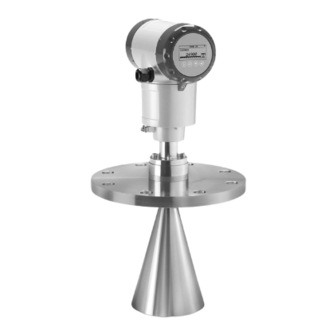
INTRODUCTION OPTIWAVE 5200 C 1.3 Device description This device is a 2-wire level transmitter that uses FMCW (Frequency Modulated Continuous Wave) / Radar technology. Radar is a non-contact technology. It measures the distance, level, mass, volume, flow rate and reflection of liquids, pastes and slurries .It is particularly suitable for the level measurement of corrosive and viscous products. -
Page 6: Terms And Definitions
INTRODUCTION OPTIWAVE 5200 C 1.5 Terms and definitions Diagnostic Coverage of dangerous failures Firmware Software embedded in the device. Failure In Time (1×10 failures per hour) FMCW Frequency-Modulated Continous-Wave. The measuring principle. For more data, refer to “Technical Data” in the handbook (document [N1]). -
Page 7: System Description
SYSTEM DESCRIPTION OPTIWAVE 5200 C 2.1 Peripheral equipment You can use the device with the equipment that follows: • A logic solver that can read 4...20 mA current input and low error alarm signals • A PC or workstation (this is used only to change parameters) ®... -
Page 8: Installation
INSTALLATION OPTIWAVE 5200 C WARNING! If the device is to agree with the requirements for functional safety given in IEC 61508, you must obey the installation instructions given in the handbook (document [N1]). The device must be installed by approved personnel. -
Page 9: Electrical Connection
ELECTRICAL CONNECTION OPTIWAVE 5200 C WARNING! If the device is to agree with the requirements for functional safety given in IEC 61508, you must obey the electrical connection instructions given in the handbook (document [N1]). The device must be installed by approved personnel. -
Page 10: Start-Up
START-UP OPTIWAVE 5200 C 5.1 General notes DANGER! Before you energize the device, make sure that the polarity and the supply voltage are correct. DANGER! Make sure that the device and the installation agree with the requirements of the Ex certificate of compliance. -
Page 11: Specification Of Safety Function
SPECIFICATION OF SAFETY FUNCTION OPTIWAVE 5200 C 6.1 Preliminary requirements WARNING! The data in this supplement only contains the data applicable to the SIL approval. The technical data for the standard version in the handbook (document [N1]) shall be valid in its current version, provided that it is not rendered invalid or replaced by this supplement. -
Page 12: Safety Function Characteristics
SPECIFICATION OF SAFETY FUNCTION OPTIWAVE 5200 C 6.2.3 Safety function characteristics The safety function uses only a 4...20 mA analog output signal to measure the level and give the device status. The analog output signal has an accuracy of ±2.5%. -
Page 13: Operation
OPERATION OPTIWAVE 5200 C 7.1 Conditions of use WARNING! Only approved personnel can change device settings. Keep a report of changes to the device settings. These reports must include the date, the menu item (e.g. 2.3.1 TANK HEIGHT), the old parameter and the new parameter. -
Page 14: Operation Mode
OPERATION OPTIWAVE 5200 C 7.3 Operation mode In operational conditions, the device continuously measures the distance between the tank connecting flange face / thread stop and the surface of the product. The operation mode of the device is shown in the flow chart that follows:... -
Page 15: Error Conditions
OPERATION OPTIWAVE 5200 C Error mode state Current output (error value) Is the current output setting correct? No. The current output setting is incorrect. Yes. The current output setting is correct. Is a new correct measurement available? No. A correct measurement is not available. -
Page 16: User Parameters
OPERATION OPTIWAVE 5200 C 7.5 User parameters INFORMATION! If you change a parameter set in one or more of the menu items that follow, this will have an effect on the safety function. 7.5.1 Limits for supervisor menu functions related to antenna configuration... -
Page 17: Limits For Supervisor Menu Functions Related To Device Configuration
OPERATION OPTIWAVE 5200 C Menu Function Function description Selection list Default value and comments 2.3.8 ANTENNA.TYP Type of antenna. For more data, PP Horn, refer to the "Technical data" PTFE Horn, chapter in the handbook. Metal. Horn, Wave Stick, Wave Guide 2.3.9... - Page 18 OPERATION OPTIWAVE 5200 C Menu Function Function description Selection list Default value and comments 2.4.3 SCALE 4mA This gives a measurement value to min.-max: Default value 4 mA. agrees with the customer order 2.4.4 SCALE 20mA This gives a measurement value to min.-max:...
- Page 19 OPERATION OPTIWAVE 5200 C Menu Function Function description Selection list Default value and comments 2.5.6 MULT.REF.EN. Multiple reflections will cause the YES, NO device to display smaller level readings. Objects in the tank, sharp corners, installation of the device on a large nozzle or at the centre of a dome roof, and low dielectric products (ε...
-
Page 20: Service
SERVICE OPTIWAVE 5200 C 8.1 Periodic maintenance You must obey the maintenance instructions given in the handbook (document [N1]). 8.2 Keep the device clean For more data, refer to “Service” in the handbook (document [N1]). 8.3 Availability of services The manufacturer offers a range of services to support the customer after expiration of the warranty. - Page 21 SERVICE OPTIWAVE 5200 C Equipment needed: • Device with the integrated display option • Process measurement and device configuration software (e.g. the DTM for PACTware™), if the device does not have the integrated display option • Ammeter • Reference device: an approved level meter or indicator Do a check of the 4 mA and the 20 mA settings: •...
- Page 22 SERVICE OPTIWAVE 5200 C Do a check of the low error alarm signal: • Enter the supervisor menu. For more data on how to get access to the supervisor menu, refer to the "Operation" chapter of the handbook (document [N1]).
-
Page 23: Calibration Procedure
SERVICE OPTIWAVE 5200 C 8.5 Calibration procedure 8.5.1 General notes If the antenna is not in the same customer order as the signal converter, it is necessary to calibrate the device. Equipment needed • A device with the integrated display option. -
Page 24: Current Output Check
SERVICE OPTIWAVE 5200 C 8.5.2 Current output check Do a check of the current output value: 4 mA • Energize the device. • Enter the Supervisor menu. • Push [> > > > ], [ ] and [> > > > ] to go to menu item 2.2.1 SET OUTPUT. Push [> > > > ] and then push [ ] or [ ] to move up or down the list to set the output to 4 mA. -
Page 25: Measuring Range Check (In Process Conditions)
SERVICE OPTIWAVE 5200 C 8.5.3 Measuring range check (in process conditions) The complete device (the signal converter, the process connection and the antenna) is installed on the tank in process conditions. We recommend that you use this procedure to do a measuring range check. -
Page 26: Troubleshooting
SERVICE OPTIWAVE 5200 C 8.6 Troubleshooting INFORMATION! • Modifications to the device are not permitted. Only approved personnel can repair the device. • If you find a problem, please contact your local representative. If the device must go back to the manufacturer, refer to "Returning the device to the manufacturer"... -
Page 27: Form (For Copying) To Accompany A Returned Device
SERVICE OPTIWAVE 5200 C 8.7.2 Form (for copying) to accompany a returned device Company: Address: Department: Name: Tel. no.: Fax no.: Manufacturer's order no. or serial no.: The device has been operated with the following medium: This medium is: water-hazardous... -
Page 28: Technical Data
TECHNICAL DATA OPTIWAVE 5200 C 9.1 General notes The device agrees with these conditions in the IEC 61508 standard: Condition Description The device operates in high The device continuously measures the distance to the surface of the demand or continuous mode of product in the tank. -
Page 29: Characteristics For The Device Safety Function
TECHNICAL DATA OPTIWAVE 5200 C 9.3 Characteristics for the device safety function Version Non-Ex / Ex i Ex d Firmware version Converter: 1.00.06; Sensor: 1.00.06 Board version Converter: 4000678801B; Converter: 4000678801B; Sensor: 4001105601B Sensor: 4001105601B Ex d barrier: 4000633801A Systematic capability... - Page 30 TECHNICAL DATA OPTIWAVE 5200 C Design Antenna options All basic antenna options Interface languages English, German, French, Italian, Spanish, Portuguese, Japanese, Chinese (Mandarin) and Russian Accuracy Resolution 1 mm / 0.04¨ Repeatability ±1 mm / ±0.04¨ Accuracy ±5 mm / ±0.2¨, when distance < 10 m / 33 ft;...
-
Page 31: Support For Sil-Approved Devices
TECHNICAL DATA OPTIWAVE 5200 C Electrical connections Power supply Terminals output - Non-Ex / Ex i: Terminals output - Non-Ex / Ex i: Terminals output - Non-Ex / Ex i: Terminals output - Non-Ex / Ex i: 12…30 VDC; min./max. value for an output of 22 mA at the terminal... -
Page 32: Appendix
APPENDIX OPTIWAVE 5200 C 10.1 Start-up report WARNING! Complete the start-up checklist before you energize the device. Please complete this start-up checklist and return it to the manufacturer. Are the polarity and the supply voltage correct? Ex-approved devices only: does the device and the installation agrees with the... -
Page 33: Proof Test Report Form (For Copying)
APPENDIX OPTIWAVE 5200 C 10.2 Proof test report form (for copying) CAUTION! Complete the report form that follows when you do a proof test. Proof tests For more data, refer to on page 20. Recorded by: Date: Unique device ID (e.g. serial number):... - Page 34 NOTES OPTIWAVE 5200 C www.krohne.com 02/2013 - 4001906202 - AD SIL OPTIWAVE 5200 R02 en...
- Page 35 NOTES OPTIWAVE 5200 C 02/2013 - 4001906202 - AD SIL OPTIWAVE 5200 R02 en www.krohne.com...
- Page 36 • Measuring systems for the marine industry Head Office KROHNE Messtechnik GmbH Ludwig-Krohne-Str. 5 47058 Duisburg (Germany) Tel.:+49 (0)203 301 0 Fax:+49 (0)203 301 10389 info@krohne.de The current list of all KROHNE contacts and addresses can be found at: www.krohne.com...
Need help?
Do you have a question about the OPTIWAVE 5200 C and is the answer not in the manual?
Questions and answers