Table of Contents
Advertisement
Quick Links
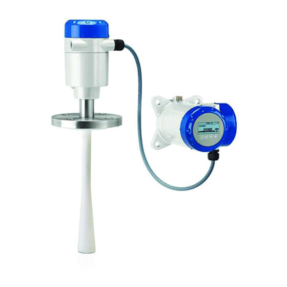
OPTIWAVE 5200 C/F
OPTIWAVE 5200 C/F
OPTIWAVE 5200 C/F
OPTIWAVE 5200 C/F
2-wire / 10 GHz Radar (FMCW) Level Meter
Supplementary Instructions for IECEx applications
Supplementary Instructions for IECEx applications
Supplementary Instructions for IECEx applications
Supplementary Instructions for IECEx applications
© KROHNE 09/2014 - 4001906103 - AD IECEX OPTIWAVE 5200 R03 en
Supplementary instructions
Supplementary instructions
Supplementary instructions
Supplementary instructions
Advertisement
Table of Contents

Related Manuals for KROHNE OPTIWAVE 5200


Summary of Contents for KROHNE OPTIWAVE 5200
- Page 1 2-wire / 10 GHz Radar (FMCW) Level Meter Supplementary Instructions for IECEx applications Supplementary Instructions for IECEx applications Supplementary Instructions for IECEx applications Supplementary Instructions for IECEx applications © KROHNE 09/2014 - 4001906103 - AD IECEX OPTIWAVE 5200 R03 en...
-
Page 2: Table Of Contents
3.7.1 How to connect the electrical cables ................... 26 3.7.2 Maximum intrinsically-safe values for the electrical circuit ..........26 3.7.3 Supply voltage ........................26 3.7.4 Electrical schematic ......................27 4 Start-up www.krohne.com 09/2014 - 4001906103 - AD IECEX OPTIWAVE 5200 R03 en... - Page 3 5.2 Keep the device clean..................... 29 5.3 Returning the device to the manufacturer..............29 5.3.1 General information......................29 5.3.2 Form (for copying) to accompany a returned device............30 6 Notes 09/2014 - 4001906103 - AD IECEX OPTIWAVE 5200 R03 en www.krohne.com...
-
Page 4: General Safety Information
Ex ia, Ex d ia / Ex ia tb and Ex ic versions are certified for use in hazardous areas by the DEKRA Certification B.V. under DEK 11.0060X. WARNING! Carefully read the IECEx approval certificate. Obey the boundary conditions. www.krohne.com 09/2014 - 4001906103 - AD IECEX OPTIWAVE 5200 R03 en... -
Page 5: Equipment Protection Levels (Epl)
Dust Group IIIA, IIIB and IIIC when fitted with appropriate options. It is certified for applications for which an EPL of Dc is necessary. The Ex ic approval is available only for devices with the FOUNDATION fieldbus or PROFIBUS PA option. 09/2014 - 4001906103 - AD IECEX OPTIWAVE 5200 R03 en www.krohne.com... -
Page 6: Iecex Nameplates
6 Cable entry type and size (M20×1.5 or ½ NPT) 7 Input voltage range and maximum current (4...20 mA passive - HART) / basic current (FF or PROFIBUS PA) www.krohne.com 09/2014 - 4001906103 - AD IECEX OPTIWAVE 5200 R03 en... - Page 7 Types of device protection (explosive atmosphere - dust), zones, maximum surface temperature, equipment protec- tion level and degree of ingress protection (if fitted with the appropriate cable glands) 09/2014 - 4001906103 - AD IECEX OPTIWAVE 5200 R03 en www.krohne.com...
-
Page 8: Installation
• locations where there is a risk of an increase in electrostatic charge caused by compressed air and dust, • locations near machines that use friction, • locations near systems that apply electrons as a spray (e.g. near electrostatic painting systems), www.krohne.com 09/2014 - 4001906103 - AD IECEX OPTIWAVE 5200 R03 en... -
Page 9: Operating Conditions
Wave-Guide EPDM FKM/FPM ® Kalrez 6375 PTFE Wave Horn PP Wave Horn Wave-Stick For more data, refer to "Pressure and temperature ranges" in the Installation chapter of the handbook. 09/2014 - 4001906103 - AD IECEX OPTIWAVE 5200 R03 en www.krohne.com... - Page 10 The temperature data that follows is applicable to devices that have the 4...20 mA passive - HART, PROFIBUS PA or FOUNDATION™ fieldbus output options. www.krohne.com 09/2014 - 4001906103 - AD IECEX OPTIWAVE 5200 R03 en...
- Page 11 PP Wave Horn PTFE Wave Horn Metallic Horn Metallic Horn Wave-Stick Wave-Guide Wave Guide (standard (high- temperature) temperature) [°C] [°F] [°C] [°F] [°C] [°F] [°C] [°F] [°C] [°F] T6...T2 09/2014 - 4001906103 - AD IECEX OPTIWAVE 5200 R03 en www.krohne.com...
- Page 12 [°C] [°F] [°C] [°F] [°C] [°F] [°C] [°F] [°C] [°F] T6...T2 1 Make sure that gasket temperature is in the specified limits. For more data, refer to the handbook. www.krohne.com 09/2014 - 4001906103 - AD IECEX OPTIWAVE 5200 R03 en...
- Page 13 , permitted depends on the temperature class: • = +60 ° C for class T6 • = +70 ° C for class T5 = +80 ° C for class T4 • 09/2014 - 4001906103 - AD IECEX OPTIWAVE 5200 R03 en www.krohne.com...
- Page 14 , permitted depends on the temperature class: = +60 C for class T6 • ° = +70 C for class T5 • ° = +80 C for class T4 • ° www.krohne.com 09/2014 - 4001906103 - AD IECEX OPTIWAVE 5200 R03 en...
- Page 15 +136 +140 +284 +131 +129 +150 +302 +124 +120 +160 +320 +170 +338 +180 +356 +190 +374 +200 +392 +210 +410 +220 +428 +230 +446 +240 +464 +250 +482 09/2014 - 4001906103 - AD IECEX OPTIWAVE 5200 R03 en www.krohne.com...
- Page 16 +153 +190 +374 +145 +149 +200 +392 +142 +147 +210 +410 +140 +145 +220 +428 +136 +142 +230 +446 +133 +140 +240 +464 +131 +138 +250 +482 +127 +135 www.krohne.com 09/2014 - 4001906103 - AD IECEX OPTIWAVE 5200 R03 en...
-
Page 17: Maximum Surface Temperature Of The Housing For Dust Applications
2.2.3 Process pressure Equipment protection level (EPL) Allowable process pressure [kPa] [psi] Ga/Gb 80…110 11.6…16 Others As per non-Ex device As per non-Ex device 1 Atmospheric pressure 09/2014 - 4001906103 - AD IECEX OPTIWAVE 5200 R03 en www.krohne.com... -
Page 18: Electrical Connections
How to open the Ex d / Ex t terminal compartment Figure 3-2: How to open the Ex d / Ex t terminal compartment 1 Cover stop 2 Terminal compartment cover www.krohne.com 09/2014 - 4001906103 - AD IECEX OPTIWAVE 5200 R03 en... -
Page 19: How To Close The Terminal Compartment
• Make sure that the terminal compartment cover is tight. • Use a 2.5 mm Allen wrench to attach the cover stop 1. • Make sure that the cover stop 1 screw is tight. 09/2014 - 4001906103 - AD IECEX OPTIWAVE 5200 R03 en www.krohne.com... -
Page 20: Terminal Tightening Capacity
Figure 3-3: Ex i applications: Terminals for the equipotential bonding system Figure 3-4: Ex d / Ex t applications: Terminals for the equipotential bonding system www.krohne.com 09/2014 - 4001906103 - AD IECEX OPTIWAVE 5200 R03 en... -
Page 21: Ex Ia Equipment
1 For a current output of 22 mA Level transmitter with the PROFIBUS PA or FOUNDATION fieldbus output option Minimum voltage at Maximum voltage at output terminal [VDC] output terminal [VDC] Output terminal Entity FISCO 17.5 09/2014 - 4001906103 - AD IECEX OPTIWAVE 5200 R03 en www.krohne.com... -
Page 22: Electrical Schematic
The signal cable (between the converter electronics and the probe end electronics) is supplied by the manufacturer for IECEx applications. The signal cable cannot be changed by the user. For more data, speak to the supplier. www.krohne.com 09/2014 - 4001906103 - AD IECEX OPTIWAVE 5200 R03 en... -
Page 23: Ex D Ia / Ex Ia Tb Equipment
2 Terminal (Ex d / Ex t) compartment INFORMATION! The flamepath dimensions are better than the values specified in the International Standard IEC 60079-1 (minimum length 13.9 mm and maximum gap 118 µ 09/2014 - 4001906103 - AD IECEX OPTIWAVE 5200 R03 en www.krohne.com... -
Page 24: How To Connect The Electrical Cables
Keep the grounding wire a minimum distance of 2 mm / 0.83 ¨ away from the output terminal. CAUTION! Make sure that you connect the load resistor to the positive side. www.krohne.com 09/2014 - 4001906103 - AD IECEX OPTIWAVE 5200 R03 en... - Page 25 The signal cable (between the converter electronics and the probe end electronics) is supplied by the manufacturer for IECEx applications. The signal cable cannot be changed by the user. For more data, speak to the supplier. 09/2014 - 4001906103 - AD IECEX OPTIWAVE 5200 R03 en www.krohne.com...
-
Page 26: Ex Ic Equipment
1 For a current output of 22 mA Level transmitter with the PROFIBUS PA or FOUNDATION fieldbus output option Minimum voltage at Maximum voltage at output terminal [VDC] output terminal [VDC] Output terminal Entity FISCO 17.5 www.krohne.com 09/2014 - 4001906103 - AD IECEX OPTIWAVE 5200 R03 en... -
Page 27: Electrical Schematic
The signal cable (between the converter electronics and the probe end electronics) is supplied by the manufacturer for IECEx applications. The signal cable cannot be changed by the user. For more data, speak to the supplier. 09/2014 - 4001906103 - AD IECEX OPTIWAVE 5200 R03 en www.krohne.com... -
Page 28: Start-Up
• Did you install the correct cable entries? Is the terminal compartment correctly sealed? • Does the optional purging system agree with Ex requirements? www.krohne.com 09/2014 - 4001906103 - AD IECEX OPTIWAVE 5200 R03 en... -
Page 29: Service
• such dangerous substances, to enclose a certificate with the device confirming that is safe to handle and stating the • product used. 09/2014 - 4001906103 - AD IECEX OPTIWAVE 5200 R03 en www.krohne.com... -
Page 30: Form (For Copying) To Accompany A Returned Device
We hereby confirm that there is no risk to persons or the environment through any residual media contained in the device when it is returned. Date: Signature: Stamp: www.krohne.com 09/2014 - 4001906103 - AD IECEX OPTIWAVE 5200 R03 en... -
Page 31: Notes
NOTES OPTIWAVE 5200 C/F 09/2014 - 4001906103 - AD IECEX OPTIWAVE 5200 R03 en www.krohne.com... - Page 32 Measuring systems for the marine industry Head Office KROHNE Messtechnik GmbH Ludwig-Krohne-Str. 5 47058 Duisburg (Germany) Tel.:+49 203 301 0 Fax:+49 203 301 103 89 info@krohne.com The current list of all KROHNE contacts and addresses can be found at: www.krohne.com...
Need help?
Do you have a question about the OPTIWAVE 5200 and is the answer not in the manual?
Questions and answers