Table of Contents
Advertisement
Quick Links
© KROHNE
7.30925.31.00
07.03.2003
Installation and
operating instructions
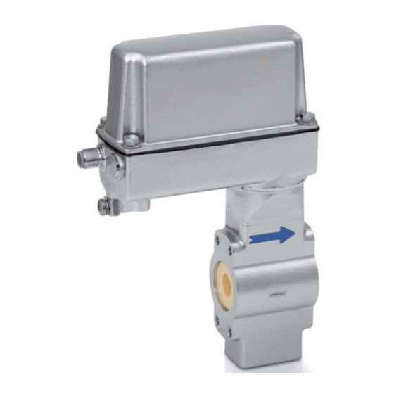
BATCHFLUX 5015 K
Compact electromagnetic
flowmeters
Please note!
Do not open the housing of the BATCHFLUX IFM 5015 K.
Danger of contamination with substances likely to destroy the
moisture barrier of the electronic equipment (e.g. if CIP or SIP
cleaned from the outside).
Therefore, please contact your KROHNE Service engineer
before you open the housing.
Advertisement
Table of Contents

Related Manuals for KROHNE BATCHFLUX 5015 K Series


Summary of Contents for KROHNE BATCHFLUX 5015 K Series
- Page 1 Do not open the housing of the BATCHFLUX IFM 5015 K. Danger of contamination with substances likely to destroy the moisture barrier of the electronic equipment (e.g. if CIP or SIP cleaned from the outside). Therefore, please contact your KROHNE Service engineer before you open the housing.
-
Page 2: Table Of Contents
Contents System description Standards and approvals Product liability and warranty Functional description BATCHFLUX IFM 5015 K Part A System installation and start-up 6 - 16 Installation in the pipeline 6 - 11 Important information Suggestions for installation Installation requirements 1.3.1 Position of flange 1.3.2 Example: centering and sealing the primary head 1.3.3 Grounding Installation of the primary head... - Page 3 Danger of contamination with substances likely to destroy the moisture barrier of the electronic equipment (e.g. if CIP or SIP cleaned from the outside). Therefore, please contact your KROHNE Service engineer before you open the housing. Installation and operating instructions...
-
Page 4: System Description
In addition, the “General conditions of sale“ forming the basis of the purchase contract are applicable. If BATCHFLUX IFM 5015 K flowmeters need to be returned to KROHNE, please note the information given on the last-but-one page of these instructions. KROHNE regret that they cannot repair or check your flowmeter(s) unless these are accompanied by the completed form sheet. -
Page 5: Functional Description Batchflux Ifm 5015 K
Functional description BATCHFLUX IFM 5015 K The volume to be filled into the container is measured “in line“ by means of the electromagnetic flowmetering system. The batch controller closes the filling valve once the preset filling volume has been reached. It is always the preset target volume that is filled into the container. -
Page 6: Part A System Installation And Start-Up
Part A System installation and start-up Installation in the pipeline Important information The following recommendations should be observed to ensure proper functioning of the flowmeter – PLEASE NOTE. • • Measuring tube must be completed Heat-insulated pipelines: do not insulate filled at all times. -
Page 7: Suggestions For Installation
Suggestions for installation Pumps To avoid measuring errors due to Do not install flowmeter on pump suction side air inclusion and vacuum, please observe the following: Highest point of pipe run (Air bubbles collect in measuring tube - faulty measurements!) Open feed or discharge Install meter in low section of pipe Preferred... -
Page 8: Installation Requirements
Installation requirements Items supplied with flowmeter Requirements • BATCHFLUX IFM 5015 K compact Use in the food industry flowmeter in the version as ordered The IFM 5015 K is specifically suitable for use • Installation and operating instructions, in the food and beverage industry or similar as agreed sterile processes. -
Page 9: Position Of Flange
1.3.1 Position of flanges 1.3.3 Grounding Install flowmeter in line with the pipe axis. Pipe flange faces must be parallel to each other, max. allowable deviation: ≤ 0.5 mm ≤ 0.02" – L 1.3.2 Example: centering and sealing the primary head Functional ground, wire >... -
Page 10: Installation Of The Primary Head
Installation of the primary head 1.4.1 Device description 1.4.2 Installation of the IFM 5015 K • Position gaskets (12) in the pipe flanges. • Type and location of gaskets as specified by the manufacturer of the filling machine (see Sect. 1.3.2 “Centering of the primary head”). -
Page 11: Size Of Connections
Size of connections 1.5.1 Fastening with tie bolts All dimensions in mm (inches) Flange-material: AISI 300 series O-ring material: 3A standard 18-03 Meter size Centering device, pipe connection O-Ring Dimensions inches 75 Shore 25.5 on request -0.05/-0.15 -0.05/-0.15 (0.24) (1.00) (1.18 (0.06 on request... -
Page 12: Fastening With Tie Bolts (Option)
1.5.2 Fastening with bolts (option) All dimensions in mm (inches) Flange-material : AISI 300 series O-ring material : 3A standard 18-03 Meter size Centering device, pipe connection O-ring Screw thread (option) gaskets 2× M4 4× M6 75 Shore inches 25.5 on request -0.05/-0.15 -0.05/-0.15... -
Page 13: Electrical Connection
Electrical connection Important information • Be sure to take note of the following Protect the flowmeter from direct radiant information in order to ensure proper heat (e.g. hot-product tanks), insulate if functioning of the signal converter. necessary. • Please note: Do not expose flowmeter to intense Overvoltage class: vibration. -
Page 14: Power Supply And Outputs
Power supply and outputs Standard 4-pin connector M12x1 for 24 V DC power supply and passive pulse output Standard + 24 V pulse output pulse output ⊥ ground Pin assignment Pulse output passiv ground power pulse output 24 Volt DC ≤... -
Page 15: Start-Up
Danger of contamination with substances likely to destroy the moisture barrier of the electronic equipment (e.g. if CIP or SIP cleaned from the outside). Therefore, please contact your KROHNE Service engineer before you open the housing. • The measurement status is signalled by the... -
Page 16: Factory Settings
Factory settings All operating data are factory-set according to The factory setting for the current and pulse your order specifications. outputs may occasionally cause measuring errors, particularly in the case of volume flow To facilitate easy and rapid initial start-up, counting. -
Page 17: Part B Ifc 015 Signal Converter
Danger of contamination with substances likely to destroy the moisture barrier of the electronic equipment (e.g. if CIP or SIP cleaned from the outside). Therefore, please contact your KROHNE Service engineer before you open the housing. 1 3 6 . 4 9... -
Page 18: Operating And Check Elements
Operating and check Function of the keys elements The cursor, flashing part of display, has a grey background in the following descriptions. The following operating elements are featured on the hand-held communicator HHT 010: To start operator control Measuring mode HHT 010 1 3 . - Page 19 To change numbers Increase number ↑ 3 9 7 . 3 5 3 9 7 . 4 5 / h r ↓ / h r Decrease number To shift cursor (flashing position) Shift to right → 3 9 7 . 3 5 3 9 7 .
-
Page 20: Table Of Settable Functions
Table of settable functions Abbreviatioins used Fct. Text Description and settings OPERATION Operations menu Nominal size, meter size FULL.SCALE Full-scale range for flowrate Q Highest frequency of the pulse output 100% Select unit Lowest frequency of the pulse output • m /hr •... - Page 21 Fct. Text Description and settings Fct. Text Description and settings L.F. CURRENT I Current output I CUTOFF Low-flow cutoff (SMU) No hardware available • OFF (fixed values: → Select function for current ON = 0.1% / output I FUNCTION I OFF = 0.2%, •...
- Page 22 Fct. Text Description and settings Fct. Text Description and settings → Set pulse value per unit TEST Test menu volume (appears only when VALUE P TEST Q Test of range Q “PULSE/VOL.“ set under Precautionary query “SELECT.P“ above) • SURE NO •...
- Page 23 Fct. Text Description and settings Fct. Text Description and settings INSTALL. Installation menu → Magnetic field frequency FIELD LANGUAGE Select language for Do not change setting ! FREQ. display texts Values 1/2, 1/6 and 1/18 • GB / USA (English) of 50 Hz or 60 Hz, •...
- Page 24 Fct. Text Description and settings Fct. Text Description and settings ZERO Zero calibration → Set text for required flow unit (max. 3 characters) Note: Carry out only when flow TEXT is “0“ and measuring tube is Factory-set: “hr“ (= hour). TIME completely filled! Characters assignable to...
-
Page 25: Error Messages In Measuring Mode
Error messages in measuring mode The following list gives all errors that are likely to occur during process flow measurement. Errors are shown in the display when “YES“ is set in Fct. 1.4 DISPLAY, subfunction “DISP.MSG.“. Error message Discription of error Error clearance LINE INT. -
Page 26: Resetting Totalizers And Deleting Error Messages, Reset / Quit Menu
Resetting totalizer and deleting error messages, RESET / QUIT menu Cancel error messages in RESET / QUIT menu Display Description - - - - - - - - - - - - / - - - Measuring mode ↵ CodE 2 Key in Entry Code 2 for RESET/QUIT menu: →... - Page 27 Notes Installation and operating instructions BATCHFLUX...
-
Page 28: Description Of Functions
(applies to HHT 010-display cleaned from the outside). and all outputs) • ONLY I + S (only valid for HHT 010 display, Therefore, please contact your KROHNE current and status outputs, Service engineer before you open the no current output, housing. -
Page 29: Display With Hht 010
Display with HHT 010 → DISP.MSG. = Additional messages Fct. 1.4 DISPLAY required in measuring mode, press key → Press key ↵ . • (no other messages) → DISP.FLOW = Select unit for display • (display other messages, of flowrate, press key → e.g. -
Page 30: Current Output I
Current output I Pulse output P No HARDWARE! Fct. 1.6 PULS.OUTP. P Function must be set to “OFF”. Press key → . Fct. 1.5 CUR.OUTP. I (not available, no → FUNCTION P = Select function for the HARDWARE !) pulse output, press key → Press key →... - Page 31 → VALUE P = Set pulse value per unit volume, (appears only when “PULSE/VOL.“ has been set under “SELECT P“) press key → • XXXX PulS/m • XXXX PulS/Liter • XXXX PulS/US.Gal • XXXX PulS/ user-defined unit, factory-set is “Liter“, see Sect. 5.12. Select with keys ↑...
-
Page 32: Status Output S (Option)
Status output S (option) No HARDWARE! Function must be set to “OFF”. Transfer to number setting with key ↵ , 1st digit (cursor) flashes. Change flashing digit (cursor) with keys ↑ and ↓ , shift cursor 1 Fct. 1.7 IND. OUTP. S place to right or left with keys →... -
Page 33: Entry Code
5.10 Entry Code Fct. 3.4 ENTRY CODE Press key → . Selection (no code, press key → • to enter setting mode) (enter setting mode with key → • and Code 1: → → → ↵ ↵ ↵ ↑ ↑ ↑ ) Select with keys ↑... -
Page 34: User-Definable Unit
5.12 User-definable unit → TEXT TIME = Set text für required time, Fct. 3.5 USER UNIT press key → Press key → . • hr (max. 3 places, factory-set is “hr = hour“) → TEXT VOL. = Set the text for user- Characters assignable to each place: defined flow unit, press key →... -
Page 35: F/R Mode, Forward / Reverse Flow Measurement
5.13 F/R mode, forward / reverse flow measurement • • Refer to Sect. 2.3 for electrical Set the status indication output to connection of the outputs. “F/R INDIC.“, see Fct. 1.7. • • Set the current and / or pulse output to Define direction of forward (normal) “2 DIR.“, see Fct. -
Page 36: Part C Special Applications, Functional Checks And Service
Danger of contamination with substances likely to destroy the moisture barrier of the electronic equipment (e.g. if CIP or SIP cleaned from the outside). Therefore, please contact your KROHNE Service engineer before you open the housing. Operation via HHT 010 hand-... -
Page 37: Functional Checks
• Switch on the system and wait 15 minutes. • Press the following keys for zero Therefore, please contact your KROHNE measurement Service engineer before you open the housing. Displayed Description → If “YES“ is set under Fct. 3.4 ENTRY CODE, key-in the 9- keystroke CODE 1: →... -
Page 38: Test Of Measuring Range Q, Fct
Q (for set full-scale range 100% see Fct. 1.1 FULL SCALE). Therefore, please contact your KROHNE • Power the system. Service engineer before you open the • Press the following keys for this test: housing. -
Page 39: Hardware Information And Error Status, Fct
(2x) 3x ↵ - - - - - - - - - - - - - / - - - Measuring mode If you need to return your flowmeter to KROHNE, please refer to the last-but-one page of these Instructions ! Installation and operating instructions... -
Page 40: Service
Danger of contamination with substances likely to destroy the moisture barrier of the electronic equipment (e.g. if CIP or SIP cleaned from the outside). Therefore, please contact your KROHNE Service engineer before you open the housing. Important advice for removing the flowmeter from the pipeline –... -
Page 41: Removal Of The Electronics Unit
Danger of contamination with substances likely to destroy the moisture barrier of the electronic equipment (e.g. if CIP or SIP cleaned from the outside). Therefore, please contact your KROHNE Service engineer before you open the housing. Cover, signal converter Gasket... -
Page 42: Part D Technical Data, Block Diagram And Measuring Principle
Part D Technical Data, block diagram and measuring principle 10 Technical data 10.1 Flow during filling, and fill volume Filling times > 1.5 s, Meter size Optimum flowrate for filling filling volume ..DN mm inches ml/s US Gal/min US Gal 0.048 - 0.159 ≥... -
Page 43: Signal Converter
Operator control All operating data factory-set to your specifications. Available as option for change of operating data: - HHT 010 hand-held terminal or - KROHNE software for operator control via PC. Options connected to the IMoCom interface Pulse output passive circuit... -
Page 44: Error Limits At Reference Conditions
10.4 Error limits at reference conditions = Error in % of MV = measured value Pulse output DN 2.5 – 6 “ – “ DN 10 – 40 “ – 1 “ at flow velocity of ... v ≥ 1 m/s ≥ 3.3 ft/s F <... -
Page 45: Dimensions And Weights
10.5 Dimensions and weights in mm (inches) DN 2.5 –15 / “ – ½“ miniature circular connector series 713, 4-pin option: ventilation flow direction option: 4 x M6 bolt hole on both sides (section M-M) Meter size Diameter d Weight inches (inches) (0.24) -
Page 46: Instrument Nameplates
DN 25 – 40 / 1“ – 1½“ miniature circular connector series 713, 4-pin Meter size Dimensions in mm (inches) Weight inches (lb) (2.28) 200 (7.87) 66 (2.68) 34 (1.34) 1.6 (3.6) (3.27) 215 (8.46) 81 (3.19) 42 (1.65) 2.3 (5.1) (3.27) 215 (8.46) 81... -
Page 47: Block Diagram
11 Block diagram The IFC 015 signal converter consists of 3 Functional group 3 consists of passive FET functional groups. optocouplers to allow control of electronic and electromechanical totalizers. This group is Functional group 1 contains an input electrically separated from the other groups. amplifier, and a high-resolution analog/digital converter (ADC) that is controlled and monitored by microprocessor µP 1. - Page 48 12 Measuring principle Flowmeter for electrically conductive Thus, the induced voltage is proportional to the liquids. mean flow velocity, when the field strength is Measurement is based on Faraday’s law constant. Inside the electromagnetic flowmeter, of induction, according to which a voltage the liquid passes through a magnetic field is induced in an electrically conductive applied perpendicular to the direction of flow.
-
Page 49: Measuring Principle
Part E Annex Index Keyword Section-No. Fct-No. Keyword Section-No. Fct-No. Function of keys 4.1 - 4.3 Functional description page 5 Abbreviations Function(s) ADC = analog/digital converter Functional ground FE 1.3.3,2.1, 2.2 Ambient temperature 1.1.1, 10.6 Function column 4.1, Analog/digital converter = ADC Functional check 7.1 ff ANSI flanges... -
Page 50: Part E Annex
Keyword Section-No. Fct-No. Keyword Section-No. Fct-No. Number format of display 5.4, 5.5 S = status output 2.3.2, 4.4, 5.7 Safety conductor PE 1.2.3, 2.2 Scope of supply Operating pressure 10.5 Signalling cable A 1.3.4, 10.4 Option = add-on equipment 4.2, 6.1, Signal converter IFC 015 = HHT 010 10.3-10.5 ,...
Need help?
Do you have a question about the BATCHFLUX 5015 K Series and is the answer not in the manual?
Questions and answers