Table of Contents
Advertisement
Quick Links
OPTIWAVE 5200 C/F
OPTIWAVE 5200 C/F
OPTIWAVE 5200 C/F
OPTIWAVE 5200 C/F
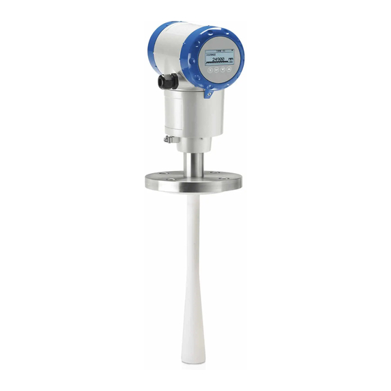
Radar (FMCW) Level Transmitter for liquids in storage
and process applications
Supplementary Instructions for ATEX applications
Supplementary Instructions for ATEX applications
Supplementary Instructions for ATEX applications
Supplementary Instructions for ATEX applications
© KROHNE 11/2016 - 4001905804 - AD ATEX OPTIWAVE 5200 R04 en
Supplementary Instructions
Supplementary Instructions
Supplementary Instructions
Supplementary Instructions
Advertisement
Table of Contents

Related Manuals for KROHNE OPTIWAVE 5200 C/F


Summary of Contents for KROHNE OPTIWAVE 5200 C/F
- Page 1 Radar (FMCW) Level Transmitter for liquids in storage and process applications Supplementary Instructions for ATEX applications Supplementary Instructions for ATEX applications Supplementary Instructions for ATEX applications Supplementary Instructions for ATEX applications © KROHNE 11/2016 - 4001905804 - AD ATEX OPTIWAVE 5200 R04 en...
-
Page 2: Table Of Contents
CONTENTS OPTIWAVE 5200 C/F 1 General safety information 1.1 Scope of the document..................... 4 1.2 Device description ......................4 1.3 Standards and approvals....................4 1.4 Device categories ......................5 1.4.1 Ex ia-approved devices ......................5 1.4.2 Ex db ia / Ex ia tb-approved devices ..................5 1.4.3 Ex ic-approved devices ...................... - Page 3 CONTENTS OPTIWAVE 5200 C/F 5 Service 5.1 Periodic maintenance..................... 32 5.2 Keep the device clean..................... 32 5.3 Manufacturer ........................32 5.4 Returning the device to the manufacturer..............33 5.4.1 General information......................33 5.4.2 Form (for copying) to accompany a returned device............34...
-
Page 4: General Safety Information
GENERAL SAFETY INFORMATION OPTIWAVE 5200 C/F 1.1 Scope of the document These instructions are applicable only to the explosion-protection version of the radar level transmitter. For all other data, use the Quick Start and Handbook. If you do not have these documents, please contact the nearest office or download them from the manufacturer's internet site. -
Page 5: Device Categories
GENERAL SAFETY INFORMATION OPTIWAVE 5200 C/F 1.4 Device categories 1.4.1 Ex ia-approved devices The Ex ia-approved device is suitable for use in potentially explosive atmospheres of all flammable substances in Gas Groups IIA, IIB and IIC. It is certified for applications requiring Category 1/2 G (gases, vapours or mists) and EPL Ga/Gb equipment or 2 G and EPL Gb equipment when fitted with the appropriate options. -
Page 6: Atex Nameplates
GENERAL SAFETY INFORMATION OPTIWAVE 5200 C/F 1.5 ATEX nameplates Signal converter housing (compact and remote (field) versions) Figure 1-1: Nameplate on the signal converter housing (compact and remote (field) versions) 1 ATEX certification number 2 Equipment approval category (explosive atmosphere – gas), types of device protection including approved Gas Groups and temperature classes (T6...T4 or T3 or T2 –... - Page 7 GENERAL SAFETY INFORMATION OPTIWAVE 5200 C/F Antenna housing (remote (field) version) Figure 1-2: Nameplate on the antenna housing (remote (field) version) 1 ATEX certification number 2 Equipment approval category (explosive atmosphere – gas), types of device protection including approved Gas Groups, temperature classes (T6...T4 or T3 or T2 –...
-
Page 8: Installation
INSTALLATION OPTIWAVE 5200 C/F 2.1 Precautions 2.1.1 General notes WARNING! When you install the device, obey the conditions in the EU-Type Examination certificate. These conditions include: The special conditions for safe use. • The Essential Health and Safety Requirements. •... -
Page 9: Electrostatic Discharge
INSTALLATION OPTIWAVE 5200 C/F 2.1.2 Electrostatic discharge DANGER! Risk of electrostatic discharge from the painted surfaces of the aluminium housing and the Wave Horn and Wave-Stick antennas made of PP or PTFE. DANGER! Take the necessary antistatic precautions if: you handle the device in potentially explosive atmospheres, •... -
Page 10: Optional Purging System
INSTALLATION OPTIWAVE 5200 C/F 2.1.3 Optional purging system The purging system is supplied as an option for devices that have Metallic Horn antennas with a minimum flange size of DN150. Figure 2-2: Optional purging system 1 G ¼ threaded connection for purging system (the plug is supplied by the manufacturer) -
Page 11: Optional Heating/Cooling System
INSTALLATION OPTIWAVE 5200 C/F 2.1.4 Optional heating/cooling system The heating/cooling system is supplied as an option for devices that have Metallic Horn antennas with a minimum flange size of DN150. Figure 2-3: Optional heating/cooling system 1 G ¼ threaded connection for the heating/cooling system inlet (the plug is supplied by the manufacturer) 2 G ¼... -
Page 12: Operating Conditions
INSTALLATION OPTIWAVE 5200 C/F 2.2 Operating conditions The allowable ambient temperature and corresponding flange temperature range for the device depends on the temperature classes marked on the nameplate. 2.2.1 Ambient and flange temperature The ATEX equipment category, IEC equipment protection level and temperature class give the ambient temperature and related flange temperature ranges for the device. - Page 13 INSTALLATION OPTIWAVE 5200 C/F WARNING! Compact version only: If the device is used in a potentially explosive atmosphere that contains dust, do not install the device on the side of the tank. If the device must operate at a high process temperature, make sure that the maximum flange temperature and maximum ambient temperature are not more than the values given in the table.
- Page 14 INSTALLATION OPTIWAVE 5200 C/F Compact version Equipment category 2 G or EPL Gb: Ex ia and Ex db ia devices Equipment category 3 G or EPL Gc: Ex ic devices Temperature Maximum ambient temperature Max. flange class temperature PP Wave Horn...
- Page 15 INSTALLATION OPTIWAVE 5200 C/F Remote (Field) versions (antenna housing only) Equipment category 1/2 G or EPL Ga/Gb: Ex ia and Ex db ia devices Temperature Maximum ambient temperature Max. flange class temperature PP Wave Horn PTFE Wave Horn Metallic Horn...
- Page 16 INSTALLATION OPTIWAVE 5200 C/F Remote (Field) version (antenna housing only) Equipment category 2 G or EPL Gb: Ex ia and Ex db ia devices Equipment category 3 G or EPL Gc: Ex ic devices Temperature Maximum ambient temperature Max. flange...
- Page 17 INSTALLATION OPTIWAVE 5200 C/F Compact and Remote (Field) versions - PP and PFTE Wave Horn antennas Equipment category 1/2 D, 2 D or EPL Da/Db, Db: Ex ia and Ex ia tb devices Equipment category 3 D or EPL Dc: Ex ic devices...
- Page 18 INSTALLATION OPTIWAVE 5200 C/F Compact and Remote (Field) versions - Metallic Horn and Wave Guide antennas Equipment category 1/2 D, 2 D or EPL Da/Db, Db: Ex ia and Ex ia tb devices Equipment category 3 D or EPL Dc: Ex ic devices...
-
Page 19: Maximum Surface Temperature Of The Housing For Dust Applications
INSTALLATION OPTIWAVE 5200 C/F 2.2.2 Maximum surface temperature of the housing for dust applications WARNING! Equipment category 1/2 D, 2 D, 3 D or EPL Da/Db, Db, Dc: Ex ia, Ex ia tb and Ex ic devices only Equipment category 1/2 D, 2 D, 3 D or EPL Da/Db, Db, Dc: Ex ia, Ex ia tb and Ex ic devices only... -
Page 20: Electrical Connections
ELECTRICAL CONNECTIONS OPTIWAVE 5200 C/F 3.1 General notes WARNING! • De-energize the circuit. Use the applicable cable glands for the cable entry openings in the housing (M20×1.5 or • NPT). For the cable entry size, refer to the device nameplate. - Page 21 ELECTRICAL CONNECTIONS OPTIWAVE 5200 C/F Equipment needed (not supplied) • For Ex i-approved devices: 3 mm Allen wrench. • For Ex d- / Ex t-approved devices: 2.5 mm Allen wrench. INFORMATION! Ex i applications Ex i applications Ex i applications...
-
Page 22: How To Close The Terminal Compartment
ELECTRICAL CONNECTIONS OPTIWAVE 5200 C/F 3.2.2 How to close the terminal compartment Ex i applications • Attach the terminal compartment cover 2. Turn the terminal compartment cover carefully to prevent damage to the thread and the gasket. • Make sure that the terminal compartment cover is tight. -
Page 23: Equipotential Bonding System
ELECTRICAL CONNECTIONS OPTIWAVE 5200 C/F 3.4 Equipotential bonding system Compact version There is a terminal at the bottom of the converter that can be used as an equipotential bonding conductor. Connect the device to the equipotential bonding system for the hazardous location. -
Page 24: Ex Ia Equipment
ELECTRICAL CONNECTIONS OPTIWAVE 5200 C/F 3.5 Ex ia equipment 3.5.1 How to connect the electrical cables Refer to the handbook for data about the device terminals. Cable glands are supplied on customer demand. If you supply the cable glands, this part must have a degree of ingress protection IP≥6X (EN 60529). -
Page 25: Electrical Schematic
ELECTRICAL CONNECTIONS OPTIWAVE 5200 C/F 3.5.4 Electrical schematic Level transmitter with the 4...20 mA passive - HART output option Figure 3-5: Electrical schematic for Ex ia-approved equipment with the 4...20 mA passive - HART output option Level transmitter with the FOUNDATION™ fieldbus or PROFIBUS PA output option Figure 3-6: Electrical schematic for Ex ia-approved equipment with the FOUNDATION™... -
Page 26: Ex Db Ia / Ex Ia Tb Equipment
ELECTRICAL CONNECTIONS OPTIWAVE 5200 C/F 3.6 Ex db ia / Ex ia tb equipment 3.6.1 General notes Ex db ia- and Ex ia tb-approved equipment have two separate compartments. The electronics in the electronics block compartment are Ex ia-approved and the terminals compartment is Ex d / Ex t-approved. -
Page 27: Supply Voltage
ELECTRICAL CONNECTIONS OPTIWAVE 5200 C/F WARNING! Use only Ex d-approved cable glands and plugs for Ex d applications. Use only Ex t-approved cable glands and plugs for Ex t applications. Do not remove more than 6 mm / 0.2 of insulation from the wire. - Page 28 ELECTRICAL CONNECTIONS OPTIWAVE 5200 C/F Level transmitter with the 4...20 mA passive - HART output option Figure 3-9: Electrical schematic for Ex db ia / Ex ia tb-approved equipment (with galvanic isolation) Figure 3-10: Electrical schematic for Ex db ia / Ex ia tb-approved equipment (without galvanic isolation)
-
Page 29: Ex Ic Equipment
ELECTRICAL CONNECTIONS OPTIWAVE 5200 C/F 3.7 Ex ic equipment 3.7.1 How to connect the electrical cables Refer to the handbook for data about the device terminals. Cable glands are supplied on customer demand. If you supply the cable glands, this part must have a degree of ingress protection IP≥6X (EN 60529). -
Page 30: Electrical Schematic
ELECTRICAL CONNECTIONS OPTIWAVE 5200 C/F 3.7.4 Electrical schematic Level transmitter with the 4...20 mA passive - HART output option Figure 3-12: Electrical schematic for Ex ic-approved equipment with the 4...20 mA passive - HART output option Level transmitter with the FOUNDATION™ fieldbus or PROFIBUS PA output option Figure 3-13: Electrical schematic for Ex ic-approved equipment with the FOUNDATION™... -
Page 31: Start-Up
START-UP OPTIWAVE 5200 C/F WARNING! Make sure that it is safe to supply electrical power. Do a start-up check: • Are the wetted components (gasket, flange and antenna) resistant to corrosion by the tank product? • Does the information given on the nameplate agree with the application? •... -
Page 32: Service
2 Allée des Ors – B.P. 98 26103 Romans-sur-Isère CEDEX France If the serial number on the device nameplate starts with the letter "S", this device is made by: KROHNE Measurement Technology (Shanghai) Co., Ltd. Minshen Road 555 Songjiang Industrial Zone Shanghai 201612 China If you need to return your device for inspection or repair, make sure that you send it to the correct manufacturer and obey the instructions that follow. -
Page 33: Returning The Device To The Manufacturer
SERVICE OPTIWAVE 5200 C/F 5.4 Returning the device to the manufacturer 5.4.1 General information This device has been carefully manufactured and tested. If installed and operated in accordance with these operating instructions, it will rarely present any problems. CAUTION! Should you nevertheless need to return a device for inspection or repair, please pay strict... -
Page 34: Form (For Copying) To Accompany A Returned Device
SERVICE OPTIWAVE 5200 C/F 5.4.2 Form (for copying) to accompany a returned device CAUTION! To avoid any risk for our service personnel, this form has to be accessible from outside of the packaging with the returned device. Company: Address: Department: Name: Tel. -
Page 35: Notes
NOTES OPTIWAVE 5200 C/F 11/2016 - 4001905804 - AD ATEX OPTIWAVE 5200 R04 en www.krohne.com... - Page 36 • Process Analysis • Services Head Office KROHNE Messtechnik GmbH Ludwig-Krohne-Str. 5 47058 Duisburg (Germany) Tel.: +49 203 301 0 Fax: +49 203 301 10389 info@krohne.com The current list of all KROHNE contacts and addresses can be found at: www.krohne.com...
Need help?
Do you have a question about the OPTIWAVE 5200 C/F and is the answer not in the manual?
Questions and answers