KROHNE ALTOSONIC V Installation Manual
5-beam ultrasonic flowmetering system
Hide thumbs
Also See for ALTOSONIC V:
- Reference manual (64 pages) ,
- Addition to the installation and operating instructions (28 pages)
Table of Contents
Advertisement
ALTOSONIC V
5-beam ultrasonic flowmetering system
operating and installation instructions
UFC-V/...-EEx Flow Converter
UFS 500 F/5STR-EEx Flow Sensor
UFP-V Flow Processor
ALTOSONIC V
Ultrasonic flow Processor
Electrical & Mechanical Installation
Soware Version 0300
ALTOSONIC V
ALTOSONIC V
5-beam ultrasonic flowmetering system
Operating and installation instructions
UFC-V/...-EEx Flow Converter
UFS 500 F/5STR-EEx Flow Sensor
UFP-V Flow Processor
ALTOSONIC V
Ultrasonic flow Processor
Electrical & Mechanical Installation
Software Version 0300
© KROHNE 04/2012 MA ALTOSONIC V R02 en
Installation Manual
Advertisement
Table of Contents

Related Manuals for KROHNE ALTOSONIC V


Summary of Contents for KROHNE ALTOSONIC V
- Page 1 ALTOSONIC V 5-beam ultrasonic flowmetering system Operating and installation instructions UFC-V/…-EEx Flow Converter UFS 500 F/5STR-EEx Flow Sensor UFP-V Flow Processor ALTOSONIC V Ultrasonic flow Processor Electrical & Mechanical Installation Software Version 0300 © KROHNE 04/2012 MA ALTOSONIC V R02 en...
- Page 2 Install and connect cabling proper to exclude damage or harmful situations. If the instrument does not operate normally, refer to the service instructions or refer to qualified KROHNE service engineers. There are no operator-serviceable parts inside the instrument.
- Page 3 This manual and all other documents are subject to change without prior notice. KROHNE will not be liable for any damage of any kind by using its instrument, including, but not limited to direct, indirect, incidental, punitive and consequential damages.
- Page 4 Kerkeplaat 12 3313 LC Dordrecht The Netherlands For information, maintenance or service please contact your nearest local KROHNE representative or refer to our website www.krohne.com. No changes may be made to the devices. Unauthorized changes might affect the explosion safety of the devices.
-
Page 5: Table Of Contents
ALTOSONIC V Table of Contents Introduction ..................6 Cautions ......................6 Unpacking and inspection ................6 System description ..................7 Approvals ......................8 Safety instructions ..................8 Mechanical installation ..............10 Ultrasonic Flow Sensor (UFS-V) ..............10 Ultrasonic Flow Converter UFC-V ..............11 Ultrasonic Flow Processor UFP-V including I/O rack ......... -
Page 6: Introduction
1. Introduction 1.1 Cautions Refer all maintenance or service to trained KROHNE service engineers. Mains power shall be disconnected from the product before performing any maintenance. This product is prepared for and can only function with the rated mains voltage as indicated on the type plate. This product is a Class 1 device (earthed) and requires a correct connection to protective earth. -
Page 7: System Description
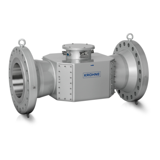
INTRODUCTION ALTOSONIC V 1.3 System description The ALTOSONIC V is a high precision instrument designed for linear, bi/directional flow measurement of liquids. The ALTOSONIC V is partly positioned in a potential hazardous environment and partly in a non-hazardous environment. The Flow Sensor UFS-V and the Flow Converter UFC-V are designed and factory prepared to function in a potential explosive environment. -
Page 8: Approvals
EEx -d protection 1.4 Approvals EMC, Electromagnetic Compatibility Directive The ALTOSONIC V flowmeter system complies with the requirements of the harmonized standards under the EMC directive 89/336/EEC. Pressure Equipment Directive The KROHNE organization complies with the requirements of Module H of the Pressure Equipment Directive 97/23/EC (full quality assurance). - Page 9 INTRODUCTION ALTOSONIC V The UFP-V Flow Processor and I/O rack are designed to operate safely under the following conditions: Indoor use or mounted in a suitable housing usable up to protection category according EN IEC 60529 of the housing ...
-
Page 10: Mechanical Installation
Avoid damaging the sealing of the sensor covers. Installation location and position As the ALTOSONIC V is used in hydro carbon pipe lines, be aware of potentially explosive atmospheres. Local standards and regulations must be respected. The sensor axis must be approximately horizontal even if the flowmeter is installed in slightly ascending horizontal pipe runs. -
Page 11: Ultrasonic Flow Converter Ufc-V
MECHANICAL INSTALLATION ALTOSONIC V Do not expose the sensor unit to intensive vibrations. Support of the flow sensor is only allowed at the in- and outlet sections near the flow meter. Gas inclusion To avoid measuring errors due to gas inclusion, if necessary adequate measures have to be taken to reduce. -
Page 12: Ultrasonic Flow Processor Ufp-V Including I/O Rack
482x266x307 mm, mass is about 17 kg, maximum power 260W. Standard this flow computer is equipped with CPU and several I/O boards. One of the boards is KROHNE specific. For the cable connections, power I/O etc. an I/O rack is supplied, 19” 4U high. The certified unit is containing all terminals for connection to mains and PE (protective earth), the terminals to and/or from auxiliary equipment, I/O-modules and the interface card with the flow processor. -
Page 13: Electrical Installation
Provide a water drip point (U bend in cable) Conduits The described standard version of ALTOSONIC V is equipped with cable glands for the use of harmonized cable. In countries where the electrical codes prescribe conduits, the mounted cable entries shall satisfy the IP protection class, e.g. NEMA 4 or 4X. -
Page 14: Power Connection
ELECTRICAL INSTALLATION ALTOSONIC V It is good practice to use shielded twisted pair solutions for I/O wiring. Respect national codes like NEC for the US and CEC for Canada Grounding Instrument must be properly grounded to avoid personnel shock hazard! Please follow local standards and recommendations. -
Page 15: Connecting Flow Sensor To Flow Converter
ELECTRICAL INSTALLATION ALTOSONIC V Mains connection of the UFC-V (hazardous environment) Use a 3 wire power cable with PE (protective earth conductor) in accordance with the Ex- and possible local regulations. The diameter of the power cable has to be in accordance with the nominal diameter of the cable clamp. - Page 16 ELECTRICAL INSTALLATION ALTOSONIC V Connection box on Flow Sensor UFS-V and shield grounding clamp On the side of the Flow Converter UFC-V the cables must be connected in the same way as in the Flow Sensor UFS-V but on connector X2 (see pictures below).
- Page 17 ELECTRICAL INSTALLATION ALTOSONIC V Connector X1 + X2 of Flow Converter UFC-V 24 VDC Connector X1 + X2 of Flow Converter UFC-V 110/230 VAC 04/2012 www.krohne.com...
-
Page 18: Connecting Flow Sensor To The Flow Computer
ELECTRICAL INSTALLATION ALTOSONIC V 3.5 Connecting Flow Sensor to the Flow Computer The Flow Sensor UFS-V also has to be connected to the I/O-rack of the Flow Computer UFP-V. This is the PT100 connection which is connected in the Flow Sensor UFS-V to the PT100 (body temperature) and in the I/O-rack to the MTL5073 module (A1) as shown below. -
Page 19: Connecting The Flow Converter To The Flow Computer
ELECTRICAL INSTALLATION ALTOSONIC V 3.6 Connecting the Flow Converter to the Flow Computer Between the Flow Converter UFC-V and the I/O-rack (Flow Computer UFP-V ) a three wire shielded cable (not supplied) has to be connected. This wire must also be connected with the shield to the shield connectors on both sides. -
Page 20: Connecting The I/O-Rack To The Flow Computer Ufp-V
ELECTRICAL INSTALLATION ALTOSONIC V Connector X1 I/O-rack Flow Computer UFP-V Attention this is an example, position numbers may differ, see connection diagram as delivered with flowmeter! 3.7 Connecting the I/O-rack to the Flow Computer UFP-V For connecting the Flow Computer UFP-V I/O-rack to the Flow Computer UFP-V the pre-wired connectors on the Flow Computer UFP-V I/O-rack must be used according to the next table. -
Page 21: Connecting The Outputs Of The Ufp-V I/O-Rack
ELECTRICAL INSTALLATION ALTOSONIC V 3.8 Connecting the outputs of the UFP-V I/O-rack The I/O signals are wired to the connection terminal. This terminal is client specified, therefore only an example can be given. Connector X1 Flow Computer UFP-V I/O-rack This is an example, position numbers may differ, see connection diagram supplied with flowmeter. - Page 22 ELECTRICAL INSTALLATION ALTOSONIC V Connection parameters per type for UFP card MP103 Analog inputs AD812 card Pmax (limit for used 250 ohm resistors) = 0.2 W PCLD 780 wiring board Maximum Overvoltage continuous =+/- 7V Usually connected through barriers Analog...
-
Page 23: Computer And I/O Rack
ELECTRICAL INSTALLATION ALTOSONIC V 3.9 Computer and I/O rack The custody certified Flow Processor UFP-V and I/O rack are used to process the input flow data from the UFS-V, UFC-V flow meter and the auxiliary apparatus like temperature, pressure and density measuring instruments. The results are displayed on the screen and represented in a train of output pulses with a calibrated one pulse volume . - Page 24 ELECTRICAL INSTALLATION ALTOSONIC V Construction The Flow Processor UFP-V, is an industrial type computer, e.g. Advantec Workstation AWS- 842T. The I/O modules are mounted on the front side of the I/O-rack and transfer the (intrinsically safe) process inputs to the flow processor. On the back side are the connections to the UFC-V field mounted converter unit, the custody transfer certified pulse output, the Modbus connection, as well as binary status outputs and control inputs.
- Page 25 ELECTRICAL INSTALLATION ALTOSONIC V Top view I/O module MTL 5073 UFS-V junction box detail Field cabling For the different signals twisted shielded pairs shall be used. The shielding shall be connected to the ground rail with the provided clamps. Grounding of the shielding is part of the CE conformity, as well as of the conformity with the OIML test report.
- Page 26 ELECTRICAL INSTALLATION ALTOSONIC V Example of a configuration with interfacing modules (front side) UFP-V Flow processor UFP I/O rack To auxiliary sensors in the areas Ex i, others Ex i or non Ex i Connections terminals at the rear of the I/O rack At the back side of the I/O rack are mounted the connection terminals for mains and the I/O communication to external apparatus see figure x.
- Page 27 ELECTRICAL INSTALLATION ALTOSONIC V Rear of the I/O rack Items marked with connections to the UFP-V Flow Processor are pre-wired. It concerns power inlet and the I/O communication. Connect these connectors in the prescribed way to the flow processor. In the table below the signals and their respective connections are listed preset on the terminals on the terminals at the back side of the I/O rack.
-
Page 28: Modbus Connection/Communication To External Equipment
A user configurable Modbus I/O channel is available to interface with external host or slave systems. For more detailed information settings and operating reference to the ALTOSONIC V Modbus Manual. The Modbus connection terminals are available at the backside of the I/O rack marked with numbers 1, 2, 3, 4 and 5. -
Page 29: Returning The Flowmeter For Service Or Repair
KROHNE will only service your flow meter if it is accompanied by a statement in line with the following model confirming that the flow meter is safe to handle. - Page 30 SERVICING ALTOSONIC V 4.2 Spare parts For more information please contact KROHNE! www.krohne.com 04/2012...
- Page 31 Measuring systems for the oil and gas industry • Measuring systems for sea-going tankers Head Office KROHNE Messtechnik GmbH Ludwig-Krohne-Str. 5 D-47058 Duisburg (Germany) Tel.:+49 (0)203 301 0 Fax:+49 (0)203 301 10389 info@krohne.de The current list of all KROHNE contacts and addresses can be found at: www.krohne.com...
Need help?
Do you have a question about the ALTOSONIC V and is the answer not in the manual?
Questions and answers