
Related Manuals for KROHNE ALTOSONIC 5


Summary of Contents for KROHNE ALTOSONIC 5
- Page 1 ALTOSONIC 5 Handbook Ultrasonic liquid flowmeter for custody transfer © KROHNE 12/2022 - 4004360704 - MA ALTOSONIC 5 en R05...
- Page 2 All rights reserved. It is prohibited to reproduce this documentation, or any part thereof, without the prior written authorisation of KROHNE Messtechnik GmbH. Subject to change without notice. Copyright 2022 by KROHNE Messtechnik GmbH - Ludwig-Krohne-Str. 5 - 47058 Duisburg (Germany) www.krohne.com 12/2022 - 4004360704 - MA ALTOSONIC 5 en R05...
- Page 3 3.5.11 Pressure and temperature sensors ................... 29 3.6 Backpressure ......................... 30 3.6.1 Open discharge ........................32 3.6.2 Control valve ......................... 32 3.6.3 Pump ............................. 33 3.7 Meteorological conditions ....................33 12/2022 - 4004360704 - MA ALTOSONIC 5 en R05 www.krohne.com...
- Page 4 7.9.1 Reporting related to parameter settings ................87 7.9.2 Reporting related to process values ..................91 7.9.3 Reporting related to calibration parameters ............... 91 7.9.4 Reporting related to privileges ..................... 91 7.10 Remote logging......................91 www.krohne.com 12/2022 - 4004360704 - MA ALTOSONIC 5 en R05...
- Page 5 9 Technical data 9.1 Measuring principle...................... 110 9.2 Transit time measuring principle ................110 9.3 Technical data table ..................... 112 9.4 Dimensions and weights ....................119 9.5 Flow table ........................123 12/2022 - 4004360704 - MA ALTOSONIC 5 en R05 www.krohne.com...
- Page 6 The manufacturer is not liable for any damage resulting from improper use or use for other than the intended purpose. The ALTOSONIC 5 is a highly accurate flowmeter, intended for custody transfer, fiscal, allocation and leak detection applications. 1.2 Certifications...
- Page 7 IEC 60079-0 IEC 60079-1 IEC 60079-11 INFORMATION! Not all country specific approvals are listed here. Please consult KROHNE in case of a specific approval that is not listed here. 1.3 Safety instructions from the manufacturer 1.3.1 Copyright and data protection The contents of this document have been created with great care.
- Page 8 This document is provided to help you establish operating conditions, which will permit safe and efficient use of this device. Special considerations and precautions are also described in the document, which appear in the form of icons as shown below. www.krohne.com 12/2022 - 4004360704 - MA ALTOSONIC 5 en R05...
- Page 9 This symbol designates all instructions for actions to be carried out by the operator in the specified sequence. RESULT This symbol refers to all important consequences of the previous actions. 12/2022 - 4004360704 - MA ALTOSONIC 5 en R05 www.krohne.com...
- Page 10 KROHNE Altometer Kerkeplaat 12 3313 LC Dordrecht The Netherlands For information, maintenance or service please contact your nearest local KROHNE representative. 1.4 Safety instructions for the operator DANGER! • Do not change the device. Unauthorised changes may affect the explosion safety of the devices.
- Page 11 X = the type hardware, e.g. X = 0 for the flow sensor, X = 1 for the signal converter etc. INFORMATION! Calibration reports and project specific documents are in the meter's data book that is sent separately. 12/2022 - 4004360704 - MA ALTOSONIC 5 en R05 www.krohne.com...
- Page 12 When servicing the transducers, no special retraction tool is used. For the ALTOSONIC 5 Generation 1 flow sensor only the inner parts of the transducers need to be replaced, therefor the complete transducer housing can stay pressurised. Normal toolbox pliers to release inner parts for removal are used.
- Page 13 APB Ground (optional) No function Analog Processor Board Processes the analog signals from the flow sensor INFORMATION! Detailed descriptions and connections can be found in Chapter 4. 12/2022 - 4004360704 - MA ALTOSONIC 5 en R05 www.krohne.com...
- Page 14 2.2.4 Monitoring, Configuration and Diagnostic tool The KROHNE flowmeter Monitoring, Configuration and Diagnostics Tool (MCD) is a software package to support the application of the ALTOSONIC 5 flowmeters. It is designed for a PC with a Windows operating system and can be downloaded from www.krohne.com.
- Page 15 • ATEX: FTZU 14 ATEX 0042X • IECEx: IECEx FTZU 14.0029X • DIVISION 1 (CA & USA): LR 1338-2 • ZONE 1 (CA & USA): LR 1338-2 • UKCA: CSAE 22UKEX1445X 12/2022 - 4004360704 - MA ALTOSONIC 5 en R05 www.krohne.com...
- Page 16 • ANSI/UL913 • ANSI/ISA 12.22.01-2009 (R2013) • ANSI/ISA 61010-1-2012 It is designed to be used for gas group IIB or IIB+H2 (Group B for Division 1) and temperature class T5. www.krohne.com 12/2022 - 4004360704 - MA ALTOSONIC 5 en R05...
- Page 17 HT version HV version version The temperature limits apply under the following conditions: • The instrument is installed and operated in accordance with the installation directions given in the manual. 12/2022 - 4004360704 - MA ALTOSONIC 5 en R05 www.krohne.com...
- Page 18 = 1 W = 700 μH = 100 nF PT100 circuit between flow sensor and signal = 10 V converter = 25 mA = 250 mW = 10 μH = 1 nF www.krohne.com 12/2022 - 4004360704 - MA ALTOSONIC 5 en R05...
- Page 19 Intrinsically safe multiplexer circuit of signal = 6.51 V converter = 208 mA = 0.34 W = 22 μF (IIB) / 6 μF (IIB+H2) = 1.5 mH (IIB) / 500 μH (IIB+H2) 12/2022 - 4004360704 - MA ALTOSONIC 5 en R05 www.krohne.com...
- Page 20 Figure 2-4: Example of an ATEX or IECEx nameplate on a sensor Figure 2-5: Example of a UKCA nameplate on a sensor Figure 2-6: Example of an ATEX or IECEx nameplate on a converter www.krohne.com 12/2022 - 4004360704 - MA ALTOSONIC 5 en R05...
- Page 21 DEVICE DESCRIPTION ALTOSONIC 5 Figure 2-7: Example of a UKCA nameplate on a converter 12/2022 - 4004360704 - MA ALTOSONIC 5 en R05 www.krohne.com...
- Page 22 • Humidity: <95 % RH recommended in closed and heated storage area • Storage temperature: -40...+65º C / -40...+149º F • Avoid direct solar radiation during long storage periods, store under a sunshade www.krohne.com 12/2022 - 4004360704 - MA ALTOSONIC 5 en R05...
- Page 23 Signal converter markings on page 19 . • Pressure and temperature lmits as shown on the nameplate. • Suitable for indoor and outdoor use. • IP66 / NEMA Type 4X classification. 12/2022 - 4004360704 - MA ALTOSONIC 5 en R05 www.krohne.com...
- Page 24 • For tightening the bolts of the flanges, apply a lubricant as required, in accordance with the materials as used and applicable standards. • Tighten the bolts of the flanges with a torque according to the standards applicable to the flanges and materials used. www.krohne.com 12/2022 - 4004360704 - MA ALTOSONIC 5 en R05...
- Page 25 1 Pipe section: minimum 5 DN 2 Flow conditioner 3 Inlet section: 5 DN 4 Outlet section: 3 DN INFORMATION! Please note that more straight inlet length will improve overall performance. 12/2022 - 4004360704 - MA ALTOSONIC 5 en R05 www.krohne.com...
- Page 26 (temperature, viscosity, flow rate). Please contact KROHNE for assistance. 3.5.6 Mounting position Figure 3-5: Mounting position Install the flowmeter with the top upwards or downwards. www.krohne.com 12/2022 - 4004360704 - MA ALTOSONIC 5 en R05...
- Page 27 3 If both flanges cannot be used, then put the supports under the pipeline as close to the flow sensor as possible. 3.5.8 Flange deviation CAUTION! Max. permissible deviation of pipe flange faces: ≤ 0.5 mm / 0.02" Figure 3-7: Flange deviation 12/2022 - 4004360704 - MA ALTOSONIC 5 en R05 www.krohne.com...
- Page 28 Do not install the flow sensor in a vertical line, if it is not sure that the pipe remains fully filled and / or is without gas. INFORMATION! The flow sensor can be installed in a vertical line, if there is no free discharge. www.krohne.com 12/2022 - 4004360704 - MA ALTOSONIC 5 en R05...
- Page 29 Shorter installation lengths for the perturbating devices is optional when specific instruments are already installed during initial flowmeter calibration. This makes the perturbating entityart of the calibrated characteristics of the flowmeter. 12/2022 - 4004360704 - MA ALTOSONIC 5 en R05 www.krohne.com...
- Page 30 Find below the pressure drop dP calculated at different flow velocities with 3 different liquid types that shows the dP dependence for the most used ALTOSONIC 5 system (8 inch) with this configuration: Inlet 10D + FlowCon5 + Inlet 5D + ALTOSONIC 5 Reduced bore + outlet 3D...
- Page 31 1 Pressure drop dP [Bar] 2 Reynolds [ ] 3 0.6 cSt (745 kg/m 4 150 cSt (930 kg/m 5 725 cSt (995 kg/m ) with max dP = 3.268 Bar 12/2022 - 4004360704 - MA ALTOSONIC 5 en R05 www.krohne.com...
- Page 32 Figure 3-16: Installation in front of a control valve INFORMATION! Downstream of a valve there is low pressure and high flow disturbance. Therefore it is best practice to install the control valve downstream of the flow sensor. www.krohne.com 12/2022 - 4004360704 - MA ALTOSONIC 5 en R05...
- Page 33 12/2022 - 4004360704 - MA ALTOSONIC 5 en R05 www.krohne.com...
- Page 34 • If the device is used in category 2G, certified cable entry devices MUST be used. • Unused openings MUST be closed with certified closing elements. • To avoid voltage and current addition, the intrinsically safe circuits must be separated and wired to EN 60079-14. www.krohne.com 12/2022 - 4004360704 - MA ALTOSONIC 5 en R05...
- Page 35 7 Pressure and / or temperature transmitters (optional) 8 Display (optional) 9 Flow computer (optional) via: - MODBUS RS485, MODBUS TCP/IP - Pulse / frequency 10 MCD tool (free of charge KROHNE software tool, advised) 12/2022 - 4004360704 - MA ALTOSONIC 5 en R05 www.krohne.com...
- Page 36 • Only open the converter housing after it has been verified that there is no risk due to the presence of potentially explosive gas. www.krohne.com 12/2022 - 4004360704 - MA ALTOSONIC 5 en R05...
- Page 37 1 Strip cable, make sure that 20 mm / 0.78" of shielding is available. 2 Back nut 3 Mid cap 4 Clamp 5 Cone 6 Compression nut 7 Washer 8 Entry body 12/2022 - 4004360704 - MA ALTOSONIC 5 en R05 www.krohne.com...
- Page 38 EMC shielding. A bad electrical contact could lead to reduced measurement accuracy. Figure 4-4: Tighten the mid cap 1 Hand tighten the mid cap. 2 Use a wrench to tighten the mid cap one 360° turn. www.krohne.com 12/2022 - 4004360704 - MA ALTOSONIC 5 en R05...
- Page 39 2 Use a wrench to tighten the compression nut 2.5...3.5 turns. Figure 4-7: Tighten the mid cap 1 Hand tighten the mid cap. 2 Use a wrench to tighten the mid cap one 360° turn. 12/2022 - 4004360704 - MA ALTOSONIC 5 en R05 www.krohne.com...
- Page 40 Figure 4-9: Location of cable glands 1 Generation 2 flow sensor 2 Generation 1 flow sensor 3 Cable entry for the PT100 cable 4 Cable entry for the signal cables www.krohne.com 12/2022 - 4004360704 - MA ALTOSONIC 5 en R05...
- Page 41 All wires are numbered in the same way as connector X2. Figure 4-11: Electrical connections of flow sensor 1 Terminal strip for sensor signal cables. 2 Terminal strip for PT100 cable. 12/2022 - 4004360704 - MA ALTOSONIC 5 en R05 www.krohne.com...
- Page 42 Smart IO board (SMART ⑤ IO) connections on page 45 DANGER! An important safety regulation is to make sure that only certified cable glands, shielded cables and blind plugs are installed! www.krohne.com 12/2022 - 4004360704 - MA ALTOSONIC 5 en R05...
- Page 43 PT100 wire colour (optional) white white Figure 4-13: Multiplexer 1 Connections for body temperature correction (body expansion correction, viscosity line correction) 2 Connections of transducers of flow sensor 12/2022 - 4004360704 - MA ALTOSONIC 5 en R05 www.krohne.com...
- Page 44 LED: on if there is a connection 3 USB (only for service purposes by KROHNE service engineers) 4 mini USB (only for service purposes by KROHNE service engineers) 5 mini USB for configuration tool (only for short 'normal' USB usage distances)
- Page 45 All functions use the same connections. The function is defined by the chosen configuration. Figure 4-16: ALTOSONIC 5 SMART IO board 1 4x configurable IO connection 12/2022 - 4004360704 - MA ALTOSONIC 5 en R05 www.krohne.com...
- Page 46 Electronic or electromagnetic counter At frequencies above 100 Hz, shielded cables must be used to connect the counters. is the internal resistance of the counter Table 4-1: Description of symbols www.krohne.com 12/2022 - 4004360704 - MA ALTOSONIC 5 en R05...
- Page 47 The passive output can be connected to a passive external device with an external power supply or directly to an active device. Figure 4-18: Frequency output, passive • Use terminals '+' and '-' ≤ 27 V • U 12/2022 - 4004360704 - MA ALTOSONIC 5 en R05 www.krohne.com...
- Page 48 The passive input can be connected to a passive external device with an external power supply or directly to an active device. Figure 4-20: Digital input, passive, high side connection www.krohne.com 12/2022 - 4004360704 - MA ALTOSONIC 5 en R05...
- Page 49 ELECTRICAL INSTALLATION ALTOSONIC 5 Figure 4-21: Digital input, passive, low side connection • Use terminals '+' and '-' ≤ 27 V • U 12/2022 - 4004360704 - MA ALTOSONIC 5 en R05 www.krohne.com...
- Page 50 The passive output can be connected to a passive external device with an external power supply or directly to an active device. Figure 4-23: Digital output, passive, high side connection • Use terminals '+' and '-' ≤ 27 V • U www.krohne.com 12/2022 - 4004360704 - MA ALTOSONIC 5 en R05...
- Page 51 The passive output can be connected to a passive external device with an external power supply or directly to an active device. Figure 4-25: Analog output A, passive Figure 4-26: Analog output B, passive • Use terminals '+' and '-' ≤ 27 V • U 12/2022 - 4004360704 - MA ALTOSONIC 5 en R05 www.krohne.com...
- Page 52 The passive output can be connected to a passive external device with an external power supply or directly to an active device. Figure 4-28: Analog input A, passive • Use terminals '+' and '-' • U = 27 V www.krohne.com 12/2022 - 4004360704 - MA ALTOSONIC 5 en R05...
- Page 53 All RS485 channels are galvanically isolated. The standard configuration is as follows: • CH1: Modbus Master • CH2: Modbus Slave 1 • CH3: Modbus Slave 2 • CH4: Modbus Slave 3 or Backwards compatible communication between UFC V and ALTOSONIC V 12/2022 - 4004360704 - MA ALTOSONIC 5 en R05 www.krohne.com...
- Page 54 2 Jumpers (one for each I/O connector) 3 Multipole connector which connects the PCB to the backplane 4 Jumper is used: channel is terminated (factory default setting) 5 Jumper is not used: channel is not terminated www.krohne.com 12/2022 - 4004360704 - MA ALTOSONIC 5 en R05...
- Page 55 LED 1: +24 V power supply converter operational green LED 2: +24 V system available green LED 3: +6 V supply available green LED 4: -6 V supply available CAUTION! Do not switch on the power yet! 12/2022 - 4004360704 - MA ALTOSONIC 5 en R05 www.krohne.com...
- Page 56 On after ~45 s Intermittently On/Off SDRAM Blink on access Blink on access Blink on access INFORMATION! Optionally, the dipswitch compartment can be sealed by a sticker by a notified body. www.krohne.com 12/2022 - 4004360704 - MA ALTOSONIC 5 en R05...
- Page 57 If a single separate conductor is used for equipotential bonding, then use a cable with a cross section of at least 4 copper. 12/2022 - 4004360704 - MA ALTOSONIC 5 en R05 www.krohne.com...
- Page 58 • Make sure that there are no openings in the housing. Any unused cable gland must be replaced by a Ex certified blanking element. In addition, make sure that each cable is tightly connected in its cable gland. • Switch on the power. www.krohne.com 12/2022 - 4004360704 - MA ALTOSONIC 5 en R05...
- Page 59 MPMS 11.1:2019-05 (adjunct to ASTM D1250-19e1). INFORMATION! Ask your supplier for KROHNE document LTP4 How to setup batching and Standard Volume Correction rev5.pdf (or later) for more information. You can also use an additional flow computer such as the Summit 8800 to convert the gross actual volume to Standard Conditions.
- Page 60 The KROHNE Flow Meter Monitoring, Configuration and Diagnostics Tool (MCD) is a software package to support the application of the ALTOSONIC 5 flowmeters. It is designed for a PC with a Windows operating system and can be downloaded from www.krohne.com.
- Page 61 3. Select and click the option you need. 4. Click OK to confirm. KROHNE Flowmeter Configuration and Monitoring Tool will now send a message, asking for a response from any flowmeter that is able to communicate using the selected communication method.
- Page 62 2. To select another meter, move the arrow to the row with the flowmeter you want to communi- catie with, click in the most left field of the row showing the meter. 3. Confirm the choice by clicking OK. www.krohne.com 12/2022 - 4004360704 - MA ALTOSONIC 5 en R05...
- Page 63 MCD TOOL ALTOSONIC 5 Figure 7-6: Settings for Modbus CH3 12/2022 - 4004360704 - MA ALTOSONIC 5 en R05 www.krohne.com...
- Page 64 User: supervisor / Password: supervisor The selected communication method and flowmeter address will appear in the respective information fields in the status bar at the bottom of the screen. Figure 7-9: Status bar information www.krohne.com 12/2022 - 4004360704 - MA ALTOSONIC 5 en R05...
- Page 65 To load a monitoring configuration: Step 1: Click the button “File” to open the File menu. Step 2: Select the option “Open Monitoring Configuration”. Figure 7-10: File menu A browser window will open. 12/2022 - 4004360704 - MA ALTOSONIC 5 en R05 www.krohne.com...
- Page 66 The monitoring status field updates from “Mon.OFF” to “Mon.ON”, and turns from yellow into green. Figure 7-12: Green status field Alternatively you can configure the software to automatically find a monitoring configuration file and start monitoring immediately after the program is launched. www.krohne.com 12/2022 - 4004360704 - MA ALTOSONIC 5 en R05...
- Page 67 Step 6: Click “Settings”. A window “Settings” with 5 tabbed sheets will open. Figure 7-14: Settings Step 7: On the sheet ”Auto start” select the box “Start monitoring after connecting”. 12/2022 - 4004360704 - MA ALTOSONIC 5 en R05 www.krohne.com...
- Page 68 7.5 Changing and saving a monitoring configuration 7.5.1 Creating a monitoring configuration When opening the KROHNE Flowmeter Configuration and Monitoring Tool the default settings are such that a default monitoring file is loaded and that a default user view is activated. Also the KROHNE Flowmeter Configuration and Monitoring Tool will start logging directly.
- Page 69 Note that the instrument itself will not stop measuring! Only the presentation of measuring results will be interrupted. The Monitoring Configuration dialog appears: Figure 7-17: Monitoring configuration Step 4: Click “Edit List” . The Monitoring List editor dialog appears: 12/2022 - 4004360704 - MA ALTOSONIC 5 en R05 www.krohne.com...
- Page 70 You can adjust the rate at which the selected data will be sent and updated: Step 11: Click the “down”- arrow left of “Interval in sec.” Step 12: Click on the rate according to your preference. www.krohne.com 12/2022 - 4004360704 - MA ALTOSONIC 5 en R05...
- Page 71 Step 13: Click the “Close” button in the lower right corner of this window to finish this part. A dialog box will ask if you want to (re)start the monitoring process. Figure 7-20: Restart of monitoring Step 14: Click “Yes” to resume the monitoring process. 12/2022 - 4004360704 - MA ALTOSONIC 5 en R05 www.krohne.com...
- Page 72 Step 1: Click the button "File" to open the file menu. Figure 7-21: File menu Step 2: Click the menu item “Save Monitoring Configuration As..”. Figure 7-22: Save monitoring configuration www.krohne.com 12/2022 - 4004360704 - MA ALTOSONIC 5 en R05...
- Page 73 Step 1: Click the "File" button to open the file menu. Figure 7-23: File menu Step 2: Click “Save Monitoring Configuration”. The monitoring configuration file used as starting point will now be replaced by the modified monitoring configuration. 12/2022 - 4004360704 - MA ALTOSONIC 5 en R05 www.krohne.com...
- Page 74 You can use this even if you already have a monitoring configuration opened and running. In that case you are asked to stop the running monitoring session. Figure 7-25: Warning for running session Click “Yes”. www.krohne.com 12/2022 - 4004360704 - MA ALTOSONIC 5 en R05...
- Page 75 ALTOSONIC 5 Now the Monitoring Configuration screen appears: Figure 7-26: Monitoring configuration Step 3: Click “Edit List”. The empty Monitoring List Editor window will appear. Figure 7-27: Monitoring list editor 12/2022 - 4004360704 - MA ALTOSONIC 5 en R05 www.krohne.com...
- Page 76 (if you want to keep both you have to use the “Save as…” option before you exit the program). www.krohne.com 12/2022 - 4004360704 - MA ALTOSONIC 5 en R05...
- Page 77 A sheet is identified by the name shown on the tab. 3. In the window User Views, any sheet may be selected by clicking on its associated tab. 4. Other windows may be selected using the View menu. 12/2022 - 4004360704 - MA ALTOSONIC 5 en R05 www.krohne.com...
- Page 78 Figure 7-30: Unformatted data The shown data is the data as currently being collected from the meter: only the values of the variables as defined in the monitoring configuration file. www.krohne.com 12/2022 - 4004360704 - MA ALTOSONIC 5 en R05...
- Page 79 • “.xygx” (for presenting data as a graph of one variable as a function of another variable) The name of the file defining the format of the presentation in a specific panel can be read in its upper left corner. 12/2022 - 4004360704 - MA ALTOSONIC 5 en R05 www.krohne.com...
- Page 80 Step 4: Open the selection list for the type of panel you want to use: click the down arrow to the right of the box “Type” in the section “Upper Panel”. www.krohne.com 12/2022 - 4004360704 - MA ALTOSONIC 5 en R05...
- Page 81 Step 5: In order to have a visible grid displayed, the size of the grid (number of cells) must be defined. With a right mouse click a menu will open, click the option “Add Column(s)”: 12/2022 - 4004360704 - MA ALTOSONIC 5 en R05 www.krohne.com...
- Page 82 Step 7: Click again in the gray area with the right mouse button to open the context menu, and click the option “Add Row(s)”. Figure 7-35: Add Rows Step 8: Type the number of rows in the dialogue box that appears and click OK. www.krohne.com 12/2022 - 4004360704 - MA ALTOSONIC 5 en R05...
- Page 83 Step 9: For the field “Subitem” open the variable list. Subitem is the array index for a variable defined as an array. Step 10: Click the index of the array element to be displayed. 12/2022 - 4004360704 - MA ALTOSONIC 5 en R05 www.krohne.com...
- Page 84 Use the command “Save Monitoring Configuration As..” (in File Menu) . This command stores the setup of the information sheets contained in “User Views” as well. www.krohne.com 12/2022 - 4004360704 - MA ALTOSONIC 5 en R05...
- Page 85 Step 8: Adjust colours and line/marker styles according to your preference. Step 9: Click “OK” . Step 10: Click “Save As”. Enter a name for the graphical presentation you just have created. Step 11: Click “Save”. 12/2022 - 4004360704 - MA ALTOSONIC 5 en R05 www.krohne.com...
- Page 86 (such as operator, supervisor, calibrator, service technician or factory authorized support engineer). To obtain a report: Click “Reporting” to open the Reporting submenu. Figure 7-37: Reporting menu www.krohne.com 12/2022 - 4004360704 - MA ALTOSONIC 5 en R05...
- Page 87 Use the scroll bar at the right side of the window to scroll through the list and the scroll bar at the bottom to display the columns you are interested in. Creating a formatted report Go to "Reports & Exports > Reports > Standard parameter report". Figure 7-39: Parameter report 12/2022 - 4004360704 - MA ALTOSONIC 5 en R05 www.krohne.com...
- Page 88 Printing a formatted report Figure 7-41: Report preview Click the button with the printer icon in the upper left of the window to get a printed copy of the report. www.krohne.com 12/2022 - 4004360704 - MA ALTOSONIC 5 en R05...
- Page 89 Click “Reporting” to open the Reporting submenu. Click “Parameters” to open a window in which all parameters are listed. Click “Reports and Exports”, then “Export to CSV…”. Figure 7-43: Parameter overview 12/2022 - 4004360704 - MA ALTOSONIC 5 en R05 www.krohne.com...
- Page 90 • In the output dialog box that appears: specify the location where you want to store the file. • Type a unique file name for the document. • Click the button Save. www.krohne.com 12/2022 - 4004360704 - MA ALTOSONIC 5 en R05...
- Page 91 Figure 7-45: Monitoring menu When you open the “Monitoring” menu you will observe also a check mark to the left of the option “Logging” when data is being logged. 12/2022 - 4004360704 - MA ALTOSONIC 5 en R05 www.krohne.com...
- Page 92 • parameter changes • hardware changes The function is preconfigured by KROHNE and can only be modified by a user with a 'Service' role or higher. Users with the 'Supervisor' role can read data, but cannot modify settings. Users with the 'Operator' role cannot read data.
- Page 93 To download the data that is stored in the signal converter, go to 'View - On-Device Logging...'. Figure 7-47: Start on-device logging Click on 'New Tab by Time Windows' or 'New Tab by Recordnumbers'. Figure 7-48: Select wanted tab 12/2022 - 4004360704 - MA ALTOSONIC 5 en R05 www.krohne.com...
- Page 94 PCB, including any changes. After the table is selected, fill in the wanted record numbers or time period. Then click on 'OK'. Figure 7-49: Select data to be downloaded www.krohne.com 12/2022 - 4004360704 - MA ALTOSONIC 5 en R05...
- Page 95 “Fetch Rate” (parameter value equal to 1) or it is a fraction of the “Fetch rate” (integer parameter value 2..10). Set “Log Rate” Click “Monitoring” to open the “Monitoring” menu. Click “Configure…” to open the Monitoring Configuration window. 12/2022 - 4004360704 - MA ALTOSONIC 5 en R05 www.krohne.com...
- Page 96 To define or select the data items to be stored in the log file: Click “Monitoring” to open the “Monitoring” menu. Click “Configure…” to open the Monitoring Configuration window. In the Monitoring Configuration window as above: Click “Select Items”. www.krohne.com 12/2022 - 4004360704 - MA ALTOSONIC 5 en R05...
- Page 97 • Log Avg. • Log Min. • Log Max. Select a check mark in any of these columns to indicate which representations of a specific variable are included in the logged data. 12/2022 - 4004360704 - MA ALTOSONIC 5 en R05 www.krohne.com...
- Page 98 When starting or restarting your logging you can include a record with the names of the fields and/or the units used. In the Excel file these will appear as column headers (one row with field names and one row with the units used). www.krohne.com 12/2022 - 4004360704 - MA ALTOSONIC 5 en R05...
- Page 99 Depending on the meter model and serial number, subfolders will automatically be created for well-organized archiving of log files. You can store your files in another location. For example this can be a drive for centralized storage of meter data in a network. 12/2022 - 4004360704 - MA ALTOSONIC 5 en R05 www.krohne.com...
- Page 100 Adjustment of the meter factor for CT applications can only be done under supervision of a calibrating officer. Step 1: Open the Object Tree Details (from the View menu): www.krohne.com 12/2022 - 4004360704 - MA ALTOSONIC 5 en R05...
- Page 101 Step 2: Open the tree by clicking on “+”. Figure 7-56: Object tree details Step 3: Go to "FLOW MEASUREMENT > CONFIGURATION > SIZING > MeterConstant_Fwd" (the numbering may differ from the example below): 12/2022 - 4004360704 - MA ALTOSONIC 5 en R05 www.krohne.com...
- Page 102 The right side of the screen shows the actual value and furthermore: on Modify date and time, units and limits information: Figure 7-58: Setting meter constant Step 4: Enter the meter factor in the “Value” field. Step 5: Click “Apply”. Step 6: Click “Save in Meter”. www.krohne.com 12/2022 - 4004360704 - MA ALTOSONIC 5 en R05...
- Page 103 MCD tool is closed normally on the host PC. Note that the “as left” configuration is not saved when the MCD tool is terminated by hardware (cable) disconnection. 12/2022 - 4004360704 - MA ALTOSONIC 5 en R05 www.krohne.com...
- Page 104 7.14 Adjusting the external display settings The external display settings can be changed in a few steps. Step 1: In the "View" menu, open "Parameters per Module...". Figure 7-60: View menu item "Parameters per Module" www.krohne.com 12/2022 - 4004360704 - MA ALTOSONIC 5 en R05...
- Page 105 Figure 7-61: Parameters per Module Step 3: Select "IO > Displays > Modbus Displays > External Display 1" (The number can be different) Figure 7-62: Parameters per Module, "External Display" control items 12/2022 - 4004360704 - MA ALTOSONIC 5 en R05 www.krohne.com...
- Page 106 Step 7: Select "IO > Displays > Modbus Displays > External Display 1 > Display item 1" (The number can be different, up to 10 display items can be configured) Figure 7-63: Parameters per Module, "External Display" item parameter www.krohne.com 12/2022 - 4004360704 - MA ALTOSONIC 5 en R05...
- Page 107 Step 9: Click "Save". Wait until the "Writing data to flash disk" pop-up dialog completes. Step 10: Click on "File > Save Configuration as" to save the configuration file to your computer. 12/2022 - 4004360704 - MA ALTOSONIC 5 en R05 www.krohne.com...
- Page 108 If applicable, send the inlet section and / or flow conditioner together with the flowmeter if the flowmeter must be recalibrated. Otherwise, the flowmeter will be less accurate after the calibration. www.krohne.com 12/2022 - 4004360704 - MA ALTOSONIC 5 en R05...
- Page 109 The user must dispose of the WEEE to a designated collection point for the recycling of WEEE or send them back to our local organisation or authorised representative. 12/2022 - 4004360704 - MA ALTOSONIC 5 en R05 www.krohne.com...
- Page 110 The transit time from transducer A to B ) is: In opposite direction from transducer B to A the transit time (t ) is: The velocity of the liquid is derived from formula (1) and (2) as: www.krohne.com 12/2022 - 4004360704 - MA ALTOSONIC 5 en R05...
- Page 111 As a “bonus” the speed of sound in the liquid can be derived from formula (1) and (2) as : This gives a measured speed of sound value, a valuable tool for diagnostic purposes, as it can be compared with data from other sources. 12/2022 - 4004360704 - MA ALTOSONIC 5 en R05 www.krohne.com...
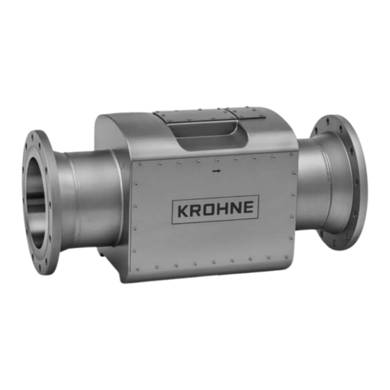
- Page 112 Calculated value Totalised flow, velocity of sound Design General The ALTOSONIC 5 flowmeter consists of a flow sensor and a signal converter. Flow sensor Construction The flow sensor has an eight-path design with a central path for optimal differentiation between turbulent, transition or laminar flow. It also includes a dedicated vertical diagnostic path for full pipe detection.
- Page 113 Low Ambient Temperature (LTA): -55…+65°C (IIB) / +60°C (IIB + H2) / - 67…+149°F (IIB) / +140°F (IIB + H2) DIV1 / ZONE1 Standard: -40…+65°C / -40…+149°F (C/US) Low Ambient Temperature (LTA): -55…+65°C / -67…+149°F Storage temperature -40…+65°C / -40…+149°F 12/2022 - 4004360704 - MA ALTOSONIC 5 en R05 www.krohne.com...
- Page 114 Carbon steel ASTM A105 / A350 Gr.LF2 Stainless steel AISI 316 / 316 L (1.4404) (dual certified) Other materials on request Converter housing Standard: Copper free aluminum Option: Stainless steel 316 (1.4408) for offshore applications www.krohne.com 12/2022 - 4004360704 - MA ALTOSONIC 5 en R05...
- Page 115 TECHNICAL DATA ALTOSONIC 5 Coating flow sensor Standard: KROHNE 1 layer paint system in accordance with ISO 12944-2:2007 Category C3 Medium / C4 Low Color: KROHNE grey (air) CNC 5252 - gloss Option: KROHNE 3 layer paint system in accordance with ISO 12944-2:2007...
- Page 116 1, 2, 3, 4, 5, 6, 8, 15, 16 codes Supported Baud rate 50, 75, 110, 150, 300, 600, 1200, 2400, 4800, 9600, 19200, 38400 (default), 56000, 64000, 115200, 128000 Baud www.krohne.com 12/2022 - 4004360704 - MA ALTOSONIC 5 en R05...
- Page 117 Signal converter 1Ex d [ia] IIB T5 Gb X, RU C- 1Ex d [ia] IIB+H2 T5 Gb X NL.AA97.B.00234/19 Display UFD 5 1Ex d IIC T6...T5 Gb X RU C- NL.AA97.B.00234/19 12/2022 - 4004360704 - MA ALTOSONIC 5 en R05 www.krohne.com...
- Page 118 2 g up to 1000 Hz OIML - R117 Flow sensor: TC 8722 Environmental classes: M2 / E2 Signal converter: TC 8548 INMETRO P_218_22_SEI_002182_22_10 SIRIM ATS 23/16 GOST NL.C.29.004.A No 64100 NUPRC E&S/SCATA/TA/521 2/98a 02.6037 www.krohne.com 12/2022 - 4004360704 - MA ALTOSONIC 5 en R05...
- Page 119 18" / DN450 1350 437.94 25.59 53.15 25.00 17.242 1892 20" / DN500 1400 482.60 27.56 55.12 27.56 19.000 2112 24" / DN600 1650 584.60 1050 32.28 64.96 32.28 23.016 2310 12/2022 - 4004360704 - MA ALTOSONIC 5 en R05 www.krohne.com...
- Page 120 18" / DN450 1300 409.34 29.53 51.18 29.53 16.116 2116 20" / DN500 1400 455.62 1250 32.28 55.12 32.28 17.938 2756 24" / DN600 1600 548.08 1910 37.01 62.99 37.01 21.578 4211 www.krohne.com 12/2022 - 4004360704 - MA ALTOSONIC 5 en R05...
- Page 121 18" / DN450 1110 428.46 29.13 53.15 27.95 16.869 2172 20" / DN500 1240 477.82 1231 31.20 55.12 30.51 18.812 2714 24" / DN600 1470 575.04 1746 36.02 64.96 36.02 22.639 3849 12/2022 - 4004360704 - MA ALTOSONIC 5 en R05 www.krohne.com...
- Page 122 [lbs] Aluminum (ATEX / 25.4 17.01 13.07 11.77 56.0 IECEx) Stainless steel 75.0 17.01 15.04 11.26 165.3 (ATEX / IECEx) Aluminum (DIV 1 / 64.0 22.92 17.01 11.50 141.1 ATEX) www.krohne.com 12/2022 - 4004360704 - MA ALTOSONIC 5 en R05...
- Page 123 10 m/s in the pipeline. However, this is not the physical limitation of the flowmeter. See for certified flowrates OIML-R117 evaluation certificate or contact KROHNE. Calculations are provided as indication, please ask KROHNE for detailed sizing. 12/2022 - 4004360704 - MA ALTOSONIC 5 en R05...
- Page 124 Engineering, commissioning, calibration, maintenance and training services Head Office KROHNE Messtechnik GmbH Ludwig-Krohne-Str. 5 47058 Duisburg (Germany) Tel.: +49 203 301 0 Fax: +49 203 301 10389 info@krohne.de The current list of all KROHNE contacts and addresses can be found at: www.krohne.com...
Need help?
Do you have a question about the ALTOSONIC 5 and is the answer not in the manual?
Questions and answers