KROHNE OPTIFLUX 5000 Handbook
Electromagnetic flowmeter in sandwich version
Hide thumbs
Also See for OPTIFLUX 5000:
- Handbook (40 pages) ,
- Quick start manual (24 pages) ,
- Supplementary instructions manual (40 pages)
Table of Contents
Advertisement
Quick Links
Advertisement
Table of Contents

Related Manuals for KROHNE OPTIFLUX 5000


Summary of Contents for KROHNE OPTIFLUX 5000
- Page 1 OPTIFLUX 5000 OPTIFLUX 5000 OPTIFLUX 5000 OPTIFLUX 5000 Handbook Handbook Handbook Handbook Electromagnetic flowmeter in sandwich version The documentation is only complete when used in combination with the relevant documentation for the converter. © KROHNE 09/2009 - 4000686201-R01-SW-en...
- Page 2 All rights reserved. It is prohibited to reproduce this documentation, or any part thereof, without the prior written authorisation of KROHNE Messtechnik GmbH & Co. KG. Subject to change without notice. Copyright 2009 by KROHNE Messtechnik GmbH & Co. KG - Ludwig-Krohne-Straße 5 - 47058 Duisburg www.krohne.com 09/2009 - 4000686201-R01-SW-en...
-
Page 3: Table Of Contents
CONTENTS OPTIFLUX 5000 1 Safety instructions 1.1 Intended use ........................5 1.2 Safety instructions from the manufacturer ..............5 1.2.1 Copyright and data protection ....................5 1.2.2 Disclaimer ..........................5 1.2.3 Product liability and warranty ....................6 1.2.4 Information concerning the documentation................6 1.2.5 Warnings and symbols used.................... - Page 4 CONTENTS OPTIFLUX 5000 5 Service 5.1 Spare parts availability....................18 5.2 Availability of services ....................18 5.3 Returning the device to the manufacturer..............18 5.3.1 General information......................18 5.3.2 Form (for copying) to accompany a returned device............19 5.4 Disposal .......................... 19 6 Technical data 6.1 Measuring principle......................
-
Page 5: Safety Instructions
SAFETY INSTRUCTIONS OPTIFLUX 5000 1.1 Intended use The flow meter measures the volumetric flow rate of electrically conductive liquids, acids, alkaline solutions, pastes and slurries, also with very high solid contents. It can be combined with an IFC 100 or an IFC 300electromagnetic signal converter. -
Page 6: Product Liability And Warranty
SAFETY INSTRUCTIONS OPTIFLUX 5000 1.2.3 Product liability and warranty The operator shall bear responsibility for the suitability of the device for the specific purpose. The manufacturer accepts no liability for the consequences of misuse by the operator. Improper installation and operation of the devices (systems) will cause the warranty to be void. The respective "Standard Terms and Conditions"... -
Page 7: Warnings And Symbols Used
SAFETY INSTRUCTIONS OPTIFLUX 5000 1.2.5 Warnings and symbols used Safety warnings are indicated by the following symbols. DANGER! This information refers to the immediate danger when working with electricity. DANGER! This warning refers to the immediate danger of burns caused by heat or hot surfaces. -
Page 8: Device Description
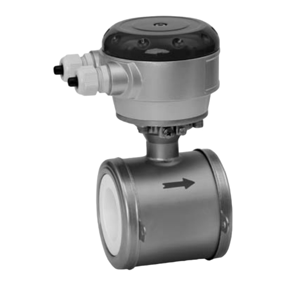
DEVICE DESCRIPTION OPTIFLUX 5000 2.1 Scope of delivery 1 Remote version 2 Compact version with IFC 300 signal converter 3 Compact version with IFC 100 (0°) signal converter 4 Compact version with IFC 100 (45°) signal converter Figure 2-1: Scope of delivery... -
Page 9: Installation
INSTALLATION OPTIFLUX 5000 3.1 Notes on installation INFORMATION! Inspect the cartons carefully for damage or signs of rough handling. Report damage to the carrier and to the local office of the manufacturer. INFORMATION! Check the packing list to check if you received completely all that you ordered. -
Page 10: Installation Conditions
INSTALLATION OPTIFLUX 5000 3.4 Installation conditions 3.4.1 Inlet and outlet Figure 3-2: Recommended inlet and outlet 1 ≥ 5 DN 2 ≥ 2 DN 3.4.2 Mounting position Figure 3-3: Mounting position www.krohne.com 09/2009 - 4000686201-R01-SW-en... -
Page 11: Flange Deviation
INSTALLATION OPTIFLUX 5000 3.4.3 Flange deviation CAUTION! Max. permissible deviation of pipe flange faces: ≤ 0.5 mm / 0.02" Figure 3-4: Flange deviation 3.4.4 T-section Figure 3-5: Distance after T-sections 1 ≥ 10 DN 3.4.5 Vibration Figure 3-6: Avoid vibrations 09/2009 - 4000686201-R01-SW-en www.krohne.com... -
Page 12: Magnetic Field
INSTALLATION OPTIFLUX 5000 3.4.6 Magnetic field Figure 3-7: Avoid magnetic fields 3.4.7 Bends Figure 3-8: Installation in bending pipes Figure 3-9: Installation in bending pipes www.krohne.com 09/2009 - 4000686201-R01-SW-en... -
Page 13: Open Discharge
INSTALLATION OPTIFLUX 5000 3.4.8 Open discharge Figure 3-10: Installation before an open discharge 3.4.9 Control valve Figure 3-11: Installation before control valve 3.4.10 Air venting Figure 3-12: Air venting 1 ≥ 5 m 2 Air ventilation point 09/2009 - 4000686201-R01-SW-en... -
Page 14: Pump
INSTALLATION OPTIFLUX 5000 3.4.11 Pump Figure 3-13: Installation after pump 3.5 Mounting 3.5.1 Torques and pressure Max. torque: • Step 1: approx. 50% of max. torque • Step 2: approx. 80% of max. torque • Step 3: 100% of max. torque given in tables... - Page 15 INSTALLATION OPTIFLUX 5000 Torques EN 1092-1 Nominal Pipe Max. allowable torque with gaskets made of size flanges Gylon Chemotherm FPM / FKM 1 EN 1092-1 Rating ftlb ftlb ftlb DN2.5...10 PN40 DN15 PN40 DN25 PN40 DN40 PN40 DN50 PN40 DN80...
-
Page 16: Electrical Connections
ELECTRICAL CONNECTIONS OPTIFLUX 5000 4.1 Safety instructions DANGER! All work on the electrical connections may only be carried out with the power disconnected. Take note of the voltage data on the nameplate! DANGER! Observe the national regulations for electrical installations! DANGER! For devices used in hazardous areas, additional safety notes apply;... -
Page 17: Virtual Reference For Ifc 300 (C, W And F Version)
ELECTRICAL CONNECTIONS OPTIFLUX 5000 4.3 Virtual reference for IFC 300 (C, W and F version) Figure 4-2: Virtual reference Possible if: Possible if: Possible if: Possible if: ≥ DN10 Electrical conductivity ≥ 200 µS/cm 09/2009 - 4000686201-R01-SW-en www.krohne.com... -
Page 18: Service
SERVICE OPTIFLUX 5000 5.1 Spare parts availability The manufacturer adheres to the basic principle that functionally adequate spare parts for each device or each important accessory part will be kept available for a period of 3 years after delivery of the last production run for the device. -
Page 19: Form (For Copying) To Accompany A Returned Device
SERVICE OPTIFLUX 5000 5.3.2 Form (for copying) to accompany a returned device Company: Address: Department: Name: Tel. no.: Fax no.: Manufacturer's order no. or serial no.: The device has been operated with the following medium: This medium is: water-hazardous toxic... -
Page 20: Technical Data
TECHNICAL DATA OPTIFLUX 5000 6.1 Measuring principle An electrically conductive fluid flows inside an electrically insulating pipe through a magnetic field. This magnetic field is generated by a current, flowing through a pair of field coils. Inside of the fluid, a voltage U is generated:... -
Page 21: Technical Data
TECHNICAL DATA OPTIFLUX 5000 6.2 Technical data INFORMATION! • The following data is provided for general applications. If you require data that is more relevant to your specific application, please contact us or your local representative. Additional information (certificates, special tools, software,...) and complete product •... - Page 22 TECHNICAL DATA OPTIFLUX 5000 Measuring accuracy Reference conditions Medium: water Temperature: 20°C / 68°F Inlet section: 10 DN Outlet section: 5 DN Flow velocity: > 1 m/s / > 3 ft/s Operating pressure: 1 bar / 14.5 psig Valve closing time variation: < 1 ms...
- Page 23 TECHNICAL DATA OPTIFLUX 5000 Pressure Pressure Pressure Pressure Ambient Atmospheric Nominal flange pressure Standard: Standard: Standard: Standard: DIN (EN 1092-1) PN16 for DN100 PN40 for DN2.5...80 Option: Option: Option: Option: PN25 for DN100 ASME B16.5 Standard: Standard: Standard: Standard: 150 lbs for ASME1/10...4"...
- Page 24 TECHNICAL DATA OPTIFLUX 5000 Installation condtitions ≥ 5 DN (without disturbing flow, after a single 90° bend) Inlet run ≥ 10 DN (after a double bend 2x 90°) ≥ 10 DN (behind a control valve) ≥ 2 DN Outlet run Dimensions and weights For detailed information see chapter "Dimensions and weights".
- Page 25 TECHNICAL DATA OPTIFLUX 5000 Approvals and certifications CE Sign This device fulfills the statutory requirements of the EC directives. The manufacturer certifies successful testing of the product by applying the CE mark. Hazardous areas Hazardous areas Hazardous areas Hazardous areas...
-
Page 26: Dimensions And Weights
TECHNICAL DATA OPTIFLUX 5000 6.3 Dimensions and weights Figure 6-1: Contruction details DN2.5...15 1 O-ring 2 Grounding ring Figure 6-2: Construction details DN25...100 1 Situation without grounding rings 2 Gasket INFORMATION! All data given in the following tables are based on standard versions of the sensor only. - Page 27 TECHNICAL DATA OPTIFLUX 5000 Nominal size Dimensions [mm] Approx. weight [kg] PN [bar] Ød1 Ød4 1 Total fitting length of flowmeter with integrated rings: Dim. L + 2 x gasket thickness. 2 Total fitting length of flowmeter without rings: Dim. L only (no gaskets required).
- Page 28 Measuring systems for sea-going tankers Head Office KROHNE Messtechnik GmbH & Co. KG Ludwig-Krohne-Str. 5 D-47058 Duisburg (Germany) Tel.:+49 (0)203 301 0 Fax:+49 (0)203 301 10389 info@krohne.de The current list of all KROHNE contacts and addresses can be found at: www.krohne.com...
Need help?
Do you have a question about the OPTIFLUX 5000 and is the answer not in the manual?
Questions and answers