Table of Contents
Advertisement
Advertisement
Table of Contents

Related Manuals for YOKOGAWA MT210


Summary of Contents for YOKOGAWA MT210
- Page 1 Digital Manometer IM 767361-01E 4th Edition...
- Page 2 Product Registration Thank you for purchasing YOKOGAWA products. YOKOGAWA provides registered users with a variety of information and services. Please allow us to serve you best by completing the product registration form accessible from our website. http://tmi.yokogawa.com/ PIM 103-04E...
-
Page 3: Foreword
Thank you for purchasing the YOKOGAWA MT200 Series* Digital Manometer. This user’s manual contains useful information about the instrument’s functions and operating procedures MT210, MT210F, and MT220, as well as precautions that should be observed during use. To ensure proper use of the instrument, please read this manual thoroughly before beginning operation. -
Page 4: Safety Precautions
If this instrument is used in a manner not specified in this manual, the protection provided by this instrument may be impaired. Also, YOKOGAWA assumes no liability for the customer’s failure to comply with these requirements. This manual is part of the product and contains important information. Store this manual in a safe place close to the instrument so that you can refer to it immediately. - Page 5 • Use the Correct Power Cord and Plug To prevent an electric shock or fire, be sure to use the power supply cord supplied by YOKOGAWA. The main power plug can only be plugged into an outlet with a protective grounding terminal. Do not invalidate this protection by using an extension cord without protective earth grounding.
- Page 6 • Utiliser le cordon d’alimentation et la fiche adaptés Pour éviter les risques de choc électrique ou d’incendie, utilisez le cordon d’alimentation fourni par YOKOGAWA. La fiche doit être branchée sur une prise secteur raccordée à la terre. En cas d’utilisation d’une rallonge, celle-ci doit être impérativement reliée à la terre. Par ailleurs, n’utilisez pas le cordon d’alimentation fourni pour cet instrument avec un autre appareil.
- Page 7 • Ne pas utiliser dans un environnement explosif Cet instrument n’est pas antidéflagrant. Ne pas utiliser l’instrument en présence de gaz ou de vapeurs inflammables. Cela pourrait être extrêmement dangereux. • Ne pas retirer le capot, ni démonter ou modifier l’instrument Seul le personnel YOKOGAWA qualifié est habilité à retirer le capot et à démonter ou modifier l’instrument. Certains composants à l’intérieur de l’instrument sont à haute tension et par conséquent, représentent un danger. • Mesure du fluide haute pression • Utiliser une tuyauterie et des connecteurs pression pouvant résister à...
-
Page 8: Symbols Used In This Manual
3000 kPa) (includes DMM and 24 VDC output functions) 767357 (MT220) Absolute pressure ( 130 kPa abs) (includes DMM and 24 VDC output functions) 767361 (MT210) Gauge pressure 10 kPa) 767363 (MT210) Gauge pressure 130 kPa) 767365 (MT210) Gauge pressure... - Page 9 Safety Precautions SUFFIX (Suffix Code) Name Suffix Code Description Units of pressure kPa only kPa, switchable to kgf/cm , mmH O, and mmHg kPa, switchable to kgf/cm , mmH O, mmHg, inH O, inHg, and psi Communication GP-IB Interface interface RS-232 Interface Input connection Rc 1/4 1/4 NPT female-threaded...
- Page 10 Safety Precautions Optional Accessories The following optional accessories are also available. Upon receipt of any optional accessories, make sure that no items are missing or damaged. Part Name Model/Part No. Minimum Purchase Quantity Battery pack Seal, screws (M5 × 40 mm × 4) 269913 Ni-Cd batteries 269914...
-
Page 11: Compliance With The Radio Waves Act (Republic Of Korea)
Registration No: KCC-REM-IMY-ERA010 Equipment Name: DIGITAL MANOMETER Trade Name: Yokogawa Test & Measurement Corporation Manufacturer: Yokogawa Test & Measurement Corporation Emission This is a Class A product. Operation of this product in a residential area may cause radio interference in which case the user is required to correct the interference. -
Page 12: Table Of Contents
Contents Foreword ..........................1 Safety Precautions Symbols Used in this Manual ...................6 Checking the Contents of the Package ................6 Compliance with the Radio Waves Act (Republic of Korea) ..........9 Name and Functions of Each Part System Block Diagram ....................12 Functions ........................14 Front Panel ........................16 Rear Panel ........................18 Side View ........................19... - Page 13 Contents Turning GP-IB ON/OFF....................51 Interface Messages Supported by the Instrument ............52 Switching between Remote and Local Mode ..............52 Setting the Mode and Address ..................52 Setting the GP-IB Interface ....................53 Overview of the RS-232 Interface RS-232 Interface Functions ...................54 RS-232 Interface Specifications ..................54 Connecting the RS-232 Interface Cable ................54 Connector and Signal Names ..................55 Signal Direction ......................55...
-
Page 14: Name And Functions Of Each Part
System Block Diagram The fluid pressure to be measured is sent to the resonant sensor section. The resonant sensor section consists of a resonant sensor (developed by YOKOGAWA) and an excitation circuit to convert the fluid pressure to a frequency signal. The frequency signal is then sampled in the pressure sensor section at the rate corresponding to the current measurement mode and converted into a pressure value. As necessary, the converted pressure value undergoes processing such as averaging, and is then sent to the main CPU and displayed. - Page 15 Name and Functions of Each Part Power Supply and Power Switch This instrument can be operated from three different kinds of power supply, commercial power, DC power (10 to 15 VDC), and battery pack (optional). To operate the instrument using commercial power, turn ON both the MAIN POEWR switch (rear panel) and POWER switch (front panel). In most cases, you should always leave the MAIN POWER switch ON, and turn the power ON or OFF using the POWER switch only.
-
Page 16: Functions
Name and Functions of Each Part Functions Functions Common to the MT210, MT210F, and MT220 • Pressure Measurement (Gas and Liquid) Measured values are displayed in 5-1/2 digits. They can also be displayed in 4-1/2 digits (the lowest digit is masked). However, with the 700 kPa model (767355, 767365, 767373, and 767385), measured values are displayed only in 4-1/2 digits (or 3-1/2 digits when the lowest digit is masked). - Page 17 Name and Functions of Each Part MT210F Only • Three Measurement Modes With the three measurement modes (normal, medium-speed, and high- speed), you can perform highly precise pressure measurements with rapid response. • Dynamic Mode (/DA option Only) When dynamic mode is ON, you can achieve D/A output with fast response regardless of the measurement mode.
-
Page 18: Front Panel
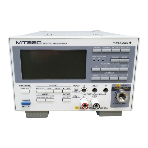
Name and Functions of Each Part Front Panel The front panels of the MT210, MT210F, and MT220 are shown in the figures below. The MT210 and MT210F have the same key layouts. MT210F (not MT210) is displayed in the upper left of the MT210F. MT210 Differential Pressure Model MT210/MT210F Absolute Pressure/Gauge Pressure Model... - Page 19 Name and Functions of Each Part PARAMETER SET keys Selects parameters to be set, and increments the active (blinking) digit. Selects parameters to be set, and decrements the active (blinking) digit. Changes the active digit. ENTER/ Enters the selected values. LOCAL Clears remote mode.
-
Page 20: Rear Panel
Name and Functions of Each Part Rear Panel The rear panels of the MT210, MT210F, and MT220 are shown in the figures below. The MT210F/MT220 differential pressure model is not shown. Absolute Pressure and Gauge Pressure Models (MT210/MT210F/MT220) OUTPUT DC POWER WARNING SUPPLY GPIB (IEEE488) Do not operate without reading safety precaution in user s manual. 10-15V DC 10VA MAX MAIN POWER... -
Page 21: Side View
Name and Functions of Each Part Rear Panel MAIN POWER switch Turns commercial power ON and OFF. Turning this switch OFF shuts off the primary side of the power supply circuit. Turn this switch ON while the batteries are charging. Power connector A 3-prong connector with a protective grounding terminal. -
Page 22: Before Starting Measurement
Some parts of the instrument carry high voltages and are extremely dangerous. When the instrument needs internal inspection or adjustment, contact your dealer or nearest YOKOGAWA representative as listed on the back cover of this manual. • If you notice smoke or unusual odors coming from the instrument, turn both the POWER and MAIN POWER switches OFF and unplug the power cord immediately. -
Page 23: Operating Conditions
Before Starting Measurement Operating Conditions The instrument must be used in a place where the following conditions are met. Ambient Temperature and Humidity • Ambient temperature: 5 to 40°C (10 to 35°C for the 767370). To ensure high measurement accuracy, the ambient temperature should be 23 ± 3°C. -
Page 24: Supplying Ac Power
OFF. • Pour éviter tout risque de choc électrique ou d’incendie, utiliser exclusivement le cordon d’alimentation fourni par YOKOGAWA et prévu pour l’instrument. • Relier l’instrument à la terre pour éviter tout risque de choc électrique. -
Page 25: Supplying Dc Power
Before Starting Measurement Power Rating Rated supply voltage range : 100 to 120 VAC/220 to 240 VAC Permitted supply voltage range : 90 to 132 VAC/180 to 264 VAC Rated supply voltage frequency : 50/60 Hz Permitted supply voltage frequency range : 47 to 63 Hz Power consumption (pressure measurement only) : 25 VA MAX (100 VAC) : 40 VA MAX (200 VAC) -
Page 26: Turning The Power Switch On/Off
Before Starting Measurement French AVERTISSEMENT • Afin d’éviter tout risque de choc électrique, utilisez une alimentation électrique ne dépassant pas 60 VDC. ATTENTION • Ne mettez jamais les bornes en court-circuit. • L’application à l’instrument d’une tension c.c. dépassant la plage de tension d’alimentation permise peut provoquer des dommages. •... - Page 27 OFF. If the batteries appear to be running out, they need to be replaced immediately. The batteries cannot be replaced by the user. Contact your nearest YOKOGAWA representative as listed on the back cover of this manual.
-
Page 28: Opening Messages
Before Starting Measurement Opening Messages Power Switch ON All Segments Lit Model Number Suffix Code (Units of Pressure, Communications Functions) Model Number Version With the GP-IB interface in With the GP-IB interface in addressable mode talk-only mode When starting up with the GP-IB and battery pack, or using DC power With the RS-232 interface in With the RS-232 interface in normal mode... -
Page 29: Default Settings (On Shipment From The Factory)
Before Starting Measurement Default Settings (On Shipment from the Factory) Item Default (Factory Setting) Backup Functions Common to the MT210, MT210F, and MT220 Pressure zero calibration value Units of pressure Number of display digits 5-1/2 Relative display Data hold Pressure averaging... -
Page 30: Pressure Measurement
Pressure Measurement Zero Calibration Zero calibration refers to corrections made to compensate for effects caused by changes in temperature and the installation environment, in order to perform measurement with high accuracy. Before starting measurement, make sure that zero calibration (ZERO CAL) has been performed. Furthermore, if operating conditions are likely to change, perform zero calibration again periodically. -
Page 31: Input Function
Pressure Measurement • When working with absolute pressure models, zero calibration is very complex, so use the relative function to correct errors if the operating position differs from that in which zero calibration was performed. • In the case of the absolute pressure model, zero calibration values cannot be changed by initializing setup information using the RC communications command or the ENTER/LOCAL after the power switch is turned ON. - Page 32 Pressure Measurement French ATTENTION • N’appliquez jamais au port d’entrée une pression dépassant la pression d’entrée autorisée, sinon cela pourrait endommager l’instrument. La plage de pression d’entrée autorisée est indiquée ci-dessous. Modèle Plage de pression d’entrée autorisée Affichage 767351 2,7 kPa abs à 500 kPa jauge –12,0000 à...
- Page 33 • If cleaning of the inside of the instrument is necessary, contact your nearest YOKOGAWA representative as listed on the back cover of this manual. When Using the 1 kPa Model (767370), or the 10 kPa Model (7673 1)
-
Page 34: Selecting The Units
Pressure Measurement Selecting the Units Select the units of pressure using the UNIT key. For -U1 models Pressing the UNIT does not change the units. For -U2 models Pressing the UNIT switches the units in the order kPa, kgf/cm , mmH O, mmHg, kPa. -
Page 35: Turning The Back Lighting On/Off
Pressure Measurement Turning the Back Lighting ON/OFF You can turn on a back light for the screen. The back light makes it easier to see the screen when you are working in a dark area. However, the life of the batteries will be shortened if the instrument is running on them while the back light is ON. -
Page 36: D/A Output (/Da Option)
Pressure Measurement • Other than 767360 Mesurement Mode Pressure Averaging Minumum Trigger Input Interval MT210/MT210F MT220 DMM OFF DMM ON DMM Averaging 1.6 s 2.5 s 1.6 s Normal 1.6 s 500 ms 260 ms 500 ms 2.5 s Medium-speed... - Page 37 Pressure Measurement • The relationship between the display update and the output voltage. Response time D/A output response time Actual Pressure Change in dynamic mode Pressure D/A Output Voltage Change Display Update Dynamic mode (MT210F only) Time Display update rate Press MENU.
-
Page 38: Comparator Function (/Da Option)
Pressure Measurement Comparator Function (/DA Option) Determines whether the measured pressure data is greater than or less than two reference values (Hi and Lo) and displays the results on the front panel LED. Also, the determined results are output as a TTL from the output connector on the rear panel. -
Page 39: Setting The Measurement Mode
Pressure Measurement Setting the Measurement Mode • For the MT210 Press MENU. , and press ENTER/LOCAL. Use the to set Use the to set the pressure sample rate ( ) and press ENTER/ LOCAL (767370 only). : 250 ms : 4000 ms... -
Page 40: Output Connector (/Da Option)
Pressure Measurement Output Connector (/DA Option) • Pin assignment • Input/output circuit +5 V +5 V 10 kΩ 100 Ω EXT TRIG Hi, In, Lo, Busy 100 Ω TTL Level TTL Level L : 0 to 0.4 V L : 0 to 0.4 V H : 2.4 to 5 V H : 2.4 to 5 V •... -
Page 41: Adjusting And Calibrating The Differential Pressure Transmitter Using The Mt220
Adjusting and Calibrating the Differential Pressure Transmitter using the MT220 Connecting the Differential Pressure Transmitter to the MT220 To measure output from the differential pressure transmitter in terms of current, connect the transmitter to the instrument and calibrate the transmitter. MT 220 differential output pressure transmitter terminal current input terminal WARNING Including the internal electric potential, the maximum allowable potential difference for all input/output and ground terminals is 42 Vpeak. Ensure that the potential of each terminal does not exceed the following values. -
Page 42: Vdc Ouput
Adjusting and Calibrating the Differential Pressure Transmitter using the MT220 French AVERTISSEMENT Y compris le potentiel électrique interne, la différence de potentiel maximum autorisée pour tous les bornes d’entrée/sortie et de terre est de 42 V crête. Assurez-vous que le potentiel de chaque borne ne dépasse pas les valeurs suivantes. Si cette valeur est dépassée, cela peut endommager l’instrument ou des blessures corporelles. -
Page 43: Dmm Function
Adjusting and Calibrating the Differential Pressure Transmitter using the MT220 DMM Function If nothing is displayed in the lower part of the screen, press the ON/OFF under the DMM group to turn the DMM function ON. Press DC5 V/20 mA to set the mark to either V or mA. To cancel DMM measurement, press the ON/OFF under the DMM group again to turn the DMM function OFF. -
Page 44: Error Display
Adjusting and Calibrating the Differential Pressure Transmitter using the MT220 Setting 0% and 100% by Applying Actual Pressure (Automatic Setting) Apply pressure which corresponds to 0%. Press the Auto %. Apply pressure which corresponds to 100%. Press the Auto 100%. Press the %ERROR key to activate % display mode. Note • Any 0% and 100% pressure values can be set as long as they are within the display range and satisfy the condition 0% value < 100% value. • If the applied pressure is outside the display range, it can be set as the 0% or 100% value even if the AUTO 0% or AUTO 100% has been pressed. -
Page 45: Storing And Recalling Data (Mt220 Only)
Storing and Recalling Data (MT220 Only) Storing Data Acquired data is assigned a specific memory number and then stored in the internal memory. 1 to 9999 can be set as the data number (memory number). If no destination memory number is specified, data will be stored under consecutive memory numbers (default starting number is 1). When a memory number is specified, data is saved successively starting with that number. Two types of storage methods are available, auto store and manual store. Data acquisition interval (number of samples taken per stored data item): 1, 4, 16, 64, 512... -
Page 46: Manual Store
Storing and Recalling Data (MT220 Only) Manual Store Pressing the STORE key stores data. If no destination memory number is specified, the data is stored under the memory number immediately following the one in which the last data item was stored. Making Manual Store Settings Press MENU. Keep pressing until is displayed in the screen, then press ENTER/LOCAL to proceed to the store mode setting screen. -
Page 47: Deleting Data
Storing and Recalling Data (MT220 Only) Recalling Data by Specifying the Corresponding Memory Number Press No. while recall mode is active. , or to select the desired memory number. Press ENTER/LOCAL to recall the data. To cancel recall mode, press RECALL again. RECALL disappears from the screen. -
Page 48: Battery Pack (Optional)
Battery Pack (Optional) Connecting the Battery Pack to the Main Unit WARNING • Before attaching the battery pack to the instrument, be sure to turn OFF the POWER switch (on the front panel) then the MAIN POWER switch (on the rear panel), and remove the power cord from the AC outlet. •... -
Page 49: Charging The Ni-Cd Batteries
Hold down the BATTERY CHECK. The red LED lights up and the remaining life of the battery pack is indicated as follows. Two LEDs are lit. Approximately 6 to 10 hours (MT210 + battery pack) One LED is lit. Approximately 3 to 6 hours (MT210 + battery pack) No LEDs are lit. - Page 50 Battery Pack (Optional) CAUTION • When charging, make sure that the instrument is in the horizontal or vertical position, or that it is leaning on its stand. To prevent overheating, do not lean the instrument on its side. Also, allow the unit to dissipate heat by keeping the area around it clear of any objects.
-
Page 51: Replacing The Ni-Cd Batteries
(front panel) then the MAIN POWER switch (rear panel), and remove the power cord from the AC outlet, since there is the possibility of an accident or short-circuit in the charging circuit. • Use only Ni-Cd batteries manufactured by YOKOGAWA (Model 269914). French AVERTISSEMENT •... - Page 52 Battery Pack (Optional) Turn OFF the POWER switch, then the MAIN POWER switch. Remove the power cord from the AC outlet. Unfasten the four screws (M3 × 5 mm) indicated in the diagram below and remove the cover. Unplug the connector (see figure next page). Do not pull on the connector cable. All three Ni-Cd batteries must be replaced together.
-
Page 53: Overview Of The Gp-Ib Interface
Overview of the GP-IB Interface GP-IB Interface Function Listener It is possible to enter the same settings via the GP-IB interface that can be made using the front panel keys. Measured or computed data, panel setup information, and error codes can be received. -
Page 54: Interface Messages Supported By The Instrument
Overview of the GP-IB Interface Interface Messages Supported by the Instrument • IFC (Interface Clear) Cancels (unaddresses) talker and listener. • REN (Remote Enable) Transfers the instrument from local control to remote control. • GTL (Go To Local) Transfers the instrument from remote control to local control. •... -
Page 55: Setting The Gp-Ib Interface
Overview of the GP-IB Interface Address Setting Range 0–30 The factory setting is 1. Talk-Only Function This function only allows the instrument to send measured or computed data to other devices. Even if the instrument is not assigned as a talk-only device, it can still send data. -
Page 56: Overview Of The Rs-232 Interface
Overview of the RS-232 Interface RS-232 Interface Functions Receiving Function It is possible to enter the same settings via the RS-232 interface as can be entered using the front panel keys. Measured or computed data, panel setup information, and error codes can be received. -
Page 57: Connector And Signal Names
Overview of the RS-232 Interface Connector and Signal Names Pins 14–25 unused Pin 6 Pins 8–13 unused unused RS-232 connector: DBSP-JB25S equivalent The figure above shows the pin numbers on the RS-232 connector. 1 AA (GND: Protective Ground) : Grounded to the case of this instrument. 2 BA (TXD: Transmitted Data) : Data transmitted to a personal computer. Signal direction .. -
Page 58: Table Of Rs-232 Standard Signals And Their Jis And Ccitt Abbreviations
Overview of the RS-232 Interface Table of RS-232 Standard Signals and Their JIS and CCITT Abbreviations Table of Signals Pin Number Abbreviation Name (25-pin connector) RS-232 CCITT AA (GND) Protective ground AB (GND) Signal ground BA (TXD) Transmitted data BB(RXD) Received data CA(RTS) Request to send... -
Page 59: Description Of Each Handshaking Method
Overview of the RS-232 Interface Description of Each Handshaking Method OFF-OFF • Data Sending Control Handshaking is not carried out between the instrument and the PC. X-on and X-off messages from the PC are treated as data, and CB(CTS) is ignored. • Data Receiving Control Handshaking is not carried out between the instrument and the PC. After the instrument’s receive buffer becomes FULL, excess data is discarded. -
Page 60: Precautions Regarding Data Receiving Control
Overview of the RS-232 Interface Precautions Regarding Data Receiving Control When handshaking is used to control the reception of data, data may still be sent from the computer even if the free space in the receive buffer drops below 64 bytes. In this case, after the receive buffer becomes full, the excess data will be lost whether handshaking is in effect or not. Data storage to the buffer will begin again when there is free space in the buffer. When handshaking is in use, the transfer of data from the 256 Bytes buffer to the internal program cannot keep up with the transmission, so the reception... -
Page 61: Rs-232 Communications Settings
Overview of the RS-232 Interface RS-232 Communications Settings Use the settings below to setup communications so that you can enter settings on the instrument using the PC, or output setting information or values to the computer. • Selecting the Handshaking Method Choose a data sending/receiving control from the following: Settings Handshaking Method... -
Page 62: Setting The Handshaking Mode, Data Format, And Baud Rate
Overview of the RS-232 Interface Setting the Handshaking Mode, Data Format, and Baud Rate With the handshake mode setting screen ( ) displayed, press set the value corresponding to the desired mode, then press ENTER/LOCAL. For a description of the settings, refer to the table given on the previous page. With the data format setting screen ( ) displayed, press to set the... -
Page 63: Before Programming
Before Programming Basic Programming Format The following shows the structure of program data. Command + Parameter + Terminator ASCII codes are used. Example CRLF Command Parameter Terminator Command Predefined string of 1 to 3 capital letters Parameter Numeric values or character string (ASCII code) Terminator GP-IB interface Specify CR+LF, LF, or EOI for the receive terminator. -
Page 64: Troubleshooting, Maintenance, And Inspection
If the instrument does not operate properly even if the actions given in the table below are performed, or if Service required is stated as a corrective action, or if there are any other problems, contact YOKOGAWA or your YOKOGAWA sales representative. -
Page 65: Self-Test Error When The Power Is Turned On
Troubleshooting, Maintenance, and Inspection No. Type of Error Cause Corrective Action Page Store error Internal memory full Delete unneeded measurement data. 36 to 38 Store error Attempted to store measurement data Delete the existing data, or use an zunder an already existing data number. unused data number. -
Page 66: Calibrating The Pressure Measurement Function
Calibration and adjustment of the accuracy can be performed at YOKOGAWA. Calibration and adjustment of the accuracy requires a high level of skill, so contact your nearest YOKOGAWA representative as listed on the back cover of this manual. Calibrating the DMM Function (MT220 Only) - Page 67 Troubleshooting, Maintenance, and Inspection Connection Method Connect each instrument as shown below. For voltage calibration For current calibration MT220 MT220 DC voltage DC voltage current current 2794 generator generator Digital Digital multi-meter multi-meter * Do not make any connections to the * Do not make any connections to the current terminal of the MT220.
-
Page 68: Recommended Replacement Parts
Recommended Replacement Parts We recommend periodic replacement so that you will be able to use the MT210/ MT210F/MT220 for a long period of time. Contact your nearest YOKOGAWA dealer for replacement parts. -
Page 69: Fuse Position And Replacement Method
A1429EF Power supply board Service required* *: Professional service is required. Contact your nearest YOKOGAWA representative as listed on the back cover of this manual. Fuse Position and Replacement Method Turn the fuse holder to the left and pull out the fuse holder. Then, replace with a new fuse. -
Page 70: Specifications
767363/767383: approx. 6.5 kg 767355: approx. 8.5 kg/ 767365: approx. 8 kg *1 Operating conditions: Temperature 23 ± 3°C, humidity 20 to 80% RH, power voltage rating ±5%, positioned horizontally. Refer to Yokogawa’s pressure standard. *2 Measurement mode can be switched between normal, medium-speed, and high-speed on the 76738 only. *3 Data output rate via communications is the same as the display update rate. -
Page 71: Pressure Measurement Section (767356/767366/767386/767357/767367/767387)
767366/767386: approx. 6.5 kg 767367/767387: approx. 6.5 kg *1 Operating conditions: Temperature 23 ± 3°C, humidity 20 to 80% RH, power voltage rating ±5%, positioned horizontally. Refer to Yokogawa’s pressure standard. *2 Measurement mode can be switched between normal, medium-speed, and high-speed on the 76738 only. *3 Data output rate via communications is the same as the display update rate. -
Page 72: Pressure Measurement Section (767370/767371)
Weight (Main unit) Approx. 8.2 kg. Approx. 289 oz. Approx. 8.2 kg. Approx. 289 oz. *1 Operating conditions: Temperature 23 ± 3°C, humidity 20 to 80% RH, power voltage rating ±5%, positioned horizontally. Averaging is OFF for the 767370 and ON for the 767371. Refer to Yokogawa’s pressure standard. *2 The difference between L and H is less than 50 kPa Pressure Measurement Section (767372/767373) Model Code 767372... -
Page 73: Pressure Measurement Section (Common To All Models)
Specifications Pressure Measurement Section (Common to All Models) Leakage Less than 10 –5 /sec Permissible Fluids Non-flammable, non-explosive, non-toxic, or non-corrosive gasses and liquids Fluid Temperature 5 to 50°C –6 Fluid Viscosity Less than 5 × 10 Pressure Sensor Silicon resonant sensor Pressure Sensing Element Diaphragm Display Units kPa only, kPa (kgf/cm , mmHg, mmH O), or kPa (psi, inHg, inH... -
Page 74: Communication Function (Install Either One)
Specifications Communication Function (install either one) • GP-IB Interface Electrical and mechanical Conforms to IEEE St’d 488-1978 specifications Functional specifications SH1, AH1, T5, L4, SR1, RL1, PP0, DC1, DT1, and C0 • RS-232 Interface Synchronization Start-stop synchronization Baud rate 1200, 2400, 4800, or 9600 bits/s Option /DA • D/A Output Specifications Output voltage 0 to ±2 V or 0 to ±5 V (switchable) Output example: 130 kPa gauge pressure model Output range when ±2 V 0 kPa: 0 V... -
Page 75: Common Specifications
10 to 15 VDC Permitted DC Voltage Range 9 to 16.5 VDC Battery Pack External Ni-Cd batteries: For the MT210/MT210F (Optional Accessory) The instrument can be operated continuously for approximately 10 hours (with back light on) if the batteries have been charged fully. -
Page 76: External Dimensions
Specifications External Dimensions Unit: mm Rear Panel (With RS-232 Connector) (With GP-IB Connector) MT210/MT210F Absolute Pressure/Gauge Pressure MT210 Differential Pressure MT220 Absolute Pressure/Gauge Pressure DIGITAL MANOMETER LIGHT % Error AUTO 0% AUTO 100% COMP DIGITS MENU IN LO PARAMETER SET... -
Page 77: Appendix
A detailed description of each command is provided in these appendixes. Command Description Notes Functions Common to the MT210, the MT210F, and the MT220 Pressure zero calibration Setting the Units Sets the number of pressure display digits (4-1/2 or 5-1/2) -
Page 78: Communications Command List
“m” represents ON/OFF for the averaging the relative value. An error 15 occurs. function. • Cannot execute in recall mode. An For the MT210/MT210F error 14 occurs. 0: Averaging is OFF for pressure measurement. 1: Averaging is ON for pressure Sets the current measured pressure value as measurement. - Page 79 Appendix Query CAP/CAP? BP?<terminator> Sets the calibration points for the DC current (20 Response Example mA range), and queries the current setting. Syntax for setting CAPm<terminator> “m” represents the calibration point. Sets the value of the DC current in the 0: After calibration, the correction calibration point and queries the measurement coefficient is calculated, then the result is...
- Page 80 Appendix CVP/CVP? Description • Only valid with the D/A output option (/ Sets the calibration points for the DC voltage (5 V range), and queries the current setting. • The parameters are set in the order Syntax lower limit, then upper limit. The CVPm<terminator>...
- Page 81 Appendix Syntax Syntax DB m, n <terminator> DIS m <terminator> “m” represents the Number of the first “m” represents the display mode. memory location to be deleted. 0: Normal measurement display m=1 to 9999 1: % display “n” represents the number of the last 2: %ERROR display (possible only when memory location to be deleted. the DMM function is ON) n=1 to 9999 (n≥m) Query Query...
- Page 82 Sets the criteria for a status byte interrupt and • Only valid with the D/A output option (/ queries the current setting. DA) on the MT210F. Syntax • On the MT210/MT210F, it is fixed to IMm<terminator> OFF(DY0)It cannot be set to ON(DY1). “m” is the cause for the interrupt, (0 to 31).
- Page 83 Description Query • Measurement mode changes can only MHm? <terminator> be made on the MT210F. Response Example • On the MT210/MT220, the mode is MH4, 130.000 fixed at (MS0). Middle-speed (MS1) Description and high-speed (MS2) cannot be “m” in the query syntax also represents selected.
- Page 84 Appendix PD/PD? Requests output of the number of data items it Sets the number of display digits for the is possible to store. measured pressure value and the value to be Syntax displayed in %, and queries the current setting. OM <terminator> Syntax Response Example PDm<terminator> FREE2000 <terminator> “m” represents the number of display digits.
- Page 85 Appendix Description Description • The available settings vary depending • When an overrange occurred in the on the pressure units specification code measured pressure value (and “--OL- you selected at the time of purchase. -” was displayed), the relative display • The units cannot be changed when in could not be turned ON.
- Page 86 Appendix SNO/SNO? Response Example Sets the store destination memory number/ Description queries the current setting. • The sampling rate can only be changed Syntax on the 767370 (1 kPa differential SNO m <terminator> model). “m” represents the store destination This setting is not available on other memory Number models.
- Page 87 Appendix SO/SO? Description Sets whether to start or stop data storage in • DMM calibration mode cannot be set if auto store mode/queries the current setting. the DMM function is OFF. An error 16 Syntax occurs. SO m <terminator> • DMM calibration mode cannot be set “m”...
-
Page 88: Status Byte Format
Appendix Status Byte Format GP-IB (Response to the Serial Poll) DI08 DI07 DI06 DI05 DI04 DI03 DI02 DI01 24 VOUT Syntax Auto Calcula- ERROR OVER store tion (fixed) -OL- Error SRQ (DIO 7) This bit is set to 1 when a computation END, syntax ERROR, or OVER occurs, and SRQ is set to True, thereby issuing a service request to the controller. -
Page 89: Data Output Format
Appendix RS-232 (Response to the <ESC>S Command) DI08 DI07 DI06 DI05 DI04 DI03 DI02 DI01 24 VOUT Syntax Auto Calcula- ERROR OVER store tion (fixed) (fixed) -OL- Error For DIO1 to DIO6, the status byte format is identical to that used for the GP-IB interface. - Page 90 Data state when there is no data (“ ” is displayed.) h1 h2 h3 Data state on the DMM side when the DMM function is off h1 h2 h3 Output Format For the MT210/MT210F Terminator Pressure header Pressure data Output Examples KPAN 130.000 For the MT220 Pressure header Pressure data...
-
Page 91: Output Format Of Setup Information (Response To The "Os" Command)
• No recall data NO.E0002, KPAE 888888., V 888888. Output Format of Setup Information (Response to the “OS” Command) For the MT210/MT210F 1st line: Model, software version number. 2nd line: Pressure setup information 3rd line: Measurement condition 4th line: Backlight and beep... -
Page 92: Sample Program
Appendix Example of response MDL767303;REV1.01 REL0;PU4;PD0;ML4,0.000;MH4,130.000 DMM1;DF1 HD0;AG3;DIS0 VO0L;BL0;BP1 SM0;SN01;SR0;SND20 DR0;CMP0;CMD0.000,130.000 Sample Program Operating Environment Target model: NEC PC-9801 Series Target language: N88-BASIC (standard program language on the PC-9801 Series) GP-IB board: PC-9801-29N interface board ‘************************************************************************* ‘* Program that reads/displays the measured data 10 times (GP-IB)’ ‘************************************************************************* ‘... - Page 93 Appendix 490 ‘ 500 IRESET REN ‘cancel remote 510 STOP ‘exit 520 END ‘************************************************************************* ‘* Program that reads/displays the measured data 10 times (RS-232) ‘************************************************************************* ‘ 100 OPEN “COM:N81NN” AS #1 ‘open line 110 PRINT #1,CHR$(&H1B)+”R” ‘set remote 120 ‘ 130 PRINT #1,”PU4”...
- Page 94 Appendix 180 GOSUB *CHECKSYNTAX ‘error check 190 ‘ 200 *CAL1 PRINT @IO;”CVP1” ‘calibration point = 0 PRINT “Set standard equipment output to 0 V.”” INPUT “Press Return. “,K$ 240 PRINT @IO;”CVD0” : INPUT WAIT 30,” “,A’calibration point value = 0.00000 (fixed) GOSUB *CHECKSYNTAX ‘error check LINE INPUT @1;D$ : E$=MID$(D$,5,8) ‘read measured value PRINT “The current measured value is “;E$;”...
-
Page 95: Index
Index Symbol Page Page % Display............41 GP-IB interface %ERROR display ..........42 Listener ..............51 Remote mode ............52 24 VDC Ouput ...........40 Response to the serial poll ......App-12 Page Specifications ............51 Accessories ............7 Status byte format ..........App-12 Addressable mode..........52 Talker ..............51 Auto % ...............42 Talk-only function ........... - Page 96 Index Page Sample program ........App-16 Selecting the number of display digits ....32 Selecting the units ..........32 Self-test .............25 Specifications ............68 Standard accessories ..........7 Storing Data............43 SUFFIX ..............7 Suffix code ............7 Supplying AC Power ..........22 Supplying DC Power .........23 System Block Diagram ........12 Page Talk-Only Mode..........52 Terminator............61...
Need help?
Do you have a question about the MT210 and is the answer not in the manual?
Questions and answers