
Subscribe to Our Youtube Channel
Related Manuals for YOKOGAWA VigilantPlant mR20000


Summary of Contents for YOKOGAWA VigilantPlant mR20000
- Page 1 Operation Guide Models 437101/437102/437103/437104/ 437106/437112/437118/437124 µR20000 Recorder 4 P 2 B 1 0 2 E 0 2 IM 04P02B01-02E 2nd Edition Yokogawa Electric Corporation...
-
Page 2: Table Of Contents
Contents Foreword .................................. 3 Safety Precautions ..............................3 Handling Precautions ............................... 4 How to Use This Manual ............................4 Checking the Contents of the Package ........................5 Removing the Packing Materials ..........................6 Recorder’s Version and Functions Described in This Manual .................. 7 Function Introduction/Names of Parts ........................ -
Page 3: Foreword
However, should you have Protective ground terminal any questions or find any errors, please contact your nearest YOKOGAWA dealer as listed on the back cover of this manual. • Copying or reproducing all or any part of the contents of this manual without the permission of Yokogawa Electric Corporation is strictly prohibited. -
Page 4: Handling Precautions
Ensure that the source voltage matches the voltage of the separately. power supply before turning ON the power. • YOKOGAWA assumes no liability to any party for any loss or • Protective Grounding damage, direct or indirect, caused by the user or any Make sure to connect the protective grounding to prevent unpredictable defect of the product. -
Page 5: Checking The Contents Of The Package
Checking the Contents of the Package Standard Accessories Z-fold chart Plotter pen Ribbon Disposable Unpack the box and check the contents before operating the paper felt pen cassette instrument. If some of the contents are not correct or missing or if there is physical damage, contact the dealer from which you h a r d in... -
Page 6: Removing The Packing Materials
Optional Accessories (Sold Separately) Removing the Packing Materials The optional accessories below are available for purchase Open the door, hold the left and right tabs and pull the display and separately. If you make an order, make sure that all contents are key panel section toward you. -
Page 7: Recorder's Version And Functions Described In This Manual
Recorder’s Version and Functions Described in This Manual The contents of this manual corresponds to the recorder with version 1.31. µR20000 Versions and Functions Version Suffix Code Added or Modified Functions Reference 1.11 or earlier – – – 1.21 (Added) Language support (German and French) Sec. -
Page 8: Function Introduction/Names Of Parts
Function Introduction/Names of Parts Function Introduction The µR20000 Recorder (hereafter referred to as the recorder) can be used to assign DC voltage, 1-5V, thermocouple, RTD, and contact or voltage ON/OFF signal to channels for measurement. The measured results are recorded with pens or dots on a chart paper that is fed at a constant speed. -
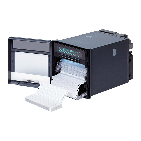
Page 9: Names Of Parts
Function Introduction/Names of Parts Names of Parts Front Display and key panel Door Hold the left and right tabs and pull to open. Mounting hole There is one hole on each of the top, bottom, left, and right panels. The hole is covered with a seal. Power switch Turns ON/OFF the power each Chart cassette... -
Page 10: Display And Key Panel
Function Introduction/Names of Parts Display and Key Panel Status display Displays the following information. RECORD.... Illuminates while recording measured values. KEY LOCK..Illuminates when key lock is enabled. MATH....Illuminates when computation on the computation function (/M1 option) is in progress. CHART END.. -
Page 11: Installing/Wiring The Recorder
Installing/Wiring the Recorder Installation Location Install the recorder indoors in a location that meets the following conditions. • Instrument Panel The recorder is designed for panel mounting. The portable type (/H5x option) is designed to be used on the desktop. •... - Page 12 Installing/Wiring the Recorder • Mount the recorder to the panel according to the procedure below. • First, attach the two mounting brackets and temporarily fasten the attachment screws. • Next, fix the recorder in place by tightening the attachment screws with the appropriate torque.
- Page 13 Installing/Wiring the Recorder Panel Cutout 360 MIN (14.17) 361 MIN (14.21) (11.06) Unit: mm (approx. inch) Unless otherwise specified, tolerance is ±3% (however, tolerance is ±0.3 mm when below 10 mm). (11.06) External Dimensions of the Portable Type (/H5x Option) Unit: mm (approx.
-
Page 14: Input Signal Wiring
Installing/Wiring the Recorder Input Signal Wiring WARNING • To prevent electric shock while wiring, ensure that the power supply source is turned OFF. CAUTION • The input terminals of this instrument are specific to this instrument. Do not connect the input terminals of the µR1000, µR1800 or other models, as malfunction may result. - Page 15 Installing/Wiring the Recorder Measuring input Wiring Procedure terminal block A terminal cover is screwed in place on the measuring input terminal block on the rear panel. A label indicating the terminal arrangement is affixed to the cover. Turn OFF the recorder and remove the terminal cover.
-
Page 16: Optional Terminal Wiring
Installing/Wiring the Recorder Optional Terminal Wiring WARNING • To prevent electric shock while wiring, ensure that the power supply source is turned OFF. • If a voltage of more than 30 VAC or 60 VDC is to be applied to the output terminals, use ring-tongue crimp-on lugs with insulation sleeves on all terminals to prevent the wires from slipping out when the screws become loose. - Page 17 Installing/Wiring the Recorder /A1/F1 /A1/R1 /A1/F1/R1 (/F1) (/F1) (/F1) FAIL FAIL FAIL (/R1) (/R1) (/R1) /A2/F1 /A2/R1 /A2/F1/R1 /F1/R1 (/F1) (/F1) (/F1) FAIL FAIL FAIL (/R1) (/R1) (/R1) /A3/F1/R1 /A3/R1 /A3/F1 (/F1) (/F1) FAIL FAIL (/R1) (/R1) /A4/R1 (/R1) /A4/F1/R1 (/F1) FAIL (/R1)
- Page 18 Installing/Wiring the Recorder /A5/R1 (/R1) Alarm Output Relay Terminals and FAIL/Chart End Output Relay Terminals NC (Normally Closed), C (Common), NO (Normally Opened) Alarm output terminals are expressed as I01 to I06, I11 to I16, I21 to I26, and I31 to I36 in the alarm output relay settings.
-
Page 19: Power Supply Wiring
OFF. • To prevent electric shock or fire, be sure to use the power cord for the portable type supplied by YOKOGAWA. • Make sure to connect protective earth grounding to prevent electric shock. Connect the power cord of the portable type to a three-prong power outlet equipped with a protective earth terminal. - Page 20 Installing/Wiring the Recorder Wiring Procedure (Panel Mount Type) The power supply terminals and protective ground terminals are located on the rear panel. Turn OFF the power switch on the recorder and open the power terminal cover. Wire the power cord and the protective ground cord to the power supply terminals.
-
Page 21: Common Operations And Menu Structure
Common Operations and Menu Structure Execution Modes The recorder has three execution modes. Operation Mode This mode is used for normal recording operation. The recorder enters this mode when the power is turned ON. Setting Mode This mode is used to set the input range, alarms, chart speed, and other parameters. These settings can be changed while recording is in progress. -
Page 22: Key Operation
Common Operations and Menu Structure Key Operation Entering Setting Mode Hold down the key for 3 seconds. MENU The Setting mode display appears. The top and bottom lines are the setup item and comment, respectively. The section that is blinking is the setup item that you change. In this manual, the section that you change appears shaded. - Page 23 Common Operations and Menu Structure Changing the Settings Note The comment line shows useful information such as a description of the setup item and the range of selectable values. Read the comment and change the items as necessary. The selected item change each time you press the ) key.
- Page 24 Common Operations and Menu Structure The character type changes each time you press the CHARACTER ( ) key. The MENU character type changes in reverse order each time you press the SHIFT ( FEED CHARACTER ( ) key. MENU The character types change in the following order: uppercase alphabet (A-Z), lowercase alphabet (a-z), numbers (0-9), and symbols (%-.).
-
Page 25: Menu Structure Of Setting Mode
Common Operations and Menu Structure Menu Structure of Setting Mode References to the µ R20000 Recorder User’s Manual (IM 04P02B01-01E) are given in parentheses. Firmware version: 1.31 Range Volt Range Span_left Span_right (section 5.1) Range Span_left Span_right Range Span_left Span_right 1-5V Span_left Span_right... -
Page 26: Menu Structure Of Basic Setting Mode
Common Operations and Menu Structure Menu Structure of Basic Setting Mode References to the µ R20000 Recorder User’s Manual (IM 04P02B01-01E) are given in parentheses. Firmware version: 1.31 Alarm Diagnosis Reflash Behavior Indicator Increase Decrease (section 7.1) Hysteresis Math hysteresis Integrate (section 7.2) Key operation... -
Page 27: Preparing To Record
Preparing to Record Loading or Replacing the Chart Paper CAUTION • Do not install or remove the chart cassette with the chart paper guide open. This may damage the stopper. • Continuing to record or print without the chart paper on the dot model can cause damage to the chart cassette platen (the cylindrical section that holds the paper during the recording operation). - Page 28 Preparing to Record Open the front cover, the chart holder (transparent plastic) of the sprocket section, and the chart holder (black plastic). Open the chart holder (black plastic) while gently pressing the stopper on either side. Stopper Chart holder Chart holder (Black) (Transparent) Stopper...
- Page 29 Preparing to Record Close the chart holder and close the front cover. Chart holder (Black) Chart holder (Transparent) Chart holder (Transparent) Front cover The side with the long circular holes is the right side. Replace the chart cassette back into the recorder case. Align the left and right projections with the guide grooves of the recorder and press the entire chart cassette into the recorder case.
-
Page 30: Installing/Replacing Felt Pens (Pen Model)
Preparing to Record Installing/Replacing Felt Pens (Pen Model) CAUTION • Do not press or pinch the felt tip to prevent deformation. • Do not move the penholder left or right by force to protect the driving mechanism. • Make sure to remove the pen cap before installation. •... -
Page 31: Installing/Replacing The Plotter Pen (Pen Model)
Preparing to Record Installing/Replacing the Plotter Pen (Pen Model) Open the door. If recording is in progress, press the key to stop the recording. Open the display and key panel section. Hold the plotter pen cartridge and pull it out from the pen holder. Remove the cap from the new plotter pen and insert the pen firmly into the pen holder. - Page 32 Preparing to Record Remove the ribbon cassette. Press the stopper of the ribbon cassette to the right and pull the ribbon cassette out. Stopper Press Install a new ribbon cassette. First, insert the right-hand part and then the left-hand part into the cassette holder.
-
Page 33: Checking Or Setting The Date/Time
Preparing to Record Checking or Setting the Date/Time Checking the Date/Time The date/time is shown on the display when the key is pressed several times. DISP Setting the Date/Time Hold down the key for 3 seconds to enter Setting mode. MENU Press the key to show Clock and then press the... -
Page 34: Setting The Input Range And Alarm On Measurement Channels
Setting the Input Range and Alarm on Measurement Channels Setup Example (1) of Thermocouple Input Set channel 02 to thermocouple type K and measure temperatures in the range –50.0 to 450.0°C. The measurable range for thermocouple type K is –200.0 to 1370.0°C. The measured values in the range of –50.0 to 450.0°C are recorded in a width of 180 mm on the chart paper. -
Page 35: Setup Example (2) Of 1-5V Input And Unit
Setting the Input Range and Alarm on Measurement Channels Setting Span Right Likewise, set Span right to 450.0 and press the key. Span right= 450.0 -200.0/ 1370.0˚C The Setting complete screen is displayed. When this screen is displayed, the settings entered up to then are applied. Finishing the Settings When Setting complete screen is displayed, do either of the following: Press the... - Page 36 Setting the Input Range and Alarm on Measurement Channels Selecting the Input Type Press the key to select 1-5V and then press the key (see “Explanation” on page 39). Mode=1-5V Scales and records the Setting Span Left Set Span left to 1.000 and press the key.
-
Page 37: Setup Example (3) Of 0 To 10 V Input And Unit
Setting the Input Range and Alarm on Measurement Channels Selecting the Unit Use the key and key to set unit character and then press the CHARACTER key. (For the procedure, see “Entering Characters” on page 23. For the characters that can be used, see “Explanation” on page 39.) Unit: CHR:%- Finishing the Unit Setting... - Page 38 Setting the Input Range and Alarm on Measurement Channels Selecting the Input Type Press the key to select Scale, and press the key (for the selectable settings, see “Explanation” on page 39). Mode=Scale Scales and records the Press the key to select Volt and then press the key.
- Page 39 Setting the Input Range and Alarm on Measurement Channels Explanation Note If the range is changed after setting the alarm, the alarm setting becomes invaild. When you change the range, check the alarm setting. In step 5 of setup examples (1), (2), and (3), you can select an input type or a computation type on the table below.
-
Page 40: Setting The Alarm
Setting the Input Range and Alarm on Measurement Channels Setting the Alarm Setup Example Set a high limit alarm at 400.0°C on channel 02. The relay output (option) is not available. Entering Setting Mode Hold down the key for 3 seconds to enter Setting mode. MENU Selecting the Channel Press the... - Page 41 Setting the Input Range and Alarm on Measurement Channels Finishing the Settings When Setting complete screen is displayed, do either of the following: Press the key to set other alarms. To finish setting the alarm, press the ESC key. 02-02 CH/level 1 Setting complete Hold down the MENU...
-
Page 42: Recording/Displaying Data
Recording/Displaying Data Starting the Recording Press the key to start recording. The status display shows the word “RECORD.” Recording Example (Pen Model) Recording Example (Dot Model) The recording examples may appear differently from the actual recording as a result of functional improvements made on the recorder after this manual was written. -
Page 43: Changing The Chart Speed
Recording/Displaying Data Changing the Chart Speed Hold down the key for 3 seconds to enter Setting mode. MENU Press the key to show Chart and then press the key. Set=Chart Chart speed Displays a description of the setup item. Set the chart speed and press the key. -
Page 44: Description Of The Printout Contents
Recording/Displaying Data Description of the Printout Contents Printout Description Figure (Pen Model) Manual printout Nov.09.04 15:00 223.5mg/cm 437.2µS/cm 591.6˚C −0.222V New chart speed printout 50mm/h*14:55 Periodic printout Time tick cancel mark Nov.09.04! 13:50* Offset compensation mark 218.7mg/cm 390.6µS/cm Scale 598.4˚C −0.222V 500.0 Alarm... - Page 45 Recording/Displaying Data The printout description figures are for explaining the printout contents. The font is different from the actual printout. The printout positions are also slightly different. • Manual Printout Prints the current measured values and alarm statuses of all channels by operating the keys.
-
Page 46: Switching The Display Screen
Recording/Displaying Data Switching the Display Screen The screen switches each time the key is pressed. Screen 01 through 15 are DISP switched in order. Screens that are set to “Skip” (See “Display Types” on the page 48) are skipped. Below is a display example. Display Example (1-channel digital + bar graph display) Channel No. -
Page 47: Changing The Displayed Information
Recording/Displaying Data Changing the Displayed Information Different display types can be registered to screens 01 to 15. As an example, the procedure of assigning 1-channel digital display (tag display) to screen 02 is explained below. Hold the key for 3 seconds to show the data display setup screen. MENU Selecting the Screen Number Press the... - Page 48 Recording/Displaying Data Display Types In addition to the types on page 46, display types listed below are available. 1CH digital display 2CH digital display 01dH-1999.9ABCDEF 01dH-1999.9ABCDEF 0AH9999999.9ABCDEF 6CH digital display (Dot model) 4CH digital display 01H-1999.9 02H-1999.9 03H-1999.9 01dH-1999.9ABC 02dH-1999.9ABC 04H-1999.9 05H-1999.9 06H-1999.9 0AH9999999.9AB 0BH9999999.9AB 12CH digital display (12-, 18-, or 24-dot model)
-
Page 49: Func Key Operations In Operation Mode
Recording/Displaying Data FUNC Key Operations in Operation Mode The operations below can be carried out with the FUNC key in Operation mode. References to the µ R20000 Recorder User’s Manual (IM 04P02B01-01E) provided on the CD-ROM are given in parentheses. : Use the key. -
Page 50: Printing The Recorder Settings
Recording/Displaying Data Aborting the Manual Printout Press the key. FUNC Press the key to select Print out and then press the key. Press the key with Manual Stop shown on the screen. Manual printout stops. The screen returns to the data display screen. Print=Manual Stop Printing the Recorder Settings This section explains the procedure for printing the recorder settings. -
Page 51: Clearing The Alarm Printout Buffer
Recording/Displaying Data Starting/Stopping the Setup Printout Setup printout can be started/stopped in a similar fashion to List printout. For Setup printout, select Setup Start and Setup Stop. Clearing the Alarm Printout Buffer Alarm information waiting to be printed is temporarily stored in the buffer memory. This operation clears all of the alarm information in the buffer. -
Page 52: Releasing The Alarm Output (Alarm Ack Operation)
Recording/Displaying Data Releasing the Alarm Output (Alarm ACK Operation) This operation releases the alarm indication or relay output (/A1, /A2, /A3, /A4, or /A5 option) when the alarm indication or output relay is set to hold operation. For details on the hold operation, see section 1.3, “Alarms”... -
Page 53: Setup Items And Default Values
Setup Items and Default Values Setup Items in Setting Mode and Their Default Values (Firmware version: 1.31) The items with an asterisk are not displayed in the default condition. To display these items, settings must be changed in Basic Setting mode. Setup Item Pen/Dot Selectable Range or Selections... - Page 54 Setup Items and Default Values Setup Item Pen/Dot Selectable Range or Selections Default Value Aux > DST Not/Use Aux > DST > Start month Apr/May/Jun/Jul/Aug/Sep/Oct/Nov/Dec/Jan/Feb/Mar Apr Aux > DST > Strt day 1st-Sun/.../Last-Mon 1st-Sun Aux > DST > Start time 0:00 to 23:00 0:00 Aux >...
-
Page 55: Setup Items In Basic Setting Mode And Their Default Values
Setup Items and Default Values Setup Item Pen/Dot Selectable Range or Selections Default Value *Batch > Detail > End > Action > POC output Pen Model On/Off *Batch > Detail > End > Action > POC speed Pen Model C.Speed/450 mm h C.Speed *Batch >... - Page 56 Setup Items and Default Values Setup Item Pen/Dot Selectable Range or Selections Default Value Keylock > Periodic Free/Lock Free Keylock > Pen exchange Pen Model Free/Lock Free Keylock > Ribbon exchange Dot Model Free/Lock Free Moving_AVE > Moving_AVE Dot Model Not/Use Filter >...
- Page 57 Setup Items and Default Values RS-422A/485 communication interface function (/C3 option). Setup Item Pen/Dot Selectable Range or Selections Default Value RS-422/485 > Address 1 to 32 RS-422/485 > Baud rate 1200/2400/4800/9600/19200/38400 9600 RS-422/485 > Data length RS-422/485 > parity Odd/Even/None Even RS-422/485 >...
- Page 58 Setup Items and Default Values Header Printout (/BT1 option) Setup Item Pen/Dot Selectable Range or Selections Default Value Batch > Batch Not/Use Batch > Lot No. 4/6/Not Batch > Dual comment Not/Use Batch > MSG format Not/Use Adjustment Setup Item Pen/Dot Selectable Range or Selections Default Value...
-
Page 59: Recommended Replacement Periods For Worn Parts
For the actual replacement period, consider the actual conditions of use. Replacement of parts other than the chart paper, pen, ribbon cassette, and internal light LED will be carried out by a YOKOGAWA engineer or an engineer certified by YOKOGAWA. Contact your nearest YOKOGAWA dealer when such replacement is necessary.
Need help?
Do you have a question about the VigilantPlant mR20000 and is the answer not in the manual?
Questions and answers