
Related Manuals for YOKOGAWA Vigilantplant mR10000


Summary of Contents for YOKOGAWA Vigilantplant mR10000
- Page 1 User’s Manual Models 436101/436102/436103/436104/436106/ 437101/437102/437103/437104/437106/ 437112/437118/437124 µR10000/µR20000 Communication Interface IM 04P01B01-17E 4th Edition Yokogawa Electric Corporation...
-
Page 2: Foreword
However, should you have any questions or find any errors, please contact your nearest YOKOGAWA dealer as listed on the back cover of this manual. • Copying or reproducing all or any part of the contents of this manual without the permission of Yokogawa Electric Corporation is strictly prohibited. -
Page 3: Functional Enhancement Of The Recorder
Trademarks • All the brands or names of Yokogawa Electric’s products used in this manual are either trademarks or registered trademarks of Yokogawa Electric Corporation. • Microsoft, MS-DOS, Windows, Windows NT, and Windows XP are either registered trademarks or trademarks of Microsoft Corporation in the United States and/or other countries. -
Page 4: How To Use This Manual
How to Use This Manual Structure of the Manual This user’s manual consists of the following sections. Chapter 1 Overview of the Communication Functions Gives an overview of the communication functions. Chapter 2 Using the Ethernet Interface (/C7 Option) Explains the specifications of the Ethernet interface and how to use the interface. Chapter 3 Using the RS-422A/485 Communication Interface (/C3 Option) Explains the specifications of the RS-422A/485 communication interface and how to use the... - Page 5 How to Use This Manual Conventions Used in This Manual • Unit • k: Denotes 1000. Example: 5 kg, 100 kHz • K: Denotes 1024. Example: 640 KB • Note The following markings are used in this manual. Improper handling or use can lead to injury to the user or damage to the instrument.
-
Page 6: Names Of Parts And Basic Key Operations
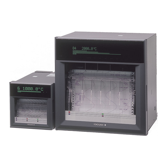
Names of Parts and Basic Key Operations Display and Keys You use the panel keys and the display to configure the communication functions. For a description of other parts of the recorder, see section 3.1 in the Recorder User’s Manual . (The figure below is of the µR10000 Recorder.) Front Rear Panel... - Page 7 Names of Parts and Basic Key Operations Basic Key Operations This section describes basic operations on the front panel keys to change various settings. • Execution Modes The recorder has the following execution modes. • Operation mode: A mode used to perform recording and monitoring. •...
- Page 8 Names of Parts and Basic Key Operations • Entering Values Use the key or SHIFT + key to move the cursor. Use the key or SHIFT key to change a digit value. You repeat these steps to enter the value. SHIFT key + A=000.000.000.000 Target digit...
- Page 9 Names of Parts and Basic Key Operations Deleting an Entire Character String Press the CHARACTER key or SHIFT + CHARACTER key to show Clear DISP and then press the key. The entire character string is deleted. Copying & Pasting a Character String Show the copy source character string.
-
Page 10: Table Of Contents
Contents Foreword ............................i Functional Enhancement of the Recorder ..................ii How to Use This Manual ........................ iii Names of Parts and Basic Key Operations ..................v Chapter 1 Overview of the Communication Functions Communication Functions Using the Ethernet Interface (/C7 Option) ......1-1 Functional Construction .................... - Page 11 Contents Chapter 4 Commands Command Syntax ......................4-1 Response ......................... 4-2 A List of Commands ......................4-3 Execution Modes and User Levels .................. 4-3 Setting Commands ......................4-3 Basic Setting Commands ....................4-4 Control Commands ......................4-5 Output Commands ......................4-5 RS-422A/485 Dedicated Commands ................
- Page 12 Contents Appendix Appendix 1 ASCII Character Codes ..................App-1 Appendix 2 Output Flow of FIFO Data ..................App-2 Appendix 3 Login Procedure ....................App-4 Appendix 4 A List of Error Messages ..................App-6 Index Index IM 04P01B01-17E...
-
Page 13: Chapter 1 Overview Of The Communication Functions
Chapter 1 Overview of the Communication Functions Communication Functions Using the Ethernet Interface (/C7 Option) The recorder can be equipped with an optional Ethernet interface. For details on how to use the Ethernet interface, see chapter 2. Functional Construction The following figure shows the relationship between the communication function of the recorder and the Ethernet interface. -
Page 14: Maintenance/Test Server
1.1 Communication Functions Using the Ethernet Interface (/C7 Option) Maintenance/Test Server • Outputs Ethernet communication information such as connection information and network statistics from the recorder. • The commands that can be used Maintenance/Test commands. <Related Topics> • Ethernet interface settings: Section 2.3 •... -
Page 15: Other Functions
1.1 Communication Functions Using the Ethernet Interface (/C7 Option) Other Functions • Login Function Only users that are registered in advance can access the Setting/Measurement and Maintenance/Test servers. • Users are identified by their user name and password. • You can register one administrator and six users. Administrator privileges The administrator can use all the functions on the Setting/Measurement and Maintenance/Test servers... -
Page 16: Communication Functions Using The Rs-422A/485 Communication
Communication Functions Using the RS-422A/ 485 Communication Interface (/C3 Option) The recorder can be equipped with an optional RS-422A/485 communication interface. For details on how to use the RS-422A/485 communication interface, see chapter 3. Functional Construction The following figure shows the relationship between the communication function of the recorder and the RS-422A/485 communication interface. -
Page 17: Chapter 2 Using The Ethernet Interface (/C7 Option)
Chapter 2 Using the Ethernet Interface (/C7 Option) Ethernet Interface Specifications Basic Specifications Item Specifications Electrical and mechanical specifications Conforms to IEEE 802.3 (Ethernet frames are of DIX specification) Transmission medium type 10BASE-T Protocol TCP, IP, UDP, ICMP, and ARP The Maximum Number of Simultaneous Connections and the Number of Simultaneous The following table shows the maximum number of simultaneous connections, the number of simultaneous users, and the port numbers of the recorder. -
Page 18: Connecting The Ethernet Interface
Connecting the Ethernet Interface When Connecting Only the Recorder and a PC Connect the recorder and the PC via a HUB as in the following figure. µR10000/µR20000 Recorder 10BASE-T straight cable µR10000/µR20000 Recorder 10BASE-T straight cable When Connecting to a Preexisting Network The following figure illustrates an example in which a recorder and a PC are connected to the network. -
Page 19: Configuring The Ethernet Interface
Configuring the Ethernet Interface Set the host name and IP address of the recorder. You do not have to set the DNS (domain name system). Setup Items Ethernet Host Host Domain Host name Domain name Local IP IP address Subnet mask Default gateway DNS On/Off Server... - Page 20 2.3 Configuring the Ethernet Interface IP Address, Subnet Mask, and Default Gateway Press the key to select Ethernet and then press the key. Basic=Ethernet Press the key to select Local IP and then press the key. Ethernet=Local IP Set the IP address of the recorder and then press the key.
- Page 21 2.3 Configuring the Ethernet Interface Set the primary domain suffix and then press the key. Key operations • Use the key to select the digit for entering a character. • Use the CHARACTER key to select the character type. • Use the key to select the character you wish to enter.
- Page 22 2.3 Configuring the Ethernet Interface • G (Default Gateway) • Set the IP address of the gateway (router, etc.) used to communicate with other networks. The default value is 0.0.0.0. • Set this value according to the system or the network to which the recorder belongs.
-
Page 23: Checking The Connection Status
Checking the Connection Status The connection status of the Ethernet interface can be confirmed with the indicator that is located to the left of the Ethernet port on the recorder. Indicator Connection Status of the Ethernet Interface ON (Green) The Ethernet interface is electrically connected. Blinking (Green) Transmitting data. -
Page 24: Registering Users
Registering Users Users that can access the recorder via the Ethernet network must be registered. This function is called login function. Setup Items Ethernet Login Login Use/Not LoginSet Level Register User Admin/User On/Off User name Password Procedure For a description of the basic operations, see “Basic Key Operations” on page vi. Entering Basic Setting Mode Hold down the key for 3 seconds to display the Setting mode screen. - Page 25 2.5 Registering Users Set the user name and then press the key. Key operations • Use the key to select the digit for entering a character. • Use the CHARACTER key to select the character type. • Use the key to select the character you wish to enter. User= Set the password and then press the key in the same fashion as in step 8.
- Page 26 2.5 Registering Users Note • The relationship between the login function and the user name that is used when accessing the recorder is as follows: • When the login function is set to “Use” • The registered user name and password can be used to login to the recorder. •...
-
Page 27: Setting The Communication Timeout And Keepalive
Setting the Communication Timeout and Keepalive The communication timeout function and the keepalive function can be configured. Setup Items Ethernet Timeout Timeout Duration On/Off Timeout time K.Alive Keep alive On/Off Procedure For a description of the basic operations, see “Basic Key Operations” on page vi. Entering Basic Setting Mode Hold down the key for 3 seconds to display the Setting mode screen. - Page 28 2.6 Setting the Communication Timeout and Keepalive Keepalive Press the key to select Ethernet and then press the key. Basic=Ethernet Press the key to select K.Alive and then press the key. Ethernet=K. Alive Press the key to select On and then press the key.
-
Page 29: Chapter 3 Using The Rs-422A/485 Communication Interface (/C3 Option)
Chapter 3 Using the RS-422A/485 Communication Interface (/C3 Option) RS-422A/485 Communication Interface Specifications This section describes the RS-422A/485 communication interface specifications. Item Specifications Terminal block type Number of terminals: 6, terminal attachment screws: ISO M4/nominal length of 6 mm Electrical and mechanical Complies with the EIA-422A(RS-422A) and specifications EIA-485(RS-485) standards... -
Page 30: Terminal Arrangement And Signal Names
Terminal Arrangement and Signal Names and the Connection Procedure of the RS-422A/485 Communication Interface Terminal Arrangement and Signal Names Rear panel ALARM CHART SDA SDB SG RS-422A REMOTE SD SD SG RS-422A SD SD SG RD RD FG RD RD FG RDA RDB FG Terminal Name Description... -
Page 31: Connection Example With A Host Computer
3.2 Terminal Arrangement and Signal Names and the Connection Procedure of the RS-422A/485 Communication Interface WARNING To prevent the possibility of electric shock, connect the cables with the power turned OFF. Note • Connect the RD pin to the SD (TD) pin on the PC (converter) end and the SD pin to the RD pin on the PC end. - Page 32 3.2 Terminal Arrangement and Signal Names and the Connection Procedure of the RS-422A/485 Communication Interface (The following figure illustrates the case when the host computer’s interface is RS-232.) Host computer Terminator (external) Terminator (external) 120 Ω 1/2W or greater RS-422A/485 RS-232 terminal on the recorder...
- Page 33 MODEL RC-57 by RA SYSTEMS CORP. CAUTION Some converters not recommended by Yokogawa have FG and SG pins that are not isolated. In this case, do not connect anything to the converter’s FG and SG pins (unlike the figure on the previous page). Especially in the case of long distance communications, the potential difference that appears may damage the recorder or cause communication errors.
- Page 34 When the instrument that support only the RS-422A interface exist in the system The maximum number of connection is 16. Some of YOKOGAWA’s conventional recorder only support the RS-422A driver. In this case, only up to 16 units can be connected.
-
Page 35: The Bit Structure Of One Character And The Operation Of The Receive Buffer
The Bit Structure of One Character and the Operation of the Receive Buffer The Bit Structure of One Character The serial interface on the recorder communicates using start-stop synchronization. In start-stop synchronization, a start bit is added every time a character is transmitted. The start bit is followed by the data bits, parity bit, and stop bit. -
Page 36: Modbus Slave Protocol Specifications
Modbus Slave Protocol Specifications The Modbus slave protocol specifications of the recorder are as follows: Serial Interface Item Specifications Transmission medium RS-422A/485 Flow control None only Baud rate Select from 1200, 2400, 4800, 9600, 19200, or 38400 [bps] Start bit Fixed to 1 bit Stop bit Fixed to 1 bit... -
Page 37: Registers
3.4 Modbus Slave Specifications Registers The registers for using the Modbus slave protocol are listed below. Binary values are stored to the register in order from the highest byte. Input Register Data 30001 Measured data of CH01 30002 Measured data of CH02 30003 Measured data of CH03 30004... - Page 38 3.4 Modbus Slave Protocol Specifications Input Register Data 32001 Computed data of CH0A (lower word) 32002 Computed data of CH0A (upper word) 32003 Computed data of CH0B (lower word) 32004 Computed data of CH0B (upper word) 32005 Computed data of CH0C (lower word) 32006 Computed data of CH0C (upper word) 32007...
- Page 39 3.4 Modbus Slave Specifications Input Register Data 33001 Alarm status of the computed data of CH0A 33002 Alarm status of the computed data of CH0B 33003 Alarm status of the computed data of CH0C 33004 Alarm status of the computed data of CH0D 33005 Alarm status of the computed data of CH0E 33006...
- Page 40 3.4 Modbus Slave Protocol Specifications Hold register Data 40001 Communication input data of C01 40002 Communication input data of C02 40003 Communication input data of C03 40004 Communication input data of C04 40005 Communication input data of C05 40006 Communication input data of C06 40007 Communication input data of C07 40008...
-
Page 41: Modbus Error Response
3.4 Modbus Slave Specifications (From previous page) Hold register Data 40325 Communication input data of C13 (lower word) 40326 Communication input data of C13 (upper word) 40327 Communication input data of C14 (lower word) 40328 Communication input data of C14 (upper word) 40329 Communication input data of C15 (lower word) 40330... -
Page 42: Setting The Serial Interface
Setting the Serial Interface The serial interface must be configured. Setup Items RS422/485 Address Baud rate Data length Parity Protocol Procedure For a description of the basic operations, see “Basic Key Operations” on page vi. Entering Basic Setting Mode Hold down the key for 3 seconds to display the Setting mode screen. - Page 43 3.5 Setting the Serial Interface Explanation • Address Select the address from the following range. 01 to 32 • Baud rate Select the baud rate from the following: 1200, 2400, 4800, 9600, 19200, or 38400 • Data length Select the data length from below. To output data in BINARY format, be sure to set the data length to 8 bits.
-
Page 44: Chapter 4 Commands
Chapter 4 Commands Command Syntax The syntax of the setting/basic setting/output commands (see sections 4.4 to 4.7) of the instrument is given below. ASCII codes (see appendix 1) are used for the character codes. For the Maintenance/Test command syntax, see section 4.9. For the Instrument Information server command syntax, see section 4.10. -
Page 45: Response
4.1 Command Syntax • Query • A question mark is used to specify a query. • By placing a query after a command or parameter, the setting information of the corresponding command can be queried. Some commands cannot execute queries. For the query syntax of each command, see sections 4.4 to 4.7. Example 1 SR[ p1]? SR? or SR p1? can be executed. -
Page 46: A List Of Commands
A List of Commands Execution Modes and User Levels Execution Modes The recorder has two execution modes. Each command is specified to be used in a particular execution mode. If you attempt to execute a command in a mode that is different from the specification, a syntax error occurs. -
Page 47: Basic Setting Commands
4.2 A List of Commands Basic Setting Commands Note • The settings that are returned in response to a query in the basic setting mode will contain the new settings even if they are not saved. • In order to activate the settings that are changed using the basic setting commands, the settings must be saved using the YE or XE command. -
Page 48: Control Commands
4.2 A List of Commands Control Commands Command Function Execution Mode Administrator User Page Name Switches the execution mode. All modes 4-28 Starts/Stops recording. Run mode 4-28 DISP Switches the screen/switches the channel. Run mode 4-28 FUNC AK Executes alarm acknowledge (AlarmACK) Run mode 4-28 FUNC TL... -
Page 49: Maintenance/Test Commands
4.2 A List of Commands Maintenance/Test Commands These commands can be used only when using Ethernet communications. Command Name Function Execution Mode Administrator User Page close Disconnects the connection between other instruments. All modes 4-32 Outputs connection information. All modes 4-32 Output Ethernets statistical information. -
Page 50: Parameter Values
Parameter Values This section explains frequently used parameters. Input Range The following tables show the input types (VOLT, TC, RTD, DI, and 1-5V), range types, and the ranges for the leftmost and rightmost values of the span. • DC Voltage (VOLT), Square Root (SQRT), Difference between Channels (DELTA) Range Type Parameter for Range of Leftmost and... - Page 51 4.3 Parameter Values • Resistance Temperature Detector (RTD) Range Type Parameter for Range of Leftmost and Rightmost Values of Span the SR Command SR Command SR Command °C °F Pt100 –200.0 to 600.0°C –2000 to 6000 –328.0 to 1112.0°F –3280 to 11120 JPt100 –200.0 to 550.0°C –2000 to 5500...
-
Page 52: Miscellaneous
4.3 Parameter Values Miscellaneous Channel Number • Pen model Measurement channel: 01 to 04 Computation channel: 0A, 0B, 0C, 0D, 0E, 0F, 0G, 0J • Dot model Measurement channel: µR10000: 01 to 06 µR20000: 01 to 24 Computation channel: µR10000: 0A, 0B, 0C, 0D, 0E, 0F, 0G, 0J, 0K, 0M, 0N, 0P µR20000: 0A, 0B, 0C, 0D, 0E, 0F, 0G, 0J, 0K, 0M, 0N, 0P, 1A, 1B, 1C, 1D, 1E, 1F, 1G, 1J, 1K, 1M, 1N, 1P Relay Number (/A1, /A2, /A3, /A4, and /A5 Options) -
Page 53: Setting Commands
4.4 Setting Commands Setting Commands Description • This command cannot be specified while computation is in progress. • For p3 and p4, enter an integer value of 5 Sets the input range. digits or less according to the table in section When setting channels to skip 4.3. - Page 54 4.4 Setting Commands Description • This command cannot be specified while Description • Set p3 in the range of ±10% of the span of the computation is in progress. measurable range at the range type or ±10% • Set p4 according to the table in section 4.3. of the scaling span.
- Page 55 4.4 Setting Commands p3 Alarm ON/OFF state (ON) • For scaling (1-5V, scaling, and square p4 Alarm type root): −5 to 105% of the scale span (except H High limit alarm within −20000 to 30000). L Low limit alarm • Parameter p5 for the difference high limit h Difference high limit alarm alarm/difference low limit alarm: Values in the l Difference low limit alarm...
- Page 56 4.4 Setting Commands Sets the chart speed. Sets zone recording. Syntax SC p1<terminator> Syntax SZ p1,p2,p3<terminator> p1 Chart speed p1 Channel number Query p2 Leftmost position of the zone (µR10000: 0 Example Set the chart speed to 25 mm/h. to 95, µR20000: 0 to 175) [mm] p3 Rightmost position of the zone (µR10000: 5 SC 25 Description Select the chart speed from the list of choices...
- Page 57 4.4 Setting Commands Turns ON/OFF the recording on Query each channel. Example Set the chart speed to 50 mm/h. SE 50 Dot model Description Select the chart speed from the list of choices Syntax VR p1,p2,p3<terminator> below. p1 Channel number Pen model p2 Trend recording ON/OFF (ON, OFF) 5 to 12000 mm/h (82 levels, see section 4.3)
- Page 58 4.4 Setting Commands Sets the computing equation Example Set the display (VFD) brightness to 2 and the (/M1 option). internal illumination to 1. VF 2,1 Syntax SO p1,p2,p3,p4,p5,p6<terminator> Description The brightness increases as the value increases. p1 Computation channel number p2 Turn ON/OFF the computing equation (ON, Sets the DST.
- Page 59 4.4 Setting Commands On screens with the displayed channel switching Query SJ[ p1]? interval Example Enable timer 1 on computation channel 0B. No sum scale designation. Syntax VD p1,p2,p3<terminator> SJ 0B,1,OFF p1 Screen number (01 to 15) Description • This command cannot be specified while p2 Display type computation is in progress.
- Page 60 4.4 Setting Commands Example Assign the 2-channel digital display to screen 04 TIME/Chart speed and automatically switch the displayed channels Date/Time/Chart speed (µR20000) every 5 seconds. Channel alarm status Channel alarm status display VD 04,2CH digital,AUTO5S STATUS For flag display Status display Syntax VD p1,p2,p3<terminator>...
- Page 61 4.4 Setting Commands Query Example Set character string Product as a batch number. VD[ p1]? Example Assign the display in which different screens can VH BATCH,Product be assigned to the top and bottom sections to Description Valid with the header printout (/BT1 option) when screen 09.
- Page 62 4.4 Setting Commands Turns Start printout/End printout Example Set feed amount after End printout to 10 mm. ON/OFF (/BT1 option). VA END,10 Description • Valid with the header printout (/BT1 option) Syntax VP p1,p2,p3,p4<terminator> when set to use Start printout/End printout p1 Mode selection (see the UE command).
-
Page 63: Basic Setting Commands
4.4 Setting Commands/4.5 Basic Setting Commands Basic Setting Commands Measured value of CH01 (7 characters) Measured value of CH02 • In order to activate the settings that are (7 characters) changed using the basic setting commands, the settings must be saved using the YE or Measured value of CH24 XE command. - Page 64 4.5 Basic Setting Commands p5 Hold/Not hold the relay • If Auto is specified when using the 24-VDC HOLD Hold the relay output until an power supply on a recorder with the 24-VDC/ alarm acknowledge operation AC power supply (/P1 option), the integration is executed time is fixed to 20 ms (50 Hz).
- Page 65 4.5 Basic Setting Commands Example Set the dot color of channel 06 to purple. p2 Reference time (00 to 23 [hour]) UC 06,PURPLE p3 Interval (10min, 12min, 15min, 20min, Description On models with the computation function (/M1 30min, 1h, 2h, 3h, 4h, 6h, 8h, 12h, 24h) option), the dot color of computation channels (when p1 is Manual) can be changed.
- Page 66 4.5 Basic Setting Commands Selects the date format. • On models with the computation function (/M1 option), computation channels can be Syntax XN p1<terminator> specified. p1 Date format for displaying and printing Y/M/D: (example) 2005/08/31 Sets the display mode of the bar M/D/Y: (example) 08/31/2005 graph.
- Page 67 4.5 Basic Setting Commands • Parameter p5 can be specified on models with Priority R_RCD the calibration correction (/CC1 option). Use Priority to remote the UQ and VL commands to set the recording correction values. BatchCMT switch Batch comment Selects the time printout format. switching Syntax UT p1,p2,p3,p4<terminator>...
- Page 68 4.5 Basic Setting Commands p6 Printout ON/OFF (ON, OFF) Example When the computed result is in error, handle the Query XQ[ p1]? error data as +OVER. Use the limit value given Example Set an absolute timer to timer number 1. Set the by the recorder for computation instead of the interval to 30 minutes, the reference time to hour “input over”...
- Page 69 4.5 Basic Setting Commands p3 Number of calibration set points (2 to 16) Description The settings specified by this command and Query UQ[ p1]? saved using the XE command take effect after Example Set the setting mode to Abs.Value and the the recorder is power cycled.
- Page 70 4.5 Basic Setting Commands When p1 = FULL Example Display all menus. µR10000: An integer between –30 to 30 UH ON,ON,ON,ON,ON (reference value: 1000) Selects enable/disable for Start µR20000: An integer between –50 to 50 printout/End printout and (reference value: 1800) message format (/BT1 option).
-
Page 71: Control Commands
4.6 Control Commands Starts/stops/resets computation Control Commands (/M1 option). Syntax TL p1<terminator> Switches the execution mode. p1 Operation type Syntax DS p1<terminator> 0 Computation start p1 Mode 1 Computation stop 0 Run mode 2 Computation reset 1 Basic Setting mode Example Start the computation. -
Page 72: Output Commands
4.6 Control Commands/4.7 Output Commands Clears the message printout Output Commands buffer. Syntax MC p1<terminator> Sets the byte output order. p1 Clear the message printout buffer (0) Syntax BO p1<terminator> Example Clear the message printout buffer. p1 Byte order MC 0 0 Outputs the data MSB first. - Page 73 4.7 Output Commands Disconnects an Ethernet Report Output the statistical calculation connection (/C7 option). data of periodic printout (report data) Syntax CC p1<terminator> Tlog1 Output the data at the most p1 Disconnect the connection (0) recent timeout of TLOG timer 1 Example Disconnect the connection.
-
Page 74: Rs-422A/485 Dedicated Commands
4.7 Output Commands/4.8 RS-422A/485 Dedicated Commands RS-422A/485 Dedicated Newest value output (GETNEW) Output the specified number of blocks (p4) of Commands FIFO data back starting from the recent acquire position (block). • Parameters p2, p3, and p4 are valid when p1 ESC O Opens the instrument. -
Page 75: Maintenance/Test Commands
4.9 Maintenance/Test Commands Outputs Ethernet statistical Maintenance/Test information. Commands (Available when Syntax eth<terminator> using the maintenance/test Example server function via Ethernet communications) 04/10/01 12:34:56 Ethernet Statistics close Disconnects the connection between other instruments. Name In Pkt In Err Out Pkt Out Err 16 Coll Syntax close,p1,p2:p3<terminator>... -
Page 76: Server Function Via Ethernet Communications)
4.9 Maintenance/Test Commands/4.10 Instrument Information Output Commands 4.10 Instrument Information TCP: keepalive Keepalive check cycle. Output Commands TCP: connects (Available when using the Total number of connections established. TCP: closed instrument information Total number of dropped connections. server function via TCP: timeoutdrop Total number of dropped connections due to Ethernet communications) -
Page 77: Chapter 5 Responses
Chapter 5 Responses Response Syntax The following table shows the types of responses for various commands described in the previous chapter. The recorder returns a response (affirmative/negative response) to a command that is separated by a single terminator. The controller should follow the one command to one response format. -
Page 78: Ascii Output
5.1 Response Syntax • Example E2 02:001 ASCII Output The following types of ASCII data are available. For the data formats, see section 5.2. Setting data, basic setting data, decimal position/unit information, measured/ computed data, report data generated by the periodic printout, status information, and user information •... - Page 79 5.1 Response Syntax • Flag Name (Abbreviation) Flag Flag Meaning of the Flag Output byte order Existence of a checksum – – – – – – – – – – – – – – – Reserved – – Fixed to 1. •...
- Page 80 5.1 Response Syntax If the data length of the buffer is odd, a “0” is padded so that it is even. (1) through (6) are summed as unsigned two-byte integers (unsigned short). If the digit overflows a “1” is added. Finally, the result is bit-wise inverted. Sample Program The sum value is determined using the following sample program, and the calculated result is returned.
-
Page 81: Rs-422A/485 Dedicated Commands And Responses
5.1 Response Syntax RS-422A/485 Dedicated Commands and Responses The following table shows dedicated commands for the RS-422A/485 interface and their responses. Command Syntax Meaning Response ESC O_xx CRLF Open the instrument. • Response from the instrument with the specified address ESC O xx CRLF (_ space) •... -
Page 82: Output Format Of Ascii Data
Output Format of ASCII Data The following types of ASCII data are available. • Setting data/Basic Setting data • Decimal point position/unit information • Measured/computed data • Report data generated by the periodic printout • Status information • User information Note The “CRLF”... -
Page 83: Decimal Point Position/Unit Information
5.2 Output Format of ASCII Data Decimal Point Position/Unit Information • The FE command (FE1) is used to output the data. • Syntax The data is output for each channel in the following syntax. EACRLF s_kccuuuuuu,ppCRLF •••••••••••••••••• ENCRLF Data status (N, D, S) N: Normal D: Differential input S: Skip (When the input range is set to SKIP for a measurement... -
Page 84: Measured/Computed Data
5.2 Output Format of ASCII Data Measured/computed Data • The FD (FD0) or FY (FYInst, FYTlog1, or FYTlog2) command is used to output the data. • Syntax The measured/computed data are output in the following syntax along with the date and time information for each channel EACRLF DATE_yy/mo/ddCRLF... - Page 85 5.2 Output Format of ASCII Data Each status is set to H, L, h, l, R, r, T, t, or space. H: high limit alarm, L: low limit alarm, h: difference high-limit alarm, l: difference low-limit alarm, R: high limit on rate-of- change alarm, r: low limit on rate-of-change alarm, T: delay high limit alarm, t: delay low limit alarm, space: no alarm uuuuuu...
-
Page 86: Report Data Generated By The Periodic Printout
5.2 Output Format of ASCII Data Report Data Generated by the Periodic Printout • The FY command (FYREPORT) is used to output the data. • Report data generated by the periodic printout is output. Syntax EACRLF YY/MO/DD_HH:MI:SS.MMMTCRLF yy/mo/dd_hh:mi:ss.mmmt_S CRLF kccuuuuuuf dddddEf pp_f dddddEf... - Page 87 5.2 Output Format of ASCII Data dddddEf pp_f dddddEf pp_f dddddEf pp_f dddddEf pp_f dddddddd The data is output in the following order: most recent value, minimum value, maximum value, average value, and sum value. dddddEf pp Most recent value, minimum value, maximum value, and average value of the measurement channel ddddddddEf Sum value of the measurement channel or the most recent...
-
Page 88: Status Information
5.2 Output Format of ASCII Data Status Information • The IS command is used to output the data. • The operation status of the recorder is output • For details on the status information, see section 6.2, “The Bit Structure of the Status Information.”... -
Page 89: Output Format Of Binary Data
Output Format of BINARY Data This section describes the output format of the BINARY data that is disclosed. For the BINARY output format, see “BINARY Output” on page 5-2. For other BINARY data types, see “Identifier” on page 5-3. The measured data is output using signed 16-bit integer; the computed data is output using signed 32-bit integer. - Page 90 5.3 Output Format of BINARY Data • Flag The meanings of the flags are given on the table below. The flags are valid during FIFO data output. The flags are undefined for other cases. Flag Flag Meaning of the Flag –...
-
Page 91: Chapter 6 Status Information
Chapter 6 Status Information Status Information and Filter The following figure illustrates the status information and filter on the recorder. 4 bytes Status information Filter Condition register • When a status indicated on the following page is entered, the corresponding bit in the condition register is set to “1.”... -
Page 92: The Bit Structure Of The Status Information
The Bit Structure of the Status Information The following four groups of status information are output in response to a status information output request using the IS command. For the output format, see “Status Information” in section 5.2, “Output Format of ASCII Data.” Status Information 1 Name Description... - Page 93 Appendix Appendix 1 ASCII Character Codes The table below shows characters each command can use. Command Used for Characters Unit Alphanumeric characters, signs, and space Alphanumeric characters, signs, and space Message Alphanumeric characters, signs, and space Host/Domain name Alphanumeric characters and signs Domain suffix Alphanumeric characters and signs Computing equation...
-
Page 94: Appendix
Appendix 2 Output Flow of FIFO Data The recorder has a dedicated internal memory for outputting measured/computed data. This memory is structured as a FIFO (First-In-First-Out). Measured/computed data are constantly acquired to the internal memory at the specified acquiring interval (FIFO acquiring interval, set with the FR command). - Page 95 Appendix 2 Output Flow of FIFO Data Example in which the FIFO acquiring interval on the recorder is set to 1 s and the measured data from channel 01 to 06 are continuously output (logging function) Command to send START Command description Received response data Send command...
- Page 96 Appendix 3 Login Procedure When using the Setting/Measurement server or the Maintenance/Test server via the Ethernet interface (/C7 option), you must log into the recorder from the PC. If you complete the procedure successfully up to login complete in the following figure, the commands in chapter 4 become functional.
-
Page 97: Appendix 3 Login Procedure
Appendix 3 Login Procedure When not using the login function Login as “admin” or “user.” • The user name “admin” can be used to login to the recorder as an administrator. • The user name “user” can be used to access the recorder as a user. Connect Within the number of E1 421... -
Page 98: Appendix 4 A List Of Error Messages
The error messages and their description are listed below. Setting Errors Code Message Explanation/Countermeasures System error. Contact your nearest YOKOGAWA dealer. Incorrect date or time setting. Check the setting. A disabled channel is selected. The channel does not exist. Incorrect function parameter. - Page 99 Appendix 4 A List of Error Messages Code Message Explanation/Countermeasures All items in DISP menu parameters are set to SKIP. – Start = Finish. The DST start time and end time cannot be set to the same time. Invalid or missing DST time settings. Since the time gains one hour when the DST starts, the set-up time does not exist.
- Page 100 Settings and measured data have been initialized. System Errors Code Message Explanation/Countermeasures RAM failure. Contact your nearest YOKOGAWA dealer. A/D error. Contact your nearest YOKOGAWA dealer. A/D calibration value error. Contact your nearest YOKOGAWA dealer. A/D calibration is in the wrong order.
-
Page 101: Index
Index FF ................4-30 Symbols FR ................4-18 FU ................4-31 1-5V input low-cut ............. 4-23 FY ................4-30 help ................4-32 host ................4-33 IF ................4-29 A/D integral time ............... 4-21 ip ................. 4-33 address ................3-15 IS ................4-31 administrator ............... - Page 102 Index VL ................4-11 entering values ..............vii VM ................4-19 error messages .............. App-6 VP ................4-19 ESC key ................vi VR ................4-14 Ethernet interface ..............2-1 VT ................4-13 Ethernet statistical information .......... 4-32 XA ................4-20 execution mode ..............
- Page 103 Index measured/computed data ..........4-30 setup data ................. 4-30 measured/computed data output ........5-8 setup list (basic setting information) printout ..... 4-28 menu selection ..............4-27 simultaneous users ............. 2-1 message ..............4-14, 4-28 special data value ............. 5-14 message format ............4-19, 4-27 square root low-cut ............
Need help?
Do you have a question about the Vigilantplant mR10000 and is the answer not in the manual?
Questions and answers