Siemens SIPART PS2 Operating Instructions Manual
Electropneumatic positioners with profibus pa
Hide thumbs
Also See for SIPART PS2:
- Diagnostic manual (592 pages) ,
- Operating instructions manual (372 pages) ,
- Compact operating instructions (294 pages)

Related Manuals for Siemens SIPART PS2


Summary of Contents for Siemens SIPART PS2
- Page 1 SIPART Electropneumatic positioners SIPART PS2 with PROFIBUS PA (6DR55..) Operating Instructions 02/2016 Edition Answers for industry.
- Page 3 Introduction Safety information Description SIPART Installing/mounting Electropneumatic positioner SIPART PS2 with PROFIBUS PA Connect Operation Operating Instructions Commissioning Functional safety Parameter assignment Functions/operations using PROFIBUS PA Alarm, fault and system messages Service and maintenance Technical data Dimension drawings 6DR55.. Spare parts / accessories /...
- Page 4 Note the following: WARNING Siemens products may only be used for the applications described in the catalog and in the relevant technical documentation. If products and components from other manufacturers are used, these must be recommended or approved by Siemens. Proper transport, storage, installation, assembly, commissioning, operation and maintenance are required to ensure that the products operate safely and without any problems.
-
Page 5: Table Of Contents
Overview of device components (Ex)..................27 3.3.3 Basic electronics........................28 Functional principle........................28 3.4.1 PROFIBUS system configuration...................30 3.4.2 SIMATIC PDM........................31 PROFIBUS PA........................31 3.5.1 Overview..........................31 3.5.2 Transmission technology.......................31 3.5.3 Bus topology..........................32 3.5.4 Properties..........................33 3.5.5 Profile.............................33 3.5.6 Connection..........................33 SIPART PS2 with PROFIBUS PA Operating Instructions, 02/2016, A5E00127926-AB... - Page 6 M12 connector for connecting the outputs of the position feedback module 6DR4004-6J / 8J (-Z D53)..........................95 5.2.6.4 M12 connector for connecting the external position detection system (-Z D54)....95 5.2.6.5 M12 connector for connecting the outputs of the SIA module 6DR4004-6G /-8G (-Z D56)..95 SIPART PS2 with PROFIBUS PA Operating Instructions, 02/2016, A5E00127926-AB...
- Page 7 Manual initialization of part-turn actuators................133 Device replacement......................136 Functional safety............................139 Range of applications for functional safety................139 Safety function........................139 Safety Integrity Level (SIL)....................140 Settings..........................142 Safety characteristics......................143 Maintenance/check......................143 Parameter assignment..........................145 Introduction to parameter assignment section..............145 SIPART PS2 with PROFIBUS PA Operating Instructions, 02/2016, A5E00127926-AB...
- Page 8 9.3.3.9 Monitoring the high limit temperature 'J.\\TMAX'..............190 9.3.3.10 Monitoring the number of total strokes 'L.\\STRK'..............192 9.3.3.11 Monitoring the number of changes in direction 'O.\\DCHG'..........193 9.3.3.12 Monitoring the position average value 'P.\\PAVG'..............195 SIPART PS2 with PROFIBUS PA Operating Instructions, 02/2016, A5E00127926-AB...
- Page 9 10.3.3.3 Definition of the status......................236 10.3.3.4 Sub-status for deactivated condensed status..............236 10.3.3.5 Sub-status for activated condensed status................237 10.3.3.6 List of diagnostics events with status and diagnostics message for deactivated condensed status.........................237 SIPART PS2 with PROFIBUS PA Operating Instructions, 02/2016, A5E00127926-AB...
- Page 10 Diagnostic value '47.PRUP - Prediction UP' / '48.PRDN - Prediction DOWN'.....266 11.2.4.31 Diagnostic value '49.WT00' ... '56.WT95' - Number of operating hours in the travel range WT00 to WT95........................266 11.3 Online diagnostics........................267 11.3.1 Overview of online diagnostics.....................267 SIPART PS2 with PROFIBUS PA Operating Instructions, 02/2016, A5E00127926-AB...
- Page 11 12.6 Disposal..........................281 Technical data............................283 13.1 Rated conditions........................283 13.2 Pneumatic data........................284 13.3 Construction.........................284 13.4 Controller..........................286 13.5 Certificates, approvals, explosion protection................287 13.6 Electrical specifications......................288 13.7 Technical data for natural gas as actuator medium.............290 SIPART PS2 with PROFIBUS PA Operating Instructions, 02/2016, A5E00127926-AB...
- Page 12 Scope of delivery of mechanical limit switch module............308 15.6 Scope of delivery EMC filter module ...................308 15.7 Accessories..........................309 Appendix..............................311 Operation with boosters.......................311 Certificates...........................312 Technical support.........................312 Abbreviations............................313 Abbreviations for positioners....................313 Abbreviations for functional safety..................314 Glossary..............................317 Index.................................325 SIPART PS2 with PROFIBUS PA Operating Instructions, 02/2016, A5E00127926-AB...
-
Page 13: Introduction
7.HOURR > Resettable operating hours counter added. – 11.LEAK > Offline leakage test added. – 21.P0 and 22.P100 > Modification of upper and lower endstops now possible without initialization. – 25.PAUTP > Adjustable pulse pause added. SIPART PS2 with PROFIBUS PA Operating Instructions, 02/2016, A5E00127926-AB... -
Page 14: Purpose
4. Check the scope of delivery by comparing your order to the shipping documents for correctness and completeness. WARNING Using a damaged or incomplete device Danger of explosion in hazardous areas. ● Do not use damaged or incomplete devices. SIPART PS2 with PROFIBUS PA Operating Instructions, 02/2016, A5E00127926-AB... -
Page 15: Transportation And Storage
The content reflects the technical status at the time of publishing. Siemens reserves the right to make technical changes in the course of further development. - Page 16 Introduction 1.7 Notes on warranty SIPART PS2 with PROFIBUS PA Operating Instructions, 02/2016, A5E00127926-AB...
-
Page 17: Safety Information
Further provisions for hazardous area applications are for example: ● IEC 60079-14 (international) ● EN 60079-14 (EC) Conformity with European directives The CE marking on the device shows conformity with the regulations of the following European guidelines: SIPART PS2 with PROFIBUS PA Operating Instructions, 02/2016, A5E00127926-AB... -
Page 18: Improper Device Modifications
If you need additional information not covered by these instructions, contact your local Siemens office or company representative. Note Operation under special ambient conditions... -
Page 19: Use In Hazardous Areas
● Connect the device with type of protection "Intrinsic safety" solely to an intrinsically safe circuit. ● Observe the specifications for the electrical data on the certificate and/or in Chapter "Technical data". SIPART PS2 with PROFIBUS PA Operating Instructions, 02/2016, A5E00127926-AB... - Page 20 Safety information 2.7 Use in hazardous areas SIPART PS2 with PROFIBUS PA Operating Instructions, 02/2016, A5E00127926-AB...
-
Page 21: Description
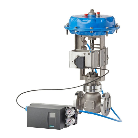
It functions as a slave and communicates with the master through the PROFIBUS PA fieldbus. Apart from communication, the fieldbus also supplies electrical auxiliary power to the positioner. SIPART PS2 with PROFIBUS PA Operating Instructions, 02/2016, A5E00127926-AB... - Page 22 ● Integrated addition to SAMSON in non-flameproof aluminum enclosure ① Pressure gauge block, single-acting ② Valve ③ Yoke / actuator yoke ④ Single-acting positioner in non-flameproof aluminum enclosure ⑤ Actuator Figure 3-1 Positioner attached to a single-acting linear actuator SIPART PS2 with PROFIBUS PA Operating Instructions, 02/2016, A5E00127926-AB...
- Page 23 Positioner attached to double-acting part-turn actuator ① Single-acting positioner in flameproof aluminum enclosure ② Pressure gauge block, single-acting ③ Yoke / actuator yoke ④ Actuator Figure 3-3 Positioner in flameproof aluminum enclosure attached to linear actuator SIPART PS2 with PROFIBUS PA Operating Instructions, 02/2016, A5E00127926-AB...
-
Page 24: Nameplate Layout
Ordering supplement (Order code) ⑥ ⑬ QR code to the mobile website with device-spe‐ Article number cific information on the product ⑦ ⑭ Serial number Product name Figure 3-5 Nameplate layout, example SIPART PS2 with PROFIBUS PA Operating Instructions, 02/2016, A5E00127926-AB... -
Page 25: Explanation Of Ex Information
Ex nA IIC T4 Gc ① ④ Category for operating range Maximum surface temperature (tempera‐ ture class) ② ⑤ Type of protection Device protection level ③ Group (gas, dust) Figure 3-7 Explanation of Ex information SIPART PS2 with PROFIBUS PA Operating Instructions, 02/2016, A5E00127926-AB... -
Page 26: Device Components
Connecting terminals of option modules ⑧ ⑰ Buttons Shield connection (only with a Makrolon en‐ closure) ⑨ ⑱ Restrictor Y2 for double-acting actuators Cable gland Figure 3-8 View of the positioner (cover open; Makrolon enclosure) SIPART PS2 with PROFIBUS PA Operating Instructions, 02/2016, A5E00127926-AB... -
Page 27: Overview Of Device Components (Ex)
Safety catch ⑥ ⑬ Transmission ratio selector Ground terminal ⑦ Restrictor Y1 for double-acting actuators only possible when positioner is open Figure 3-9 View of positioner in flameproof enclosure, cover opened SIPART PS2 with PROFIBUS PA Operating Instructions, 02/2016, A5E00127926-AB... -
Page 28: Basic Electronics
(x-w). The actuator volume integrates the controller increment for the actuating pressure y which is proportional to the drive rod or the drive shaft. This controller increment change the actuating pressure until the control deviation becomes zero. SIPART PS2 with PROFIBUS PA Operating Instructions, 02/2016, A5E00127926-AB... - Page 29 SIMATIC PDM and AMS. By comparing the old values with the current ones, you can draw conclusions about the wear and tear of the valve. You can use the diagnostics function for this. SIPART PS2 with PROFIBUS PA Operating Instructions, 02/2016, A5E00127926-AB...
-
Page 30: Profibus System Configuration
Operator station Engineering station SIMATIC PDM clients Maintenance station OS multi-clients Maintenance/ OS server Industrial Ethernet SIMATIC PCS 7 automation system PROFIBUS DP PA Link PROFIBUS PA Figure 3-12 Typical system configuration SIPART PS2 with PROFIBUS PA Operating Instructions, 02/2016, A5E00127926-AB... -
Page 31: Simatic Pdm
IEC 61158-2. The low transmission rate reduces the power loss in comparison to PROFIBUS DP, enabling an intrinsically safe technology for use in hazardous zones with explosive atmospheres. The PROFIBUS PA and PROFIBUS DP protocols are identical. SIPART PS2 with PROFIBUS PA Operating Instructions, 02/2016, A5E00127926-AB... -
Page 32: Bus Topology
Besides periodic operation, one or more class-2 masters can access the field devices asynchronously. Using this type of communication, additional information can be retrieved from the devices or settings sent to them. SIPART PS2 with PROFIBUS PA Operating Instructions, 02/2016, A5E00127926-AB... -
Page 33: Properties
Process control system Figure 3-14 PROFIBUS PA strand Reference PNO PROFIBUS-PA interest group 3.5.6 Connection Control is performed by the central process control system (PCS) or by a PC for lower- performance requirements. SIPART PS2 with PROFIBUS PA Operating Instructions, 02/2016, A5E00127926-AB... - Page 34 For power supply to intrinsically safe PROFIBUS, use only power supplies, DP/PA couplers, or DP/PA links certified as compliant with the FISCO model. Switch through zener barriers if using non-EX-protected power supplies. See the requirements of the EG type test certificate. SIPART PS2 with PROFIBUS PA Operating Instructions, 02/2016, A5E00127926-AB...
-
Page 35: Number Of Connectable Devices
The next positioner is then connected to the bus and processed the same way. We recommend writing the set address on the field device with a wipe resistant pen. See also Process instrumentation catalog (http://www.siemens.com/processinstrumentation/catalogs) SIPART PS2 with PROFIBUS PA Operating Instructions, 02/2016, A5E00127926-AB... - Page 36 Description 3.5 PROFIBUS PA SIPART PS2 with PROFIBUS PA Operating Instructions, 02/2016, A5E00127926-AB...
-
Page 37: Installing/Mounting
● Only use original accessories or original spare parts. ● Observe all relevant installation and safety instructions described in the instructions for the device or enclosed with the accessory or spare part. SIPART PS2 with PROFIBUS PA Operating Instructions, 02/2016, A5E00127926-AB... - Page 38 ● Use the customary water separators and filters. An additional dryer is required in extreme cases. ● Use dryers, especially if you operate the positioner at low ambient temperatures. SIPART PS2 with PROFIBUS PA Operating Instructions, 02/2016, A5E00127926-AB...
- Page 39 ● To avoid damage to the device, the NPT adapter must be held in place while the NPT gland is screwed into the NPT adapter. Refer to the section "Technical specifications > Construction (Page 284)" for the torque value. SIPART PS2 with PROFIBUS PA Operating Instructions, 02/2016, A5E00127926-AB...
-
Page 40: Proper Mounting
6DR4004-8V. The mounting kit is suitable for a stroke of 3 to 35 mm. In the event of a larger range of stroke, you require the accessory "Lever for SIPART PS2 with PROFIBUS PA Operating Instructions, 02/2016, A5E00127926-AB... - Page 41 Standardized connection point for mount with fin, column or plane IEC 60534 surface ② Pick-up bracket Guides the pulley with the carrier pin and rotates the lever arm. ③ Clamping piece Installs the pick-up bracket on the actuator spindle SIPART PS2 with PROFIBUS PA Operating Instructions, 02/2016, A5E00127926-AB...
- Page 42 ⑰ socket cap screws for this purpose. ② ③ 2. Slide the pick-up bracket into the milled recesses of the clamping pieces Figure 4-1 Pick-up bracket 3. Set the necessary length. SIPART PS2 with PROFIBUS PA Operating Instructions, 02/2016, A5E00127926-AB...
- Page 43 , square nut Figure 4-3 Components on the lever ⑥ 8. Push the pre-installed lever up to the endstop on the positioner shaft. Fasten the lever ⑥ ⑰ with socket cap screw SIPART PS2 with PROFIBUS PA Operating Instructions, 02/2016, A5E00127926-AB...
- Page 44 Ensure that the pick-up bracket does not touch the ③ clamping pieces 11.Keep the positioner and the fastening bracket on the actuator. Ensure that the carrier pin ④ ② is guided inside the pick-up bracket SIPART PS2 with PROFIBUS PA Operating Instructions, 02/2016, A5E00127926-AB...
-
Page 45: Mounting The Part-Turn Actuator
6.4 DIN 125 ⑪ Hexagon socket- For coupling wheel head screw ⑪ Machinist's wrench For hexagon socket-head screw The serial numbers refer to the images of the description of the installation steps below. SIPART PS2 with PROFIBUS PA Operating Instructions, 02/2016, A5E00127926-AB... - Page 46 Note Coupling wheel ① Instead of the plastic coupling wheel , it is possible to use a stainless steel coupling (article number TGX: 16300-1556). Coupling wheel Coupling wheel, flameproof enclosure SIPART PS2 with PROFIBUS PA Operating Instructions, 02/2016, A5E00127926-AB...
- Page 47 4.3 Mounting the part-turn actuator ② ② 4. Place the carrier on the stump of the actuator shaft. Tighten the carrier using the ⑨ ⑩ socket cap screw and the washer Carrier SIPART PS2 with PROFIBUS PA Operating Instructions, 02/2016, A5E00127926-AB...
- Page 48 Place the stainless steel coupling on the stump of the actuator's positioner shaft. 7. Align the positioner/mount at the center of the actuator. 8. Tighten the positioner/mount unit. 9. Initialize the positioner. SIPART PS2 with PROFIBUS PA Operating Instructions, 02/2016, A5E00127926-AB...
- Page 49 F05-Lkr.-Ø50 (1.97) H = height of shaft butt ① Fixing level of positioner on mount ② Part-turn actuator Figure 4-6 Dimensions of mount in accordance with VDI/VDE 3845 (depends on actuator) SIPART PS2 with PROFIBUS PA Operating Instructions, 02/2016, A5E00127926-AB...
-
Page 50: Using The Positioner In A Humid Environment
● Gland with sealing ring, e.g. FESTO: CK - 1 / 4-PK-6 ● Approximately 20 to 30 cm plastic hose, e.g. FESTO: PUN - 8 x 1.25 SW ● Cable tie; the number and the length depend on the local conditions. SIPART PS2 with PROFIBUS PA Operating Instructions, 02/2016, A5E00127926-AB... -
Page 51: Position Controllers Subjected To Fast Acceleration Or Strong Vibration
Use of external NCS sensor / internal NCS module If you use the accessory part "NCS sensor for contactless position measurement" or a built-in internal NCS module, the locking and fixing measures described in this section are not necessary. SIPART PS2 with PROFIBUS PA Operating Instructions, 02/2016, A5E00127926-AB... -
Page 52: Procedure Locking The Setting
Friction clutch latch ③ ⑧ Neutral position Locking friction clutch ④ ⑨ Locking transmission ratio to 90° Release friction clutch ⑤ Transmission ratio selector Figure 4-8 Locking friction clutch and transmission ratio SIPART PS2 with PROFIBUS PA Operating Instructions, 02/2016, A5E00127926-AB... -
Page 53: External Position Detection
(does not apply to device version "Flameproof enclosure"). External position detection WARNING External position detection system Versions with flameproof enclosures may not be operated with an external position detection system. SIPART PS2 with PROFIBUS PA Operating Instructions, 02/2016, A5E00127926-AB... -
Page 54: Installing The Optional Modules
Installing optional modules in the standard and intrinsically safe version Introduction The following option modules are available for the positioner in the standard and intrinsically safe version: ● Position feedback module ● Alarm module ● SIA module SIPART PS2 with PROFIBUS PA Operating Instructions, 02/2016, A5E00127926-AB... - Page 55 Installing/mounting 4.7 Installing the optional modules ● Mechanical limit switch module ● Internal NCS module ● EMC filter module SIPART PS2 with PROFIBUS PA Operating Instructions, 02/2016, A5E00127926-AB...
- Page 56 ⑥ ⑯ Ribbon cable/connector for position feedback Insulating cover, yellow module ⑦ ⑰ Basic electronics Special screw ⑧ ⑱ Alarm module Friction clutch adjustment wheel SIPART PS2 with PROFIBUS PA Operating Instructions, 02/2016, A5E00127926-AB...
- Page 57 ● Proceed as described here in order to avoid premature wear of the base plate and valve. ② Carefully tighten both fixing screws in a clockwise direction. 6. Continue to assemble the positioner by executing steps 3 to 1 in reverse order. SIPART PS2 with PROFIBUS PA Operating Instructions, 02/2016, A5E00127926-AB...
-
Page 58: Installing The Optional Modules In The "Flameproof Enclosure" Version
● You must install an ignition trap if you use a "conduit piping system". The maximum distance between the ignition trap and the positioner enclosure is 46 cm or 18". SIPART PS2 with PROFIBUS PA Operating Instructions, 02/2016, A5E00127926-AB... - Page 59 Ribbon cable/connector for position feedback module Adjustment wheel for external friction clutch ⑦ ⑲ Basic electronics Feedback shaft ⑧ ⑳ Alarm module Fixing screws adapter ⑨ Position feedback module Safety catch ⑩ Nameplate Ring gear SIPART PS2 with PROFIBUS PA Operating Instructions, 02/2016, A5E00127926-AB...
- Page 60 The module cover is fastened using a self-tapping screw for the valve. ● Proceed as described here in order to avoid premature wear of the valve. ② Carefully tighten both fixing screws in a clockwise direction. SIPART PS2 with PROFIBUS PA Operating Instructions, 02/2016, A5E00127926-AB...
- Page 61 13.Once you have completed all previous steps successfully, continue by performing steps 4 to 1 in reverse order. SIPART PS2 with PROFIBUS PA Operating Instructions, 02/2016, A5E00127926-AB...
-
Page 62: Position Feedback Module
1. Slide the position feedback module up to the endstop in the lower bay of the rack. 2. Connect the module to the basic electronics. For this purpose, use the 6-pin flat ribbon cable provided. SIPART PS2 with PROFIBUS PA Operating Instructions, 02/2016, A5E00127926-AB... -
Page 63: Alarm Module
Apart from binary outputs, the alarm module has a binary input BIN2. Depending on the selected parameters, it is used to block the actuator or to move it to its end position. Configure the suitable settings on parameter "BIN2". Device features Figure 4-12 Alarm module SIPART PS2 with PROFIBUS PA Operating Instructions, 02/2016, A5E00127926-AB... -
Page 64: Slit Initiator Alarm Module
● The other two binary outputs are used to signal the two limits L1 and L2 which can be adjusted mechanically using slotted initiators. Both these binary outputs are electrically independent from the remaining electronic unit. SIPART PS2 with PROFIBUS PA Operating Instructions, 02/2016, A5E00127926-AB... - Page 65 ① ② 2. Rotate the actuating disk bearing and the special screw simultaneously so that ③ ② the pin is inserted into the special screw SIPART PS2 with PROFIBUS PA Operating Instructions, 02/2016, A5E00127926-AB...
- Page 66 41 and 42 changes. Set a high-low or a low-high switchover as follows: ④ – Rotate the actuating disc beyond the switching point until you reach the next switching point. SIPART PS2 with PROFIBUS PA Operating Instructions, 02/2016, A5E00127926-AB...
-
Page 67: Mechanical Limit Switch Module
④ Actuating disk bearings Upper actuating disk for limit L1, terminals 41/42 ② ⑤ Special screw Lower actuating disk for limit L2, terminals 51/52 ③ Figure 4-14 Mechanical limit switch module SIPART PS2 with PROFIBUS PA Operating Instructions, 02/2016, A5E00127926-AB... - Page 68 Affix the selected labels on the installed module cover as per the standard version. 15.Establish all electrical connections. Note Protective conductor connector A protective conductor connector is not required for safety reasons and therefore is not provided. SIPART PS2 with PROFIBUS PA Operating Instructions, 02/2016, A5E00127926-AB...
- Page 69 You can achieve an easier and finer adjustment by reducing stiction temporarily. ④ ● Move the actuator to and fro while simultaneously holding the actuating disks ⑤ See also Mechanical limit switch module (Page 67) SIPART PS2 with PROFIBUS PA Operating Instructions, 02/2016, A5E00127926-AB...
-
Page 70: Internal Ncs Module 6Dr4004-5L/-5Le
– Alarm module – SIA module – Mechanical limit switch module – Internal NCS module ● The positioner is mounted, or is to be mounted, directly on the valve using the positioner shaft. SIPART PS2 with PROFIBUS PA Operating Instructions, 02/2016, A5E00127926-AB... - Page 71 2 Nm. 6. Press the adjustment wheel of the magnet clamp (F) firmly onto the special screw (E) of the friction clutch until you clearly hear it click into place. SIPART PS2 with PROFIBUS PA Operating Instructions, 02/2016, A5E00127926-AB...
- Page 72 Affix the selected labels on the installed module cover as per the standard version. 17.Proceed with the corresponding steps in the section General information about the installation of option modules (Page 54). SIPART PS2 with PROFIBUS PA Operating Instructions, 02/2016, A5E00127926-AB...
-
Page 73: Emc Filter Module
● Any already installed optional module has been removed. A description of how to remove the module cover and install the optional modules is provided in the section "General information about the installation of option modules (Page 54)" SIPART PS2 with PROFIBUS PA Operating Instructions, 02/2016, A5E00127926-AB... - Page 74 ⑤ 7. Fit the basic electronics back into the positioner. ④ 8. Insert the ribbon cable connector of the EMC filter module onto the positioner basic electronics. SIPART PS2 with PROFIBUS PA Operating Instructions, 02/2016, A5E00127926-AB...
- Page 75 10.Proceed with the corresponding steps in the section "General information about the installation of option modules (Page 54)". See also Scope of delivery EMC filter module (Page 308) Scope of delivery of external position detection system (Page 307) SIPART PS2 with PROFIBUS PA Operating Instructions, 02/2016, A5E00127926-AB...
-
Page 76: Accessories
Actuating pressure Fixing the pressure gauge block The pressure gauge block is fixed onto the lateral pneumatic connection of the positioner using the screws provided. Use the provided O-rings as sealing elements. SIPART PS2 with PROFIBUS PA Operating Instructions, 02/2016, A5E00127926-AB... -
Page 77: Connect
● Circuits of limited energy may also be connected in the energized state in hazardous areas. ● Exceptions for type of protection "Non-sparking nA" (Zone 2) are regulated in the relevant certificate SIPART PS2 with PROFIBUS PA Operating Instructions, 02/2016, A5E00127926-AB... - Page 78 ● Tighten the cable glands in accordance with the torques specified in Chapter "Technical data". ● When replacing cable glands use only cable glands of the same type. ● After installation check that the cables are seated firmly. SIPART PS2 with PROFIBUS PA Operating Instructions, 02/2016, A5E00127926-AB...
- Page 79 ● In the NPT version, the positioner is delivered with a coupling. When inserting a counter piece in the coupling, ensure that the maximum permissible torque of 10 Nm is not exceeded. SIPART PS2 with PROFIBUS PA Operating Instructions, 02/2016, A5E00127926-AB...
-
Page 80: Improvement Of Interference Immunity
Note that this protection is effective only if you connect at least one of these bushes to the earthed control valves through electrically conductive (bare) attachments. SIPART PS2 with PROFIBUS PA Operating Instructions, 02/2016, A5E00127926-AB... -
Page 81: Interference Immunity
The positioner is equipped with an additional input (terminal 81 [+] and terminal 82 [-]) to approach the safety position. After activating this function, this input must be continuously supplied with +24 V in order to retain the normal control function. SIPART PS2 with PROFIBUS PA Operating Instructions, 02/2016, A5E00127926-AB... -
Page 82: Electrical Wiring
SIMATIC NET, PB FC Process Cable, bus cable for IEC 61158-2 ② Cable shield Figure 5-2 Preparation of bus cable Devices without flameproof enclosure are: ● Normal version of devices ● Intrinsically safe versions ● Versions for zones 2 and 22 SIPART PS2 with PROFIBUS PA Operating Instructions, 02/2016, A5E00127926-AB... - Page 83 Bus cable and grounding cable for device version with stainless steel/aluminum enclosure In the case of the stainless steel or aluminum enclosure, use the grounding terminal provided on the outside of the device. SIPART PS2 with PROFIBUS PA Operating Instructions, 02/2016, A5E00127926-AB...
- Page 84 ● With intrinsically-safe devices: intrinsically-safe isolating power supply with 24 V DC ● With non-intrinsically-safe devices: 15 to 30 V DC Then match the positioner to the respective actuator by configuring and initializing it. Finally set the bus address. SIPART PS2 with PROFIBUS PA Operating Instructions, 02/2016, A5E00127926-AB...
-
Page 85: Wiring Diagram For Basic Electronics
Wiring diagram for basic electronics ① ④ Non-hazardous area Input: Safety shutdown ② ⑤ Hazardous area Binary input 1 ③ ⑥ Basic electronics Signal source Figure 5-5 Device version with PROFIBUS PA SIPART PS2 with PROFIBUS PA Operating Instructions, 02/2016, A5E00127926-AB... -
Page 86: Wiring Ncs Sensor To Emc Filter Module
Four-pole NCS cable ⑤ ⑪ Ground: Brown Non Contacting Sensor (NCS) ⑥ ⑫ EMC filter module C73451-A430-D23 Cable shielding lug Figure 5-6 Example of connecting the NCS to the EMC filter module SIPART PS2 with PROFIBUS PA Operating Instructions, 02/2016, A5E00127926-AB... -
Page 87: Connecting The External Position Detection System To The Emc Filter Module
Connecting the external position detection system to the EMC filter module Requirement You need the EMC filter module with article number C73451‑A430‑D23 for the electrical connection of an external position detection system, article number C73451-A430-D78, to the positioner. SIPART PS2 with PROFIBUS PA Operating Instructions, 02/2016, A5E00127926-AB... - Page 88 3. Remove the basic electronics from the positioner. To this end, remove the two screws that fix the basic electronics to the pneumatic block. ⑥ 4. Loosen screw in the connection area of the positioner. SIPART PS2 with PROFIBUS PA Operating Instructions, 02/2016, A5E00127926-AB...
- Page 89 1. Connect the three terminals of the external position detection system to the three ① terminals of the EMC filter module using a cable as shown in the wiring diagram. ⑩ ⑫ 2. Tighten the cable glands SIPART PS2 with PROFIBUS PA Operating Instructions, 02/2016, A5E00127926-AB...
-
Page 90: Option Modules
Alarm modules 6DR4004-6A and -8A ① ⑤ Non-hazardous area Fault message ② ⑥ Hazardous area Limit ③ ⑦ Alarm module Switching amplifier ④ ⑧ Binary input 2 Switching output Figure 5-8 Alarm module SIPART PS2 with PROFIBUS PA Operating Instructions, 02/2016, A5E00127926-AB... -
Page 91: Position Feedback Modules 6Dr4004-6J And -8J
Figure 5-9 Position feedback module 5.2.5.3 SIA modules 6DR4004-6G and -8G ① ④ Non-hazardous area Fault message ② ⑤ Hazardous area Limit ③ ⑥ SIA module Switching amplifier Figure 5-10 SIA module SIPART PS2 with PROFIBUS PA Operating Instructions, 02/2016, A5E00127926-AB... -
Page 92: Mechanical Limit Switch Modules 6Dr4004-6K And -8K
① ⑤ Non-hazardous area Limit ② ⑥ Hazardous area Switching amplifier ③ ⑦ Mechanical limit switch module Switching output ④ Fault message Figure 5-11 Mechanical limit switch module SIPART PS2 with PROFIBUS PA Operating Instructions, 02/2016, A5E00127926-AB... -
Page 93: Option Device Version M12 Connector
This section describes which terminal of the devices and option modules listed below is connected with the respective pole of the M12 connector. Note Technical specifications Observe the specifications for the electrical data in the certificate and/or in section "Technical data (Page 283)". SIPART PS2 with PROFIBUS PA Operating Instructions, 02/2016, A5E00127926-AB... -
Page 94: M12 Connector In The Basic Device
M12 connector to the current output of the position feedback module. Table 5-2 Assignment diagram Alarm output terminal Pole designation 41 (+) 1 - Brown 52 (-) 4 - Black 42 (-) 3 - Blue 51 (+) 2 - White SIPART PS2 with PROFIBUS PA Operating Instructions, 02/2016, A5E00127926-AB... -
Page 95: M12 Connector For Connecting The Outputs Of The Position Feedback Module 6Dr4004-6J / 8J (-Z D53)
M12 connector is used to electrically connect the outputs of the SIA module. Table 5-5 Assignment diagram Alarm output terminal Pole designation 41 (+) 1 - Brown 52 (-) 4 - Black 42 (-) 3 - Blue 51 (+) 2 - White SIPART PS2 with PROFIBUS PA Operating Instructions, 02/2016, A5E00127926-AB... -
Page 96: Pneumatic Connection
These connections are sealed with screws when the device is delivered. The exhaust air outlet is corrosion-resistant for the blanketing of the pick-up room and the spring chamber with dry instrument air. SIPART PS2 with PROFIBUS PA Operating Instructions, 02/2016, A5E00127926-AB... -
Page 97: Pneumatic Connection For 6Dr55.5-0E
② ⑥ Restrictor Y1 Exhaust air outlet ③ ⑦ Actuating pressure Y2 Enclosure ventilation (2x) ④ Supply air PZ *) for double-acting actuators Figure 5-15 Pneumatic connection in the flameproof enclosure SIPART PS2 with PROFIBUS PA Operating Instructions, 02/2016, A5E00127926-AB... -
Page 98: Reaction To Failure Of Auxiliary Powers
Make sure that the control valve has reached the safety position. If you only interrupt the pneumatic auxiliary power supply to the positioner, the safety position may in some cases only be attained after a certain delay period. SIPART PS2 with PROFIBUS PA Operating Instructions, 02/2016, A5E00127926-AB... - Page 99 Connect 5.3 Pneumatic connection Figure 5-16 Regulating action of pneumatic connection SIPART PS2 with PROFIBUS PA Operating Instructions, 02/2016, A5E00127926-AB...
- Page 100 Connect 5.3 Pneumatic connection Overview of positioning effect for fail in place version Figure 5-17 Pneumatic connections for positioning effect with fail in place version SIPART PS2 with PROFIBUS PA Operating Instructions, 02/2016, A5E00127926-AB...
-
Page 101: Pneumatic Connection
● After installing the pneumatic connections, check the tightness of the entire control valve. See also Reaction to failure of auxiliary powers (Page 98) Changing the operating mode (Page 107) SIPART PS2 with PROFIBUS PA Operating Instructions, 02/2016, A5E00127926-AB... -
Page 102: Restrictors
Restrictor Y2, only in the version for double-acting actuators ③ Hexagon socket-head screw 2.5 mm Figure 5-18 Restrictors See also Pneumatic connection for 6DR55.5-0E... (Page 97) Sequence of automatic initialization (Page 116) SIPART PS2 with PROFIBUS PA Operating Instructions, 02/2016, A5E00127926-AB... -
Page 103: Operation
② Display of the current status of initialization or a fault message. ③ Indicator for ongoing initialization or a fault message. ① Configuring Parameter value ② Parameter name ③ Parameter number SIPART PS2 with PROFIBUS PA Operating Instructions, 02/2016, A5E00127926-AB... -
Page 104: Buttons
System messages before initialization (Page 246) Changing the operating mode (Page 107) 6.1.2 Buttons ① Display ② Operating mode button ③ Decrement button ④ Increment button Figure 6-1 Display and buttons of the positioner SIPART PS2 with PROFIBUS PA Operating Instructions, 02/2016, A5E00127926-AB... -
Page 105: Firmware Version
Parameters are activated in the reverse order when the buttons are pressed simultaneously. See also Display (Page 103) 6.1.3 Firmware version The current firmware version is displayed when you exit the configuration menu. SIPART PS2 with PROFIBUS PA Operating Instructions, 02/2016, A5E00127926-AB... -
Page 106: Operating Modes
You have five operating modes at your disposal to operate the positioner: 1. P-manual mode (as-delivered condition) 2. Configuration and initialization mode 3. Manual mode (MAN) 4. Automatic (AUT) 5. Diagnostics SIPART PS2 with PROFIBUS PA Operating Instructions, 02/2016, A5E00127926-AB... -
Page 107: Changing The Operating Mode
6.2.2 Changing the operating mode The following picture illustrates the available operating modes and switching between the operating modes. Figure 6-3 Switching between the operating modes See also Display (Page 103) SIPART PS2 with PROFIBUS PA Operating Instructions, 02/2016, A5E00127926-AB... -
Page 108: Overview Of Configuration
Switch to "Configuration" mode to adapt the actuator to the positioner. Alarms or position feedbacks can be triggered after initializing the positioner completely. Configuration and initialization To get to the "Configuration" mode, press the button for at least 5 seconds. SIPART PS2 with PROFIBUS PA Operating Instructions, 02/2016, A5E00127926-AB... - Page 109 Proceed as follows to call the "Diagnostics" mode from the "Automatic" or "Manual" modes: Press the three buttons of the positioner at the same time for at least 2 seconds. Current operating data can be called and displayed in this mode, e.g.: SIPART PS2 with PROFIBUS PA Operating Instructions, 02/2016, A5E00127926-AB...
-
Page 110: Optimization Of Controller Data
2. Select the diagnostics parameters. 3. Press the three buttons of the positioner at the same time for at least 2 seconds. 4. Activate the setting function. Press the button for at least 5 seconds. SIPART PS2 with PROFIBUS PA Operating Instructions, 02/2016, A5E00127926-AB... - Page 111 Too small values can result in overshoots. ● Enter a higher value. Too large values result in too slow speeds of shifting near the adjusted status. ● Enter a smaller value. SIPART PS2 with PROFIBUS PA Operating Instructions, 02/2016, A5E00127926-AB...
- Page 112 It is advantageous to use a fixed reference variable to optimize the control data. Therefore, change the deadband of the controller in the '34.DEBA' parameter from "Auto" to a fixed value. SIPART PS2 with PROFIBUS PA Operating Instructions, 02/2016, A5E00127926-AB...
-
Page 113: Commissioning
● Check prior to commissioning that the cover, cover locks, and cable inlets are assembled in accordance with the directives. Exception: Devices having the type of protection "Intrinsic safety Ex i" may also be opened in energized state in hazardous areas. SIPART PS2 with PROFIBUS PA Operating Instructions, 02/2016, A5E00127926-AB... - Page 114 If an error message appears, correct operation in the process is no longer guaranteed. ● Check the gravity of the error. ● Correct the error. ● If the error still exists: – Take the device out of operation. – Prevent renewed commissioning. SIPART PS2 with PROFIBUS PA Operating Instructions, 02/2016, A5E00127926-AB...
-
Page 115: Overview
1. After installing the positioner on a pneumatic actuator, you must supply electric and pneumatic auxiliary power to it. 2. The positioner is in the "P manual mode" before initialization. At the same time, "NOINI" blinks in the lower line of the display. SIPART PS2 with PROFIBUS PA Operating Instructions, 02/2016, A5E00127926-AB... -
Page 116: Sequence Of Automatic Initialization
Overview of operating modes (Page 106) Sequence of automatic initialization Overview The automatic initialization takes place in the following phases: Automatic initialization phase Description Start RUN1 Establishing the direction of action. SIPART PS2 with PROFIBUS PA Operating Instructions, 02/2016, A5E00127926-AB... - Page 117 Optimization of the transient response The following structured charts describe the sequence of initialization. The "Up/Down" names indicate the direction of action of actuators. Linear actuator Part-turn actuator Open Closed Closed Open SIPART PS2 with PROFIBUS PA Operating Instructions, 02/2016, A5E00127926-AB...
- Page 118 Sequence of RUN2 for part-turn actuators This structured chart describes the sequence for checking the actuator travel. It also contains information about the sequence for trimming the lower and upper endstops. SIPART PS2 with PROFIBUS PA Operating Instructions, 02/2016, A5E00127926-AB...
- Page 119 Sequence of RUN2 for linear actuators This structured chart describes the process to determine the actuator travel checks. It also contains information about the sequence for trimming the lower and upper endstops. SIPART PS2 with PROFIBUS PA Operating Instructions, 02/2016, A5E00127926-AB...
- Page 120 Commissioning 7.3 Sequence of automatic initialization Sequence of RUN3 to RUN5 This structured chart describes: SIPART PS2 with PROFIBUS PA Operating Instructions, 02/2016, A5E00127926-AB...
- Page 121 Commissioning 7.3 Sequence of automatic initialization ● Establishing and displaying the travel time/leakage in RUN3 ● Minimization of controller increments in RUN4 ● Optimization of the transient response in RUN5 SIPART PS2 with PROFIBUS PA Operating Instructions, 02/2016, A5E00127926-AB...
-
Page 122: Purge Air Switching
Pneumatic connections Y1, PZ and Y2 Figure 7-1 Purge air switch on the pneumatic block; view of the positioner on the pneumatic connection side when the cover is open The factory setting is the "IN" position. SIPART PS2 with PROFIBUS PA Operating Instructions, 02/2016, A5E00127926-AB... -
Page 123: Commissioning Linear Actuators
The current potentiometer voltage (P) in percent is shown in the upper line of the display, e.g.: "P37.5", and "NOINI" flashes in the bottom line: 2. Connect the actuator and the positioner to the pneumatic lines. 3. Supply the pneumatic auxiliary power to the positioner. SIPART PS2 with PROFIBUS PA Operating Instructions, 02/2016, A5E00127926-AB... -
Page 124: Automatic Initialization Of Linear Actuators
Requirements The following conditions must be fulfilled before activating the automatic initialization: 1. The actuator spindle can be moved completely. 2. The actuator spindle is at a central position after moving. SIPART PS2 with PROFIBUS PA Operating Instructions, 02/2016, A5E00127926-AB... - Page 125 Proceed as follows to set parameter 3: 1. On the scale of the lever, read the value marked by the carrier pin. 2. Set the parameter with the buttons or to the read value. SIPART PS2 with PROFIBUS PA Operating Instructions, 02/2016, A5E00127926-AB...
- Page 126 5 seconds. The software status is displayed. After releasing the button, the positioner is in "P manual mode". The positioner is not initialized. See also Sequence of automatic initialization (Page 116) SIPART PS2 with PROFIBUS PA Operating Instructions, 02/2016, A5E00127926-AB...
-
Page 127: Manual Initialization Of Linear Actuators
3. Check whether the value displayed of the "2.YAGL" parameter matches with the setting of the transmission ratio selector. If required, change the setting of the transmission ratio selector to 33° or 90°. SIPART PS2 with PROFIBUS PA Operating Instructions, 02/2016, A5E00127926-AB... - Page 128 The current potentiometer position is output on the display after 5 seconds. Examples of the displayed potentiometer positions are given below: 7. Determine the lower endstop of the actuator spindle. 8. Move the actuator to the desired position using the button. SIPART PS2 with PROFIBUS PA Operating Instructions, 02/2016, A5E00127926-AB...
- Page 129 The following is displayed when the initialization has been completed successfully: Note Total stroke If the "3.YWAY" parameter has been set, the display shows the total stroke in mm. SIPART PS2 with PROFIBUS PA Operating Instructions, 02/2016, A5E00127926-AB...
-
Page 130: Commissioning Part-Turn Actuators
2. You have connected the actuator and the positioner to the pneumatic lines. 3. Pneumatic auxiliary power is supplied to the positioner. 4. The positioner has been connected to a suitable current or voltage source. SIPART PS2 with PROFIBUS PA Operating Instructions, 02/2016, A5E00127926-AB... -
Page 131: Automatic Initialization Of Part-Turn Actuators
An ongoing initialization can be interrupted at any time. To do this, press . The settings configured until then are retained. All parameters are reset to factory settings only if you have explicitly activated the preset settings in the "PRST" parameter. SIPART PS2 with PROFIBUS PA Operating Instructions, 02/2016, A5E00127926-AB... - Page 132 15 minutes. 6. The following display indicates that the automatic initialization is complete. The total angle of rotation of the actuator is shown on the upper line on the display: SIPART PS2 with PROFIBUS PA Operating Instructions, 02/2016, A5E00127926-AB...
-
Page 133: Manual Initialization Of Part-Turn Actuators
3. The displayed potentiometer position is within the permissible range between "P5.0" and "P95.0". Note Setting of the adjustment angle The usual adjustment angle for part-turn actuators is 90°. Accordingly set the transmission ratio selector in the positioner to 90°. SIPART PS2 with PROFIBUS PA Operating Instructions, 02/2016, A5E00127926-AB... - Page 134 6. The current potentiometer position is output on the display after 5 seconds: 7. Determine the lower endstop of the actuator. 8. Move the actuator to the desired position using the button. SIPART PS2 with PROFIBUS PA Operating Instructions, 02/2016, A5E00127926-AB...
- Page 135 5 seconds. 3. The software status is displayed. 4. After releasing the button, the positioner is in "P manual mode". "P manual mode" means that the positioner has not been initialized. SIPART PS2 with PROFIBUS PA Operating Instructions, 02/2016, A5E00127926-AB...
-
Page 136: Device Replacement
8. Set the transmission ratio selector of the new positioner to the same position as that of the previous positioner. 9. If the displayed actual position value differs from the noted value, correct the deviation by moving the friction clutch. SIPART PS2 with PROFIBUS PA Operating Instructions, 02/2016, A5E00127926-AB... - Page 137 10.Change to the measured value view using the button, see section "Description of operating modes (Page 108)". 11.Release the fixing of the actuator. SIPART PS2 with PROFIBUS PA Operating Instructions, 02/2016, A5E00127926-AB...
- Page 138 Commissioning 7.7 Device replacement SIPART PS2 with PROFIBUS PA Operating Instructions, 02/2016, A5E00127926-AB...
-
Page 139: Functional Safety
This positioner meets the following requirement: ● Functional safety up to SIL 2 in accordance with IEC 61508 or IEC 61511 for safe venting See also Functional safety in process instrumentation (http://www.siemens.com/SIL) Safety function Safety function on positioner Depressurizing of the connected actuator is the safety function for the positioner. The built-in spring brings the valve to the required safety position. -
Page 140: Safety Integrity Level (Sil)
The international standard IEC 61508 defines four discrete Safety Integrity Levels (SIL) from SIL 1 to SIL 4. Every level corresponds to a probability range for the failure of a safety function. SIPART PS2 with PROFIBUS PA Operating Instructions, 02/2016, A5E00127926-AB... - Page 141 SIL 2 SIL 3 60 to 90 % SIL 2 SIL 3 SIL 4 90 to 99 % SIL 3 SIL 4 SIL 4 > 99% SIL 3 SIL 4 SIL 4 SIPART PS2 with PROFIBUS PA Operating Instructions, 02/2016, A5E00127926-AB...
-
Page 142: Settings
6. Verify that the valve returns to the safety position. 7. Check the filters in the pneumatic connections for contamination and clean them if necessary. See also Overview of device components (Page 26) Safety function (Page 139) SIPART PS2 with PROFIBUS PA Operating Instructions, 02/2016, A5E00127926-AB... -
Page 143: Safety Characteristics
LOW level of maximum 4.5 V at the input for the safety shutdown. See also Settings (Page 142) Maintenance/check Interval We recommend that the functioning of the positioner is checked at regular intervals of one year. SIPART PS2 with PROFIBUS PA Operating Instructions, 02/2016, A5E00127926-AB... - Page 144 Verify the safety function of the entire safety circuit on a regular basis in accordance with IEC 61508/61511. The test intervals are determined in the course of calculations for each safety circuit of a system (PFD SIPART PS2 with PROFIBUS PA Operating Instructions, 02/2016, A5E00127926-AB...
-
Page 145: Parameter Assignment
● Logbook with time stamp for documentation of all events such as the violation of thresholds. ● Wizards which provide prompting through the relevant parameters during commissioning, the partial stroke test as well as the offline test. SIPART PS2 with PROFIBUS PA Operating Instructions, 02/2016, A5E00127926-AB... -
Page 146: Tabular Overview Of The Parameters
40 | 50 | 60 | 70 | 90 | 110 | 130 (Long lever 90°, range of stroke 40 to 130 4.INITA Initialization (automatic) NOINI | no / ###.# | Strt 5.INITM Initialization (manual) NOINI | no / ###.# | Strt SIPART PS2 with PROFIBUS PA Operating Instructions, 02/2016, A5E00127926-AB... -
Page 147: Overview Of Application Parameters 6 To 55
Factory-set parameter values are printed in bold in the following table. Overview Parameter Function Parameter values Unit 6.SDIR Setpoint direction Rising riSE Falling FALL 7.TSUP Setpoint ramp up Auto / 0 ... 400 8.TSDO Setpoint ramp down 0 ... 400 SIPART PS2 with PROFIBUS PA Operating Instructions, 02/2016, A5E00127926-AB... - Page 148 Message only Block configuration bloc1 Block configuring and manual opera‐ bloc2 tion Move valve to position YE Move valve to position YA doWn -doWn Block movement StoP -StoP Partial stroke test -PST SIPART PS2 with PROFIBUS PA Operating Instructions, 02/2016, A5E00127926-AB...
- Page 149 50.XDIAG. 49.PNEUM Fail in Place Standard pneumatic block Fail in place pneumatic block 50.XDIAG Activation of extended diagnostics Single stage message Two stage message Three stage message SIPART PS2 with PROFIBUS PA Operating Instructions, 02/2016, A5E00127926-AB...
-
Page 150: Overview Of Advanced Diagnostics Parameters A To P
Parameters A to P and their sub-parameters are only displayed when the extended diagnostics has been activated in parameter "'50.XDIAG' Activation of extended diagnostics (Page 170)" with setting "On1", "On2" or "On3". SIPART PS2 with PROFIBUS PA Operating Instructions, 02/2016, A5E00127926-AB... - Page 151 C1.LIMIT Limit 0.1 ... 30.0 ... 100.0 C2.FACT1 Factor 1 0.1 ... 1.0 ... 100.0 C3.FACT2 Factor 2 0.1 ... 1.5 ... 100.0 C4.FACT3 Factor 3 0.1 ... 2.0 ... 100.0 SIPART PS2 with PROFIBUS PA Operating Instructions, 02/2016, A5E00127926-AB...
- Page 152 H2.LEVL1 Threshold 1 -40 ... -25 ... 90 -40 ... 194 H3.LEVL2 Threshold 2 -40 ... -30 ... 90 -40 ... 194 H4.LEVL3 Threshold 3 -40 ... 90 -40 ... 194 SIPART PS2 with PROFIBUS PA Operating Instructions, 02/2016, A5E00127926-AB...
- Page 153 Status of monitoring of position average value IdLE / rEF / ###.# / Strt P3.LEVL1 Threshold 1 0.1 ... 2.0 ... 100.0 P4.LEVL2 Threshold 2 0.1 ... 5.0 ... 100.0 P5.LEVL3 Threshold 3 0.1 ... 10.0 ... 100.0 SIPART PS2 with PROFIBUS PA Operating Instructions, 02/2016, A5E00127926-AB...
-
Page 154: Description Of Parameters
NCS sensor rotates in the clockwise direction. ● Linear actuator closes when the actuator spindle rotates downwards and the positioner shaft or magnet of the NCS sensor rotates in the anti-clockwise direction. SIPART PS2 with PROFIBUS PA Operating Instructions, 02/2016, A5E00127926-AB... -
Page 155: Yagl' Rated Angle Of Rotation Of Feedback
'2.YAGL' can only be adjusted if '1.YFCT' is set to 'WAY'/'-WAY' or 'FWAY'/'-FWAY'. With all other settings of '1.YFCT', an angle of 90° is automatically set for '2.YAGL'. Factory setting: 33° SIPART PS2 with PROFIBUS PA Operating Instructions, 02/2016, A5E00127926-AB... -
Page 156: Yway' Range Of Stroke
2. Then press the button for at least 5 seconds. The sequence of the initialization process from "RUN1" to "RUN5" is output in the bottom line of the display. Factory setting: NOINI SIPART PS2 with PROFIBUS PA Operating Instructions, 02/2016, A5E00127926-AB... -
Page 157: Initm' Initialization (Manual)
● Falling (FALL): A higher value at the setpoint input results in closing of the valve. The setpoint direction is primarily used for the split-range mode and for single-acting actuators with the safety setting 'uP'. Factory setting: riSE SIPART PS2 with PROFIBUS PA Operating Instructions, 02/2016, A5E00127926-AB... -
Page 158: Tsup' Setpoint Ramp Up / '8.Tsdo' Setpoint Ramp Down
Linear Equal percentage 1:25 1-25 Equal percentage 1:33 1-33 Equal percentage 1:50 1-50 Inverse equal percentage 25:1 n1-25 Inverse equal percentage 33:1 n1-33 Inverse equal percentage 50:1 n1-50 Freely adjustable FrEE SIPART PS2 with PROFIBUS PA Operating Instructions, 02/2016, A5E00127926-AB... -
Page 159: Sl0
Input of the setpoint turning points is only possible if the "'9.SFCT' Setpoint function (Page 158)" parameter is set to "FrEE". You can only enter one monotone rising characteristic curve and two consecutive interpolation points must differ by at least 0.2%. SIPART PS2 with PROFIBUS PA Operating Instructions, 02/2016, A5E00127926-AB... -
Page 160: Deba' Deadband Of Controller
'32.YA' Manipulated variable limiting Start / '33.YE' Manipulated variable limiting End (Page 160) param‐ eters. The 'YA' and 'YE' parameters are shown in the MPOS scale. SIPART PS2 with PROFIBUS PA Operating Instructions, 02/2016, A5E00127926-AB... - Page 161 Figure 9-2 Example: YNRM = MPOS with YA = 10 % and YE = 80 % Figure 9-3 Example: YNRM = FLoW with YA = 10 % and YE = 80 % SIPART PS2 with PROFIBUS PA Operating Instructions, 02/2016, A5E00127926-AB...
-
Page 162: Ydir' Direction Of Action Of Manipulated Variable For Display And Position Feedback
"YCUP: > 100 %" are applicable in such a case. This functionality is especially advantageous for valves with soft seats. For a long-term monitoring of the end stop positions, we recommend activating the parameters "F. ZERO" and G. OPEN". SIPART PS2 with PROFIBUS PA Operating Instructions, 02/2016, A5E00127926-AB... -
Page 163: Ycdo' Lower Value For Tight Closing / '38.Ycup' Upper Value For Tight Closing
Binary messages from peripherals, e.g. from pressure or temperature switches, are read over the communication interface or fed through a logical OR combination with other messages to trigger the error message output. SIPART PS2 with PROFIBUS PA Operating Instructions, 02/2016, A5E00127926-AB... -
Page 164: Afct' Alarm Function
In addition, alarms can also be read via the communication interface. The direction of action of the binary outputs can be adjusted from "High active" to "Low active" for the next system. Factory setting: SIPART PS2 with PROFIBUS PA Operating Instructions, 02/2016, A5E00127926-AB... - Page 165 (Page 170)" with setting "On3", then the alarms are not output through the alarm module. Alarm A1 is output with setting "On2". However, notification via the communication interface is possible at any time. SIPART PS2 with PROFIBUS PA Operating Instructions, 02/2016, A5E00127926-AB...
-
Page 166: A1' / '43.A2' Alarm Response Threshold
(Page 163) parameter to 'on' or '-on'. Subse‐ quently set the ' FCT' parameter to ' nAb'. Select the '- ' setting if you want the fault message to be output with inverted direction of action. Factory setting: SIPART PS2 with PROFIBUS PA Operating Instructions, 02/2016, A5E00127926-AB... -
Page 167: Tim' Monitoring Time For Setting Of Fault Messages
'YCUP: > 100 %'. This functionality is especially advantageous for valves with soft seats. For long-term monitoring of the endstop positions, we recommend activating the parameters Monitoring the lower endstop ''F.\\ZERO' (Page 186) and Monitoring the upper endstop 'G.\ \OPEN' (Page 187). SIPART PS2 with PROFIBUS PA Operating Instructions, 02/2016, A5E00127926-AB... -
Page 168: Strk' Limit Monitoring For The Number Of Total Strokes
Start the function by keeping the button pressed until 'oCAY' is output in the display. The values of the parameter group are now the factory settings. SIPART PS2 with PROFIBUS PA Operating Instructions, 02/2016, A5E00127926-AB... -
Page 169: Pneum' Fail In Place
1. Set the "49.PNEUM" parameter from "Std" to "FIP". 2. Set the "'51.FSTY' Safety position (Page 171)" parameter to "FSSP" so that the positioner retains the current position even following switching on again. SIPART PS2 with PROFIBUS PA Operating Instructions, 02/2016, A5E00127926-AB... -
Page 170: Xdiag' Activation Of Extended Diagnostics
With extended diagnostics, the threshold of the message is displayed using columns ① addition to the error code. These columns are shown on the display as follows: Figure 9-4 Display of a threshold 1 message (maintenance required) SIPART PS2 with PROFIBUS PA Operating Instructions, 02/2016, A5E00127926-AB... -
Page 171: Fsty' Safety Position
● FSAC: the positioner responds in the same way as when the auxiliary power supply fails, see section "Reaction to failure of auxiliary powers (Page 98)". SIPART PS2 with PROFIBUS PA Operating Instructions, 02/2016, A5E00127926-AB... -
Page 172: Fsti' Monitoring Time To Set The Safety Position
'54.STNR' Station number Possible settings: 0 ... 126 Purpose: A separate station number must be set on each device in order to address the devices on the bus separately. Factory setting: SIPART PS2 with PROFIBUS PA Operating Instructions, 02/2016, A5E00127926-AB... -
Page 173: Ident' Device Operating Mode (Id No.)
Partial stroke test 'A.\\PST' A. PST - Partial Stroke Test Requirement: The '50.XDIAG' Activation of extended diagnostics (Page 170) pa‐ rameter is set to 'On1', 'On2' or 'On3'. Possible settings: ● OFF ● On SIPART PS2 with PROFIBUS PA Operating Instructions, 02/2016, A5E00127926-AB... - Page 174 You have set '50.0' as a start position and '2.0' as a start tolerance. In this case, a partial stroke test is initiated during operation only between a position of 48 and 52%. Factory setting: SIPART PS2 with PROFIBUS PA Operating Instructions, 02/2016, A5E00127926-AB...
- Page 175 ● After reaching the lower target position, the actuator moves back to the start position. Formula (uP do) Target position = Start position (A1.STPOS) ± Start tolerance (A2.STTOL) + Stroke height (A3.STRKH) Factory setting: SIPART PS2 with PROFIBUS PA Operating Instructions, 02/2016, A5E00127926-AB...
- Page 176 ● Auto: Switch to 'Automatic' mode. 'AUT' is displayed on the device. ● HOLd: Hold current position. ● AirIn: Pressurize actuator with supply air PZ. ● AirOu: Depressurize actuator. Factory setting: Auto SIPART PS2 with PROFIBUS PA Operating Instructions, 02/2016, A5E00127926-AB...
- Page 177 The current position in percent is continuously shown on the display. 'inPST' for 'initialize partial stroke test' appears in the lower line of the display. Factory setting: NOINI SIPART PS2 with PROFIBUS PA Operating Instructions, 02/2016, A5E00127926-AB...
- Page 178 The process to activate and display this message is described in the 'XDIAG' parameter. The positioner responds in accordance with the option set in the sub- parameter 'A7.FLBH - Behavior after failed PST'. Factory setting: SIPART PS2 with PROFIBUS PA Operating Instructions, 02/2016, A5E00127926-AB...
-
Page 179: Monitoring Of Dynamic Control Valve Behavior 'B.\\Devi
The currently determined deviation is displayed in Diagnostic value '15.DEVI - General control valve fault' (Page 259). The positioner triggers a message if the current value exceeds one of the three parameterizable thresholds. Factory setting: Auto SIPART PS2 with PROFIBUS PA Operating Instructions, 02/2016, A5E00127926-AB... - Page 180 'b2.LIMIT' and 'b5.FACT3'. The threshold 3 message is displayed when threshold 3 is excee‐ ded. The process to activate and display this message is described in the 'XDIAG' parameter. Factory setting: 15.0 SIPART PS2 with PROFIBUS PA Operating Instructions, 02/2016, A5E00127926-AB...
-
Page 181: Monitoring Pneumatic Leakage 'C.\\Leak
30. If a value above 30 is displayed, this means that a leakage exists. '30.0' is therefore an advisable setting for the parameter. After a certain time this limit can be varied slightly depending on the appli‐ cation. SIPART PS2 with PROFIBUS PA Operating Instructions, 02/2016, A5E00127926-AB... - Page 182 'C1.LIMIT' and 'C3.FACT2'. The threshold 2 message is displayed when threshold 2 is excee‐ ded. The process to activate and display this message is described in the 'XDIAG' parameter. Factory setting: SIPART PS2 with PROFIBUS PA Operating Instructions, 02/2016, A5E00127926-AB...
-
Page 183: Monitoring The Stiction (Slipstick) 'D.\\Stic
If the travel times are less than one second, the positioner does not accurately differentiate between a normal movement of the actuator and a sudden change. Therefore, increase the travel time if required. SIPART PS2 with PROFIBUS PA Operating Instructions, 02/2016, A5E00127926-AB... - Page 184 The threshold 3 message is displayed when threshold 3 is excee‐ ded. The process to activate and display this message is described in the 'XDIAG' parameter. Factory setting: 10.0 See also Diagnostic value '15.DEVI - General control valve fault' (Page 259) SIPART PS2 with PROFIBUS PA Operating Instructions, 02/2016, A5E00127926-AB...
-
Page 185: Monitoring The Deadband 'E.\\Deba
Factory setting: Note Fault message display The three-stage alarm display has not been implemented for monitoring of the deadband. The positioner triggers only threshold 3 fault messages depending on the setting. SIPART PS2 with PROFIBUS PA Operating Instructions, 02/2016, A5E00127926-AB... -
Page 186: Monitoring The Lower Endstop ''F.\\Zero
The positioner triggers a message if the difference between the low‐ er endstop and the initialization value undershoots threshold 1. The process to activate and display this message is described in the 'XDIAG' parameter. Factory setting: SIPART PS2 with PROFIBUS PA Operating Instructions, 02/2016, A5E00127926-AB... -
Page 187: Monitoring The Upper Endstop 'G.\\Open
'On1', 'On2' or 'On3'. The '36.YCLS' Tight closing with manipulated variable (Page 162) parameter is set to 'uP' or 'uP do'. Possible settings: ● OFF ● On SIPART PS2 with PROFIBUS PA Operating Instructions, 02/2016, A5E00127926-AB... - Page 188 The positioner triggers a message if the difference between the up‐ per endstop and the initialization value overshoots threshold 3. The process to activate and display this message is described in the 'XDIAG' parameter. Factory setting: SIPART PS2 with PROFIBUS PA Operating Instructions, 02/2016, A5E00127926-AB...
-
Page 189: Monitoring The Low Limit Temperature 'H.\\Tmin
The positioner triggers a message if the current temperature inside the enclosure undershoots threshold 1. The process to activate and display this message is described in the 'XDIAG' parameter. Factory setting: -25.0C SIPART PS2 with PROFIBUS PA Operating Instructions, 02/2016, A5E00127926-AB... -
Page 190: Monitoring The High Limit Temperature 'J.\\Tmax
The value is displayed in Diagnostic value '31.TMIN - Minimum tem‐ perature' / '32.TMAX - Maximum temperature' (Page 264). The po‐ sitioner triggers a message if the current value exceeds one of the three thresholds. Factory setting: SIPART PS2 with PROFIBUS PA Operating Instructions, 02/2016, A5E00127926-AB... - Page 191 The positioner triggers a message if the current temperature inside the enclosure undershoots threshold 3. The process to activate and display this message is described in the 'XDIAG' parameter. Factory setting: 90.0C SIPART PS2 with PROFIBUS PA Operating Instructions, 02/2016, A5E00127926-AB...
-
Page 192: Monitoring The Number Of Total Strokes 'L.\\Strk
'L1.LIMIT' and 'L2.FACT1'. The threshold 1 message is displayed when threshold 1 is excee‐ ded. The process to activate and display this message is described in the 'XDIAG' parameter. Factory setting: SIPART PS2 with PROFIBUS PA Operating Instructions, 02/2016, A5E00127926-AB... -
Page 193: Monitoring The Number Of Changes In Direction 'O.\\Dchg
The current value is displayed in Diagnostic value '2.CHDIR - Num‐ ber of changes in direction' (Page 255). The positioner triggers a message if the current value exceeds one of the three thresholds. Factory setting: SIPART PS2 with PROFIBUS PA Operating Instructions, 02/2016, A5E00127926-AB... - Page 194 '0.1' to '40.0'. The threshold is the product of 'O1.LIMIT' and 'O4.FACT3'. The threshold 1 message is displayed when threshold 1 is exceeded. The process to activate and display this message is described in the 'XDIAG' parameter. Factory setting: SIPART PS2 with PROFIBUS PA Operating Instructions, 02/2016, A5E00127926-AB...
-
Page 195: Monitoring The Position Average Value 'P.\\Pavg
After starting the calculation for average value of reference and ex‐ piry of the time interval, a position average over the interval period is determined and compared with the average value of reference. The test is then restarted. Factory setting: 0.5h SIPART PS2 with PROFIBUS PA Operating Instructions, 02/2016, A5E00127926-AB... - Page 196 2. The process to activate and display this mes‐ sage is described in the 'XDIAG' parameter. The factory setting is '5.0'. Factory setting: SIPART PS2 with PROFIBUS PA Operating Instructions, 02/2016, A5E00127926-AB...
- Page 197 3. The procedure to activate and display this mes‐ sage is described in the 'XDIAG' parameter. Factory setting: 10.0 SIPART PS2 with PROFIBUS PA Operating Instructions, 02/2016, A5E00127926-AB...
- Page 198 Parameter assignment 9.3 Description of parameters SIPART PS2 with PROFIBUS PA Operating Instructions, 02/2016, A5E00127926-AB...
-
Page 199: Functions/Operations Using Profibus Pa
You can use SIMATIC PDM to execute the following functions for field devices: ● Display ● Set ● Change ● Compare ● Check for plausibility ● Manage and simulate Procedure for acyclic data transfer: We recommend the following general procedure: SIPART PS2 with PROFIBUS PA Operating Instructions, 02/2016, A5E00127926-AB... -
Page 200: Device' Menu
Use this dialog box to start the comparison of device parameters. The parameter values of a device which are always saved in the project form the basis for the comparison of values. SIPART PS2 with PROFIBUS PA Operating Instructions, 02/2016, A5E00127926-AB... -
Page 201: Object Properties
● Device version "Diagnostics" tab In this "Diagnostics" tab you can display information for device communication. The symbol which is displayed on the device is formed in accordance with this information. SIPART PS2 with PROFIBUS PA Operating Instructions, 02/2016, A5E00127926-AB... -
Page 202: Calibration Report
In this "Diagnostics" tab you can find: ● Information on display of the communication connection status ● Information on display of the device status ● Date of the last change ● Messages of the last test SIPART PS2 with PROFIBUS PA Operating Instructions, 02/2016, A5E00127926-AB... -
Page 203: Change Log
● Wiring errors ● Unsuitable measuring point ● Device error ● Error comment 10.2.2.7 Change log The change log is used to record the actions carried out on system objects using SIMATIC PDM. SIPART PS2 with PROFIBUS PA Operating Instructions, 02/2016, A5E00127926-AB... -
Page 204: Wizard
'Multi-Step Response Test' wizard Use the 'Wizard - Multi-Step Response Test' button to set a diagnostics function which repeatedly moves and monitors the stroke over an intentional distance. SIPART PS2 with PROFIBUS PA Operating Instructions, 02/2016, A5E00127926-AB... -
Page 205: Partial Stroke Test (Pst)
SIMATIC PDM status bar. Export as *.csv file Use this menu item to save the currently read in temporal course of the partial stroke test in the SIMATIC PDM as a csv file. SIPART PS2 with PROFIBUS PA Operating Instructions, 02/2016, A5E00127926-AB... -
Page 206: Offline Leakage Test
● Monitoring the number of total strokes ''L.\\STRK' ● Monitoring the number of changes in direction ''O.\\DCHG' ● Monitoring the position average value 'P.\\PAVG' Changes become effective as soon as the Transfer button is pressed. SIPART PS2 with PROFIBUS PA Operating Instructions, 02/2016, A5E00127926-AB... -
Page 207: Initialization Parameters
If a fault message appears, an on-site correction is required. SIPART PS2 with PROFIBUS PA Operating Instructions, 02/2016, A5E00127926-AB... -
Page 208: Operation
You can use SIMATIC PDM to send a setpoint to the positioner even when cyclic communication is active. To do this, you need only set priority over the cyclic master beforehand. SIPART PS2 with PROFIBUS PA Operating Instructions, 02/2016, A5E00127926-AB... - Page 209 The successful transmission is reported by "OS--" on the display of the positioner. You can switch the positioner to the manual mode on-site and move the actuator using buttons in this target mode also. "MAN--" is then shown on the display. SIPART PS2 with PROFIBUS PA Operating Instructions, 02/2016, A5E00127926-AB...
-
Page 210: Simulation
Changes become effective as soon as the Transfer button is pressed. SIPART PS2 with PROFIBUS PA Operating Instructions, 02/2016, A5E00127926-AB... -
Page 211: Date And Time In The Device
SIMATIC PDM parameters are reset when you press the 'OK' button. You can then transfer the parameters to the SIMATIC PDM memory using 'File->Save'. Select 'Device->Load to device' to transfer the reset parameters to the positioner as well. SIPART PS2 with PROFIBUS PA Operating Instructions, 02/2016, A5E00127926-AB... -
Page 212: Reset Parameters On The Device
'Resetting the address (STRN) to 126' so that you can re-integrate a positioner in this or another system depending on the requirement. The address cannot be reset if a cyclic master is already communicating with the positioner. SIPART PS2 with PROFIBUS PA Operating Instructions, 02/2016, A5E00127926-AB... -
Page 213: View' Menu
You can find additional buttons in the "More cockpit options" tab: ● Min/Max temperature ● Trend charts 'Temperature' and 'Control deviation' ● Setpoint function ● Diagnostics system status ● Maintenance counter SIPART PS2 with PROFIBUS PA Operating Instructions, 02/2016, A5E00127926-AB... -
Page 214: Starting The Lifelist
The field device is incompatible with the configured field device or the device has been configured incorrectly. The device cannot provide de‐ tailed diagnostics information. Maintenance alarm Maintenance is required immediately as there is a device fault. SIPART PS2 with PROFIBUS PA Operating Instructions, 02/2016, A5E00127926-AB... - Page 215 At least one process value has exceeded or fallen below a process tolerance limit whose parameters were assigned in the device. Commu‐ nication with the device is possible. No messages No functional restrictions or diagnostics information known. SIPART PS2 with PROFIBUS PA Operating Instructions, 02/2016, A5E00127926-AB...
-
Page 216: Device Diagnostics
● Binary input 1 ● Binary input 2 "Device diagnostics" tab In this "Device diagnostics" tab you can find: ● Device diagnostics 1 ● Device diagnostics 2 ● Quality ● Status SIPART PS2 with PROFIBUS PA Operating Instructions, 02/2016, A5E00127926-AB... -
Page 217: Maintenance Information
Press the 'Reset maintenance counter' button to access a selection menu to reset all maintenance counters at one go or individually. "Temperature" tab This "Temperature" tab displays the minimum, current and maximum temperatures [Temperature/°C] as a bar graph and as a trend. SIPART PS2 with PROFIBUS PA Operating Instructions, 02/2016, A5E00127926-AB... -
Page 218: Trend Characteristic
● Position ● Control deviation ● Temperature 10.2.4.6 Alarm logbook Application You can use the menu item "Alarm logbook" to display information about the time stamp, operating hours, interrupts and status. SIPART PS2 with PROFIBUS PA Operating Instructions, 02/2016, A5E00127926-AB... -
Page 219: Characteristic Curve
The useful data to be transferred in the cyclic operation is determined during the projecting planning. The data volume to be transferred can thus be optimized. The GSD files of all common devices are already stored in the Siemens control systems. GSD files can be imported later. You can download the GSD files from: www.siemens.de/sipartps2... - Page 220 MPI cable (required for commissioning and monitoring) ⑤ Splitter ⑥ Bus terminator A small STEP 7 program that establishes cyclic exchange with the positioner using PROFIBUS PA (positioner) is given below. SIPART PS2 with PROFIBUS PA Operating Instructions, 02/2016, A5E00127926-AB...
- Page 221 Only the older SIMATIC CPUs require the SFC14 and SFC16 modules for consistent reading and writing. Legend of the sample program Byte Function Composition Number of bytes Byte 15 Input data READBACK RCAS_OUT CHECKBACK POS_D Byte 10 Output data RCAS_IN SIPART PS2 with PROFIBUS PA Operating Instructions, 02/2016, A5E00127926-AB...
-
Page 222: Useful Data Through Profibus
The position is determined by the "49.FSTY" parameter. Request for on-site operation Reports that a button has been pressed. The device is operated on-site. The device is parameterized on-site, e.g. using the "1.YFCT" parameter or is not initialized. SIPART PS2 with PROFIBUS PA Operating Instructions, 02/2016, A5E00127926-AB... -
Page 223: Possible Combinations Of The Useful Data
Possible combinations of the useful data Useful data and position in the address room You can select a combination of values for the communication of cyclic useful data between the master and the positioner: SIPART PS2 with PROFIBUS PA Operating Instructions, 02/2016, A5E00127926-AB... - Page 224 RCAS_IN - floating point number RCAS_IN - status READBACK, POS_D, SP Actual value, discrete position, setpoint: Input (master view) Starting address READBACK - floating point number READBACK - status POS_D POS_D - status SIPART PS2 with PROFIBUS PA Operating Instructions, 02/2016, A5E00127926-AB...
- Page 225 SP - status READBACK, CHECKBACK, POS_D, SP Actual value, discrete position, checkback, setpoint: Input (master view) Starting address READBACK - floating point number READBACK - status POS_D POS_D - status CHECKBACK SIPART PS2 with PROFIBUS PA Operating Instructions, 02/2016, A5E00127926-AB...
- Page 226 Remote cascade output, checkback, remote cascade input: Input (master view) Starting address READBACK - floating point number READBACK - status POS_D POS_D - status Output (master view) Starting address RCAS_IN - floating point number RCAS_IN - status SIPART PS2 with PROFIBUS PA Operating Instructions, 02/2016, A5E00127926-AB...
-
Page 227: Diagnostics
Standard mechanisms of PROFIBUS-DP are used to transfer the diagnostics information and report it actively to the class 1 master. PROFIBUS-DP has a protocol to transfer the information that has higher priority than the useful data to the class 1 master. SIPART PS2 with PROFIBUS PA Operating Instructions, 02/2016, A5E00127926-AB... -
Page 228: Adjustable Status (Condensed Status)
At the same time, the statuses of three PowerTags (FEEDBACK_VALUE, READBACK and POS_D) that are sent to the master by the SIPART PS2 PA positioner are affected. In the device, there is now an option to use diagnostics messages and predefined status messages that are permanently associated with the triggering diagnostics events. - Page 229 Routing of a diagnostics event Note Please note that the condensed status cannot be changed using the SIMATIC PDM when the device is in a cyclic operation with a master class 1. SIPART PS2 with PROFIBUS PA Operating Instructions, 02/2016, A5E00127926-AB...
- Page 230 Functions/operations using PROFIBUS PA 10.3 Cyclic data transfer Figure 10-7 Activating the condensed status for the device parameterization - with an example of HW configuration with SIMATIC S7 SIPART PS2 with PROFIBUS PA Operating Instructions, 02/2016, A5E00127926-AB...
- Page 231 Functions/operations using PROFIBUS PA 10.3 Cyclic data transfer Figure 10-8 Activating the condensed status for the device parameterization - with an example of SIMATIC PDM SIPART PS2 with PROFIBUS PA Operating Instructions, 02/2016, A5E00127926-AB...
-
Page 232: Diagnostics Messages In Case Of Deactivated Condensed Status
DIA_INIT_ERR Values obtained during the initial‐ Carry out the device initialization Error in initialization ization process cannot be used. process again. Check the rele‐ vant parameter settings. SIPART PS2 with PROFIBUS PA Operating Instructions, 02/2016, A5E00127926-AB... - Page 233 0 ... 7 Reserved 0 ... 6 Reserved EXTENSION_AVAILABLE Further information about the trig‐ Extension available gering diagnostics event is avail‐ able in DIAGNOSTICS_EXTEN‐ SION and DIAGNOSTICS_EX‐ TENSION_2. SIPART PS2 with PROFIBUS PA Operating Instructions, 02/2016, A5E00127926-AB...
-
Page 234: Diagnostics Messages In Case Of Activated Condensed Status
MAINTENANCE DEMAND, MAINTENANCE ALARM Process-dependent: PROCESS RELATED Function check: FUNCTION CHECK Collective diagnostics messages Collective diagnostics messages in the case of the activated condensed status are shown in the following table: SIPART PS2 with PROFIBUS PA Operating Instructions, 02/2016, A5E00127926-AB... - Page 235 DIA_INV_PRO_COND To determine the cause, check in Depends on the Invalid process conditions DIAGNOSIS_EXTENSION and triggering diagnos‐ DIAGNOSIS_EXTENSION_2 tics event. which diagnosis event has trig‐ gered the message. Reserved ... 7 SIPART PS2 with PROFIBUS PA Operating Instructions, 02/2016, A5E00127926-AB...
-
Page 236: Definition Of The Status
Sub-status for deactivated condensed status Name profile German name Bad, non specific Schlecht Bad, configuration error Schlecht, Konfigurationsfehler Bad, not connected Schlecht, keine Verbindung Bad, device failure Schlecht, Gerätefehler Bad, sensor failure Schlecht, Sensorfehler SIPART PS2 with PROFIBUS PA Operating Instructions, 02/2016, A5E00127926-AB... -
Page 237: Sub-Status For Activated Condensed Status
List of diagnostics events with status and diagnostics message for deactivated condensed status A list of diagnostics events with status and diagnostics message for deactivated condensed status is given in the following table. DIAGNOSTICS_EXTENSION and DIAGNOSTICS_EXTENSION_2 are physical block parameters. SIPART PS2 with PROFIBUS PA Operating Instructions, 02/2016, A5E00127926-AB... - Page 238 Device in the TRACE mode None Diagnostics simulation (diag‐ Depends on the simulated di‐ Depends on the simulated di‐ nostics events are simulated) agnostics event agnostics event 33 ... 48 Reserved SIPART PS2 with PROFIBUS PA Operating Instructions, 02/2016, A5E00127926-AB...
- Page 239 Limit 1 for position average ex‐ Good, maintenance required DIA_MAINTENANCE ceeded Limit 2 for position average ex‐ Good, maintenance required DIA_MAINTENANCE ceeded Limit 3 for position average ex‐ Good, maintenance required DIA_MAINTENANCE ceeded SIPART PS2 with PROFIBUS PA Operating Instructions, 02/2016, A5E00127926-AB...
-
Page 240: List Of Diagnostics Events With Status And Diagnostics Message For Activated Condensed Status
The following principle is used: in case of three-stage diagnostics events of the MAINTENANCE group, the effect of the higher lever events can be downgraded, but that of the lower level events cannot be upgraded. SIPART PS2 with PROFIBUS PA Operating Instructions, 02/2016, A5E00127926-AB... - Page 241 Depends on the simulated diag‐ (diagnostics events are ted diagnostics event nostics event simulated) 33 ... Reserved Effects of the event can be set using the DIAG_EVENT_SWITCH or DIAG_EVENT_SWITCH_2 parameters (default settings in this case) SIPART PS2 with PROFIBUS PA Operating Instructions, 02/2016, A5E00127926-AB...
- Page 242 Good, maintenance de‐ DIA_MAINTENANCE_DEMAN‐ ing (limit 2) mand Upper end stop monitor‐ Uncertain, maintenance DIA_MAINTENANCE_ALARM ing (limit 3) demand Limit 1 for path integral Good, maintenance re‐ DIA_MAINTENANCE (100% strokes) excee‐ quirement SIPART PS2 with PROFIBUS PA Operating Instructions, 02/2016, A5E00127926-AB...
- Page 243 DIA_MAINTENANCE ceeded (limit 1) quirement PST reference time ex‐ Good, maintenance de‐ DIA_MAINTENANCE_DEMAN‐ ceeded (limit 2) mand PST reference time ex‐ Uncertain, maintenance DIA_MAINTENANCE_ALARM ceeded (limit 3) demand 76 ... Reserved SIPART PS2 with PROFIBUS PA Operating Instructions, 02/2016, A5E00127926-AB...
- Page 244 Limit for dead zone mon‐ Uncertain, maintenance DIA_MAINTENANCE_ALARM itoring exceeded demand 88 ... Reserved Effects of the event can be set using the DIAG_EVENT_SWITCH or DIAG_EVENT_SWITCH_2 parameters (default settings in this case) SIPART PS2 with PROFIBUS PA Operating Instructions, 02/2016, A5E00127926-AB...
-
Page 245: Alarm, Fault And System Messages
● Positioner was installed on a ● transmission ratio different actuator without selector, or being re-initialized. ● Perform factory settings (Preset) and initialization. EXSTP Actuator was stopped by the bi‐ nary input. SIPART PS2 with PROFIBUS PA Operating Instructions, 02/2016, A5E00127926-AB... -
Page 246: System Messages Before Initialization
● Adjust the effective lever length of linear actuators as per the measuring range. NOINI Positioner is not initialized. ● Start initialization. SIPART PS2 with PROFIBUS PA Operating Instructions, 02/2016, A5E00127926-AB... -
Page 247: System Messages During Initialization
2. Acknowledge using key. YEND2 The second end position can be approached 1. Approach second end position using only in case of a manual initialization key. 2. Acknowledge using key. SIPART PS2 with PROFIBUS PA Operating Instructions, 02/2016, A5E00127926-AB... - Page 248 "Up-Down" measuring span was undershot 1. Decrease the effective lever length of the linear actuators or switch the transmission ratio selector to 33°. 2. Briefly acknowledge using key. 3. Restart initialization. SIPART PS2 with PROFIBUS PA Operating Instructions, 02/2016, A5E00127926-AB...
-
Page 249: System Messages When Exiting The Configuration Mode
System messages when exiting the Configuration mode Remarks about the tables: Stands for variable numeric values Error symbol (slash): the texts on the left and right of the slash flash alternately SIPART PS2 with PROFIBUS PA Operating Instructions, 02/2016, A5E00127926-AB... -
Page 250: System Messages During Operation
● Target mode is at "MA". ● Set the target mode with class-2 master to ● Master sends a wrong status. "Automatic". ● Send the "0x80" status (good). SIPART PS2 with PROFIBUS PA Operating Instructions, 02/2016, A5E00127926-AB... - Page 251 Actuator is moved to the lower endstop by the binary input. EXPSt The partial stroke test was acti‐ vated, e.g. by a binary input. InPSt Cyclic partial stroke test. Full stroke test running. SIPART PS2 with PROFIBUS PA Operating Instructions, 02/2016, A5E00127926-AB...
-
Page 252: Diagnostics
Specific values can be set to zero by pressing the button for at least 5 seconds. The diagnostics values which can be reset are listed in the table in section "Overview of diagnostics values (Page 253)". SIPART PS2 with PROFIBUS PA Operating Instructions, 02/2016, A5E00127926-AB... -
Page 253: Saving The Diagnostics Values
Strt, StoP ② PRPST Time since the last partial stroke test ###, notSt, Sdtst, Days fdtSt ② NXPST Time until the next partial stroke test OFF / ### Days SIPART PS2 with PROFIBUS PA Operating Instructions, 02/2016, A5E00127926-AB... - Page 254 5 seconds) ④ PRUP Prediction up 1 ... 40 ④ PRDN Prediction down 1 ... 40 ① WT00 Number of operating hours in the travel range WT00 0 ... 4.29E9 Hours SIPART PS2 with PROFIBUS PA Operating Instructions, 02/2016, A5E00127926-AB...
-
Page 255: Meaning Of The Diagnostic Values
Diagnostic value '4.A1CNT - Number of alarms 1' / '5.A2CNT - Number of alarms 2' Requirement: '41.AFCT' Alarm function (Page 164) parameter is activated. Display range: 0 ... 4.29E9 Purpose: This value indicates how often the alarm has been triggered. SIPART PS2 with PROFIBUS PA Operating Instructions, 02/2016, A5E00127926-AB... -
Page 256: Diagnostic Value '6.Hours - Number Of Operating Hours
Diagnostic value '9.TUP - Travel time UP' / '10.TDOWN - Travel time DOWN' Display range: 0 ... 1000 Purpose: This value indicates the current UP or DOWN travel time in seconds determined during the initialization. SIPART PS2 with PROFIBUS PA Operating Instructions, 02/2016, A5E00127926-AB... -
Page 257: Diagnostic Value '11.Leak - Leakage Test
After one minute, the display shows the difference in the actuator position before and after the test. This means: the actuator position has changed by the displayed value in one minute. SIPART PS2 with PROFIBUS PA Operating Instructions, 02/2016, A5E00127926-AB... -
Page 258: Diagnostic Value '12.Pst - Monitoring Of Partial Stroke Test
● Strt - Start: A manual partial stroke test is started five seconds after pressing the button. ● StoP - Stop: The current partial stroke test is interrupted. 'WAIT' is output in the display. Factory setting: SIPART PS2 with PROFIBUS PA Operating Instructions, 02/2016, A5E00127926-AB... -
Page 259: Diagnostic Value '13.Prpst' - Time Since Last Partial Stroke Test
Monitoring pneumatic leakage 'C.\\LEAK' (Page 181) parameter is activated. Display range: ● OFF ● 0 ... 100 Purpose: This diagnostics parameter shows the current leakage indicator. If the leakage detection is deactivated, 'OFF' is displayed. SIPART PS2 with PROFIBUS PA Operating Instructions, 02/2016, A5E00127926-AB... -
Page 260: Diagnostic Value '17.Stic - Stiction (Slipstick)
● OFF ● 0.0 ... 100.0 Purpose: An indication of the current shift of the upper endstop compared to its initialization value. If the underlying function is deactivated, 'OFF' is displayed. SIPART PS2 with PROFIBUS PA Operating Instructions, 02/2016, A5E00127926-AB... -
Page 261: Diagnostic Value '20.Pavg - Average Value Of Position
● The current position of the actuator is within the range -10 to +10% of the lower endstop (P0). ● The current position of the actuator is within the range 90 to 110% of the upper endstop (P100). SIPART PS2 with PROFIBUS PA Operating Instructions, 02/2016, A5E00127926-AB... - Page 262 After 5 seconds, '0.0' (with 22.P100: '100.0') is displayed. Result: The lower endstop (upper endstop) now corresponds to the current position of the actuator. 5. Switch to automatic mode (AUT). See also Changing the operating mode (Page 107) SIPART PS2 with PROFIBUS PA Operating Instructions, 02/2016, A5E00127926-AB...
-
Page 263: Diagnostic Value '23.Impup - Impulse Length Up' / '24.Impdn - Impulse Length Down
The impulse length is thus proportional to the control deviation. If the control deviation is beyond the slow step zone, the valves are controlled using permanent contact. This parameter can be set for special applications. Factory setting: 10.0 SIPART PS2 with PROFIBUS PA Operating Instructions, 02/2016, A5E00127926-AB... -
Page 264: Diagnostic Value '30.Temp - Current Temperature
Operating hours in temperature ranges T1 to T2 11.2.4.27 Diagnostic value '42.VENT1' / '43.VENT2' '42.VENT1' Number of switching cycles of pilot valve 1 '43.VENT2' Number of switching cycles of pilot valve 2 Display range: 0 ... 4.29E9 SIPART PS2 with PROFIBUS PA Operating Instructions, 02/2016, A5E00127926-AB... -
Page 265: Diagnostic Value '44.Ven1R' / '45.Ven2R
Description: Corresponds to the description for Diagnostic value '42.VENT1' / '43.VENT2' (Page 264) referred to the diagnostics parameters 'VEN1R' and 'VEN2R' described here. SIPART PS2 with PROFIBUS PA Operating Instructions, 02/2016, A5E00127926-AB... -
Page 266: Diagnostic Value '46.Store - Save Maintenance Data
This helps in drawing conclusions about the past operating condi‐ tions and especially in assessing the control properties of the control loop and the entire control valve. SIPART PS2 with PROFIBUS PA Operating Instructions, 02/2016, A5E00127926-AB... -
Page 267: Online Diagnostics
Both digits at bottom-left indicate the corresponding error code. If multiple triggers occur at the same time, they are displayed one after the other cyclically. See also Extended diagnostics parameters A to P (Page 173) SIPART PS2 with PROFIBUS PA Operating Instructions, 02/2016, A5E00127926-AB... -
Page 268: Overview Of Error Codes
Or increase the PST start tolerance until the actua‐ tor (PST start position) is with‐ in the PST start tolerance. Start the partial stroke test again. SIPART PS2 with PROFIBUS PA Operating Instructions, 02/2016, A5E00127926-AB... -
Page 269: Xdiag Parameter
"XDIAG" parameter as described in the following table: Settings of XDIAG Message due to Advanced diagnostics not activated On 1 Fault message output for threshold 3 fault messages (one-stage) SIPART PS2 with PROFIBUS PA Operating Instructions, 02/2016, A5E00127926-AB... -
Page 270: Meaning Of Error Codes
These two functions can be deactivated using the parameter setting "OFF" for "L. STRK". SIPART PS2 with PROFIBUS PA Operating Instructions, 02/2016, A5E00127926-AB... -
Page 271: Monitoring The Number Of Changes In Direction
'A9.PSTIN' reference stroke time multiplied by factors 'AA.FACT1', 'Ab.FACT2' and 'AC.FACT3' is violated. The severity of the fault message is shown by the number of bars on the display. The severity of the fault message is simultaneously SIPART PS2 with PROFIBUS PA Operating Instructions, 02/2016, A5E00127926-AB... -
Page 272: Monitoring Of Dynamic Control Valve Behavior
16 Monitoring the plausibility of values for the partial stroke test This error message is triggered if, when starting a partial stroke test, the plausibility check of the "A1.STPOS", "A3.STRKH" and "A4.STRKD" parameters was not successful. SIPART PS2 with PROFIBUS PA Operating Instructions, 02/2016, A5E00127926-AB... -
Page 273: Fault Correction
● "YAGL" and the real stroke do not match. ● Check the stroke setting on the lever. See Table 2. ● Incorrectly set stroke on the lever. ● Piezo valve does not activate. SIPART PS2 with PROFIBUS PA Operating Instructions, 02/2016, A5E00127926-AB... -
Page 274: Remedial Measures Table 2
Fault table 2 See also Repair/Upgrading (Page 280) SIPART PS2 with PROFIBUS PA Operating Instructions, 02/2016, A5E00127926-AB... -
Page 275: Remedial Measures Table 3
● Supply pressure too low. Load on ● Increase supply pressure, insert valve to the stop (at 20 mA). the feeding controller or system ballast converter output is too low. ● Select 3/4-wire mode Error table 4 SIPART PS2 with PROFIBUS PA Operating Instructions, 02/2016, A5E00127926-AB... -
Page 276: Remedial Measures Table 5
● For prevention: Install the positioner ● Electrical connecting terminals and/ on the damping pads. or electronic components may be knocked out. Fault table 5 See also Repair/Upgrading (Page 280) SIPART PS2 with PROFIBUS PA Operating Instructions, 02/2016, A5E00127926-AB... -
Page 277: Service And Maintenance
12.1 Basic safety instructions WARNING Impermissible repair of the device ● Repair must be carried out by Siemens authorized personnel only. WARNING Impermissible accessories and spare parts Danger of explosion in areas subject to explosion hazard. ● Only use original accessories or original spare parts. -
Page 278: Cleaning Of The Screens
Risk of explosion due to electrostatic charge Electrostatic charges develop when cleaning the positioner in the Makrolon enclosure with a dry cloth, for example. It is imperative you avoid electrostatic charges in the hazardous environment. SIPART PS2 with PROFIBUS PA Operating Instructions, 02/2016, A5E00127926-AB... -
Page 279: Positioners With Stainless Steel Enclosure 6Dr5
3. Remove the metal screen from the bores carefully. 4. Clean the metal screens, e.g. using compressed air. 5. Insert the screens. 6. Connect the pipelines again. 7. Feed the pneumatic auxiliary power supply. SIPART PS2 with PROFIBUS PA Operating Instructions, 02/2016, A5E00127926-AB... -
Page 280: Replacing The Basic Electronics With The "Fail In Place" Function
When ordering replacement devices, please provide the serial number of the original device. You can find the serial number on the nameplate. See also Nameplate layout (Page 24) Technical support (Page 312) SIPART PS2 with PROFIBUS PA Operating Instructions, 02/2016, A5E00127926-AB... -
Page 281: Return Procedure
2002/96/EC on waste electronic and electrical equipment (WEEE). They can be returned to the supplier within the EC or to a locally approved disposal service. Observe the specific regulations valid in your country. SIPART PS2 with PROFIBUS PA Operating Instructions, 02/2016, A5E00127926-AB... - Page 282 Service and maintenance 12.6 Disposal SIPART PS2 with PROFIBUS PA Operating Instructions, 02/2016, A5E00127926-AB...
-
Page 283: Technical Data
At ≤ -10 °C (≤ 14 °F) the display refresh rate of the indicator is limited. When using position feedback module, only T4 is permissible. The following applies to order suffix (order code) -Z M40: -40 ... +80 °C (-40 ... +176°F) SIPART PS2 with PROFIBUS PA Operating Instructions, 02/2016, A5E00127926-AB... -
Page 284: Pneumatic Data
3 ... 130 mm (0.12 ... 5.12") (angle of rotation of the posi‐ ● Range of stroke (linear actuator) tioner shaft 16 ... 90°) 30 ... 100° ● Angle of rotation (part-turn actuator) Mounting method SIPART PS2 with PROFIBUS PA Operating Instructions, 02/2016, A5E00127926-AB... - Page 285 Screw-in torque for cable gland made of metal/stainless 6 Nm (4.4 ft lb) steel in Makrolon enclosure Screw-in torque for metal/stainless steel glands in alumi‐ 6 Nm (4.4 ft lb) num/stainless steel enclosure SIPART PS2 with PROFIBUS PA Operating Instructions, 02/2016, A5E00127926-AB...
-
Page 286: Controller
Can be set as fixed value Analog-to-digital converter 10 ms ● Scanning time ≤ 0,05 % ● Resolution ≤ 0,2 % ● Transmission error ≤ 0.1 %/10 K (≤ 0.1 %/18 °F) ● Temperature influence SIPART PS2 with PROFIBUS PA Operating Instructions, 02/2016, A5E00127926-AB... -
Page 287: Certificates, Approvals, Explosion Protection
= G, N, M, P, R, S h = 0, 1, 2, 3, 4, 9 b = 0, 1, 2, 3 e = 0, 1, 2, 3 f = 0, 1, 2, 3 SIPART PS2 with PROFIBUS PA Operating Instructions, 02/2016, A5E00127926-AB... -
Page 288: Electrical Specifications
Auxiliary power supply bus cir‐ Bus-powered cuit Bus voltage 9 ... 32 V 9 ... 32 V 9 ... 24 V 9 ... 32 V For connecting to circuits with the following peak values SIPART PS2 with PROFIBUS PA Operating Instructions, 02/2016, A5E00127926-AB... - Page 289 Ex d The basic device, the input for safety shutdown, and the outputs of option modules are ● For basic device Ex "ia" individual intrinsically safe circuits. SIPART PS2 with PROFIBUS PA Operating Instructions, 02/2016, A5E00127926-AB...
-
Page 290: Technical Data For Natural Gas As Actuator Medium
"IN": Operation, 0.60 0.60 max. Error case, 60.0 60.0 max. Ventilation via the control air outlet near the pneu‐ Operation, typi‐ matic connections: Operation, max. Error case, 66.2 91.0 max. SIPART PS2 with PROFIBUS PA Operating Instructions, 02/2016, A5E00127926-AB... -
Page 291: Option Modules
Alarm module Without explosion protec‐ With Ex protection Ex "ia" With Ex protection tion or suitable for use in Ex "ic", "nA", "t" the SIPART PS2 Ex d Alarm module 6DR4004-8A 6DR4004-6A 6DR4004-6A 3 binary output circuits ● Alarm output A1: Terminals 41 and 42 ●... -
Page 292: Position Feedback Module
Without explosion protec‐ With Ex protection Ex "ia" With Ex protection tion or suitable for use in Ex "ic", "nA", "t" the SIPART PS2 Ex d = 15 VDC "ic": ● For connecting to circuits with the = 25 mA... -
Page 293: Sia Module
With Ex protection Ex ia With Ex protection tion or suitable for use in (only in temperature class Ex "ic", "nA", "t" the SIPART PS2 Ex d Rated signal range 4 ... 20 mA, short-circuit proof Dynamic range 3.6 ... 20.5 mA Auxiliary voltage U +12 ... -
Page 294: Mechanical Limit Switch Module
6DR4004-6K 6DR4004-6K Limit encoder with mechanical switch‐ ing contacts 2 limit contacts ● Binary output 1: Terminals 41 and ● Binary output 2: Terminals 51 and ● Max. switching current AC/DC SIPART PS2 with PROFIBUS PA Operating Instructions, 02/2016, A5E00127926-AB... -
Page 295: Emc Filter Module
EMC filter module type C73451-A430-D23 is required for NCS sensor or an external potentiometer. External position sensor (potentiometer or NCS; option) with the following maximum values Resistance of the external potentiometer 10 kΩ SIPART PS2 with PROFIBUS PA Operating Instructions, 02/2016, A5E00127926-AB... -
Page 296: Ncs 6Dr4004-.N.20 And 6Dr4004-.N.30
= 5 V = 5 V lowing peak values = 160 mA = 120 mW Effective internal capacitance = 180 nF = 180 nF Effective internal inductance = 922 μH = 922 μH SIPART PS2 with PROFIBUS PA Operating Instructions, 02/2016, A5E00127926-AB... -
Page 297: Internal Ncs Modules 6Dr4004-5L And 6Dr4004-5Le
2K4, but -40 ... +90 °C (2K4, but -40 ... +194 °F) ● Transport 4K3, but -40 ... +90 °C (4K3, but -40 ... +194 °F) ● Operation ) Impact energy max. 1 joule. SIPART PS2 with PROFIBUS PA Operating Instructions, 02/2016, A5E00127926-AB... -
Page 298: Construction For External Position Detection System
II 2 G Ex ia IIC T6/T4 Gb Zone 21: II 2 D Ex ia IIIC T110°C Db Intrinsic safety "ic" Zone 2: II 3 G Ex ic IIC T6/T4 Gc SIPART PS2 with PROFIBUS PA Operating Instructions, 02/2016, A5E00127926-AB... - Page 299 Zone 2: II 3 G Ex nA IIC T6/T4 Gc Permissible ambient temperature T4: -40 ... +90 °C (-40 ... +194 °F) T6: -40 ... +60 °C (-40 ... +140 °F) SIPART PS2 with PROFIBUS PA Operating Instructions, 02/2016, A5E00127926-AB...
- Page 300 Technical data 13.8 Option modules SIPART PS2 with PROFIBUS PA Operating Instructions, 02/2016, A5E00127926-AB...
-
Page 301: Dimension Drawings
14.5 [0.57] 16 [0.63] 16 [0.63] 14.5 [0.57] 96.6 [3.80] 96.6 [3.80] 98.5 [3.88] 103 [4.06] 18.5 [0.73] 22 [0.87] 18.5 [0.73] 18.5 [0.73] 18.5 [0.73] 7 [0.23] 18.5 [0.73] 18.5 [0.73] SIPART PS2 with PROFIBUS PA Operating Instructions, 02/2016, A5E00127926-AB... -
Page 302: Terminal Strip For Positioners With Makrolon Enclosure 6Dr5
6DR64.. SITRANS VP160; dimensions with pneumatic connection G¼ or ¼-NPT 14.2 Terminal strip for positioners with Makrolon enclosure 6DR5..0 and aluminum enclosure 6DR5..3 ① Thread depth Figure 14-2 Terminal strip, dimensions in mm (inch) SIPART PS2 with PROFIBUS PA Operating Instructions, 02/2016, A5E00127926-AB... -
Page 303: Positioner With Flameproof Enclosure
25 [0.99] 33.5 [1.32] 158.5 [6.24] 160 [6.3] 235.3 [9.26] 227.6 [8.96] Dimensions in mm [inch] 6DR5..5 Aluminum enclosure, flameproof; dimensions with pneumatic connection G¼ or ¼- 6DR5..6 Stainless steel enclosure, flameproof SIPART PS2 with PROFIBUS PA Operating Instructions, 02/2016, A5E00127926-AB... - Page 304 Dimension drawings 14.3 Positioner with flameproof enclosure SIPART PS2 with PROFIBUS PA Operating Instructions, 02/2016, A5E00127926-AB...
-
Page 305: Spare Parts / Accessories / Scope Of Delivery
● Makrolon enclosure for single and double-acting actuators ● Aluminum enclosure for single-acting or double-acting actuators ● Stainless steel enclosure for single and double-acting actuators ● Flameproof enclosure for single and double-acting actuators SIPART PS2 with PROFIBUS PA Operating Instructions, 02/2016, A5E00127926-AB... -
Page 306: Spare Parts
HART Basic electronics, PROFIBUS PA, not Ex A5E00141523 6DR55..-.N Basic electronics, PROFIBUS PA, Ex A5E00141550 6DR55..-.D/E/F/G/K Basic electronics, FOUNDATION Fieldbus, not Ex A5E00215467 6DR56..-.N Basic electronics, FOUNDATION Fieldbus, Ex A5E00215466 6DR56.-.D/E/F/G/K SIPART PS2 with PROFIBUS PA Operating Instructions, 02/2016, A5E00127926-AB... -
Page 307: Scope Of Delivery Of External Position Detection System
External position detection system Gray cable gland Sealing set 2x5 mm for cable gland Plug for sealing set Nameplate for device version without explosion protection SIPART PS2 with PROFIBUS PA Operating Instructions, 02/2016, A5E00127926-AB... -
Page 308: Scope Of Delivery Of Mechanical Limit Switch Module
● 6DR55..-0.R/S ● 6DR56..-0.R/S ③ ⑥ Cable gland for connection thread M20x1.5 Adapter M20 to ½-14 NPT for ● 6DR5..0/1/2/3-0.N/P ● 6DR5..0/1/2/3-0.G/M Figure 15-1 Positioner with the different cable glands and adapter SIPART PS2 with PROFIBUS PA Operating Instructions, 02/2016, A5E00127926-AB... -
Page 309: Accessories
Accessories For accessories, refer to Catalog FI 01 "Field devices for process automation", for example: ● Option modules ● NCS sensor for contactless position detection ● Mounting kits ● Operating software SIPART PS2 with PROFIBUS PA Operating Instructions, 02/2016, A5E00127926-AB... - Page 310 Spare parts / accessories / scope of delivery 15.7 Accessories SIPART PS2 with PROFIBUS PA Operating Instructions, 02/2016, A5E00127926-AB...
-
Page 311: Appendix
This is described in section "Optimization of controller data (Page 110)". See also Sequence of automatic initialization (Page 116) SIPART PS2 with PROFIBUS PA Operating Instructions, 02/2016, A5E00127926-AB... -
Page 312: Certificates
● Service&Support (http://www.siemens.com/automation/service&support) where you will find support news, support documents including EDDs and software, and also support from experts. Additional Support If you have additional questions about the device, please contact your local Siemens representative. Find your local contact partner at: ● Partner (http://www.automation.siemens.com/partner) Documentation for various products and systems is available at: ●... -
Page 313: Abbreviations
µC Microcontroller One-Chip computer system Non Contacting Sensor Sensor for contactless position detection NEMA National Electrical Manufacturers As‐ US standards institution sociation National Electrical Manufacturers Association SIPART PS2 with PROFIBUS PA Operating Instructions, 02/2016, A5E00127926-AB... -
Page 314: Abbreviations For Functional Safety
Standard interface for the connection between a positioner and ® a pneumatic linear or part-turn actuator Process Automation Process automation Process Device Manager Siemens communication software / Engineering tool PROFIBUS Process Field Bus Fieldbus Slit initiator alarm module Verband der Elektrotechnik, Elektro‐... - Page 315 A safety-instrumented system (SIS) executes the safety func‐ tions that are required to achieve or maintain a safe status in a system. It consists of sensors, logic unit/control system and final controlling elements. SIPART PS2 with PROFIBUS PA Operating Instructions, 02/2016, A5E00127926-AB...
- Page 316 Abbreviations B.2 Abbreviations for functional safety SIPART PS2 with PROFIBUS PA Operating Instructions, 02/2016, A5E00127926-AB...
-
Page 317: Glossary
The auxiliary voltage can, for example, be specially stabilized, have a particular level or polarity and/or other properties which are important for the correct functioning of switch components. Auxiliary voltage is used, for example, with four-wire systems. SIPART PS2 with PROFIBUS PA Operating Instructions, 02/2016, A5E00127926-AB... - Page 318 Devices in this category are suitable for use in zone 1 or 21. SIPART PS2 with PROFIBUS PA Operating Instructions, 02/2016, A5E00127926-AB...
- Page 319 Ex t Dust ignition protection with "t" enclosure. Dust ignition protection where the electric equipment has an enclosure providing protection against dust ingress and a measure for limiting the surface temperature. SIPART PS2 with PROFIBUS PA Operating Instructions, 02/2016, A5E00127926-AB...
- Page 320 Increment From the Latin word incrementare, increase. Increment is the defined amount of change when increasing a variable gradually. IT term that refers to a step-by-step increase in a numeric value.→Decrement. SIPART PS2 with PROFIBUS PA Operating Instructions, 02/2016, A5E00127926-AB...
- Page 321 Parameter assignment Individual parameter settings are specifically changed to adjust the positioner as per the actuator or other requirements. Parameter assignment is carried out after the complete commissioning of the positioner. SIPART PS2 with PROFIBUS PA Operating Instructions, 02/2016, A5E00127926-AB...
- Page 322 Pressurizing the volume of one chamber simultaneously depressurizes the volume of the other. Process Device Manager PDM is a Siemens software package for configuration, parameter assignment, commissioning and maintenance of network configurations and field devices. Part of SIMATIC STEP 7. Used for configuration and diagnostics.
- Page 323 Zone 2 Area in which a potentially explosive atmosphere normally never builds up or builds up only for a short while during the normal operation of a device. SIPART PS2 with PROFIBUS PA Operating Instructions, 02/2016, A5E00127926-AB...
- Page 324 Zone 22 is an area in which a potentially explosive gaseous atmosphere in the form of a cloud of combustible dust in air never develops or develops only for a short while during normal operation. SIPART PS2 with PROFIBUS PA Operating Instructions, 02/2016, A5E00127926-AB...
-
Page 325: Index
Cancel, 126, 133 Position, 56 Interrupting, 125 Manual, 127, 134 Compressed air, 38 Connecting Gear NCS sensor, 86 switchable, 21 Position detection system, 87 SIA module, 91 Connection Pneumatic, 96, 122 SIPART PS2 with PROFIBUS PA Operating Instructions, 02/2016, A5E00127926-AB... - Page 326 Mounting, 45 Class-2 master, 32 Pneumatic actuator, 29 Mechanical limit switch module, 115 Pneumatic block, (See pneumatic block) Position, 56, 59 Position, 56, 59 Mode of operation, 28 Purging air selector, 122 SIPART PS2 with PROFIBUS PA Operating Instructions, 02/2016, A5E00127926-AB...
- Page 327 Safety function, 139 Safety position Parameter, 172 Safety shutdown, 139 Scope of delivery, 14 Y1, 143 EMC filter module, 309 Screen Cleaning of~, 278 Screw terminal, 83 SELV, 34 Service, 312 SIPART PS2 with PROFIBUS PA Operating Instructions, 02/2016, A5E00127926-AB...
- Page 328 Index SIPART PS2 with PROFIBUS PA Operating Instructions, 02/2016, A5E00127926-AB...
- Page 330 Get more information www.siemens.com/processautomation www.siemens.com/positioners Siemens AG Subject to change without prior notice Process Industries and Drives A5E00127926-AB A5E00127926 Process Automation © Siemens AG 2016 76181 Karlsruhe GERMANY A5E00127926 www.siemens.com/automation...
Need help?
Do you have a question about the SIPART PS2 and is the answer not in the manual?
Questions and answers