Siemens SIPART PS2 Compact Operating Instructions
Electropneumatic positioners with and without hart
Hide thumbs
Also See for SIPART PS2:
- Diagnostic manual (592 pages) ,
- Operating instructions manual (372 pages) ,
- Compact operating instructions (294 pages)

Related Manuals for Siemens SIPART PS2


Summary of Contents for Siemens SIPART PS2
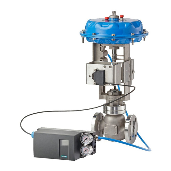
- Page 1 SIPART PS2 (6DR5...) Electropneumatic positioners SIPART PS2 with and without HART Compact Operating Instructions Edition 02/2014 Answers for industry.
- Page 3 English ······························································································· 3 Français ··························································································· 49 Deutsch ···························································································· 99 Español ··························································································· 149 Italiano ···························································································· 199 Nederlands ······················································································ 249...
-
Page 5: Legal Information
WARNING Siemens products may only be used for the applications described in the catalog and in the relevant technical documentation. If products and components from other manufacturers are used, these must be recommended or approved by Siemens. Proper transport, storage, installation, assembly, commissioning, operation and maintenance are required to ensure that the products operate safely and without any problems. -
Page 6: Checking The Consignment
● Devices/replacement parts should be returned in their original packaging. ● If the original packaging is no longer available, ensure that all shipments are properly packaged to provide sufficient protection during transport. Siemens cannot assume liability for any costs associated with transportation damages. SIPART PS2 (6DR5...) -
Page 7: Notes On Warranty
The contents of this manual shall not become part of or modify any prior or existing agreement, commitment or legal relationship. The sales contract contains all obligations on the part of Siemens as well as the complete and solely applicable warranty conditions. -
Page 8: Improper Device Modifications
● They are trained or instructed in maintenance and use of appropriate safety equipment according to the pertinent safety regulations. WARNING Unsuitable device for the hazardous area Danger of explosion. ● Only use equipment that is approved for use in the intended hazardous area and labelled accordingly. See also Technical data (Page 34) SIPART PS2 (6DR5...) A5E03436620-04, 02/2014... -
Page 9: Basic Safety Instructions
Danger of explosion in hazardous areas. ● Close the cable inlets for the electrical connections. Only use cable glands or plugs which are approved for the relevant type of protection. See also Technical data (Page 34) SIPART PS2 (6DR5...) A5E03436620-04, 02/2014... -
Page 10: Proper Mounting
You require different installation parts depending on the selected actuator type. The mounting kit is suitable for a stroke of 3 to 35 mm. For a larger stroke range, you require a separately ordered lever 6DR4004-8L. Refer to the detailed operating instructions for further information on mounting. SIPART PS2 (6DR5...) A5E03436620-04, 02/2014... -
Page 11: Mounting The Part-Turn Actuator
1. Unscrew the sintered bronze attenuator from the exhaust air opening at the bottom side of the enclosure. 2. Screw in the aforementioned gland into the exhaust air opening. 3. Install the aforementioned plastic hose into the gland and check whether it fits firmly. SIPART PS2 (6DR5...) A5E03436620-04, 02/2014... -
Page 12: Positioners Subjected To Fast Acceleration Or Strong Vibration
Locking transmission ratio to 33° Friction clutch latch ③ ⑧ Neutral position Locking friction clutch ④ ⑨ Locking transmission ratio to 90° Release friction clutch ⑤ Transmission ratio selector Figure 3-2 Locking friction clutch and transmission ratio SIPART PS2 (6DR5...) A5E03436620-04, 02/2014... -
Page 13: External Position Detection
The EMC filter module is always used for the control unit whenever an external position detection system is used instead of the internal position sensor. An external position detection system is, for example, a potentiometer with a 10 kΩ resistance or a non contacting system. SIPART PS2 (6DR5...) A5E03436620-04, 02/2014... -
Page 14: Installing Option Modules
● Connect devices in hazardous areas only in a de-energized state. Exceptions: ● Circuits of limited energy may also be connected in the energized state in hazardous areas. ● Exceptions for type of protection "Non-sparking nA" (Zone 2) are regulated in the relevant certificate SIPART PS2 (6DR5...) A5E03436620-04, 02/2014... - Page 15 ● Before taking the device into operation let the device adapt for several hours in the new environment. NOTICE Ambient temperature too high Damage to cable sheath. ● At an ambient temperature ≥ 60 °C (140 °F), use heat-resistant cables suitable for an ambient temperature at least 20 °C (68 °F) higher. SIPART PS2 (6DR5...) A5E03436620-04, 02/2014...
- Page 16 Communication with the master is still possible. The "Jumper" on the basic electronics is used to activate this function. It can be accessed after removing the module cover, and must be switched from the right position (delivery state) to the left position. SIPART PS2 (6DR5...) A5E03436620-04, 02/2014...
-
Page 17: Electric Connection
Connection diagram for order numbers 6DR52..-0N...; 6DR52.5-0E...; 6DR53..-0N...; 6DR53.5-0E... ① ③ Basic electronics HART communicator for 6DR52..-0N... and 6DR52.5-0E... only ② ④ Binary input 1 Signal source Figure 4-2 Device version 2-/3-/4-wire, with connection type 2-wire (without Ex/with Ex d) SIPART PS2 (6DR5...) A5E03436620-04, 02/2014... - Page 18 Basic device (PA) Connection diagram for order numbers 6DR55..-0N…; 6DR55.5-0E... ① ③ Basic electronics Binary input 1 ② ④ Input: Safety shutdown Power source Figure 4-4 Device version 2-wire PROFIBUS PA (without Ex/with Ex d) SIPART PS2 (6DR5...) A5E03436620-04, 02/2014...
- Page 19 Connection diagram for order numbers 6DR50..-0E/D/F/G/K...; 6DR51..-0E/D/F/G/K... ① ④ Non-hazardous area Binary input 1 ② ⑤ Potentially explosive atmosphere HART communicator for 6DR51..-0E/D/F/G/K... only ③ ⑥ Basic electronics Signal source Figure 4-6 2-wire device version (Ex i/Ex n/Ex t) SIPART PS2 (6DR5...) A5E03436620-04, 02/2014...
- Page 20 ④ Non-hazardous area Binary input 1 ② ⑤ Potentially explosive atmosphere HART communicator for 6DR52..-0E/D/F/G/K... only ③ ⑥ Basic electronics Signal source Figure 4-7 2-/3-/4-wire device version, with 2-wire connection type (Ex i/Ex n/Ex t) SIPART PS2 (6DR5...) A5E03436620-04, 02/2014...
- Page 21 Dotted connection lines: only for three-wire connection Figure 4-8 2-/3-/4-wire device version, with 3-/4-wire connection type (Ex i/Ex n/Ex t) 4.2.2.2 Split range For further information about "Split-range" operation, refer to the detailed operating instructions for your respective device version. SIPART PS2 (6DR5...) A5E03436620-04, 02/2014...
- Page 22 Connection diagram for order number 6DR56..-0E/D/F/G/K... ① ④ Non-hazardous area Input: Safety shutdown ② ⑤ Potentially explosive atmosphere Simulation enable ③ ⑥ Basic electronics Power source Figure 4-10 Device version 2-wire with FOUNDATION Fieldbus (Ex i/Ex n/Ex t) SIPART PS2 (6DR5...) A5E03436620-04, 02/2014...
-
Page 23: Pneumatic Connection On The Standard Controller
Actuating pressure Y1 for single and double-acting actuators ② Positioner axis ③ Supply air PZ ④ Actuating pressure Y2 for double-acting actuators ⑤ Exhaust air outlet with a sound absorber Figure 4-11 Pneumatic connection on the standard controller SIPART PS2 (6DR5...) A5E03436620-04, 02/2014... -
Page 24: Pneumatic Connection In The Flameproof Enclosure
● In case of double-acting valves, ensure that both restrictors have approximately the same setting. ① Restrictor Y1 ② Restrictor Y2, only in the version for double-acting actuators ③ Hexagon socket-head screw 2.5 mm Figure 4-13 Restrictors SIPART PS2 (6DR5...) A5E03436620-04, 02/2014... - Page 25 Damage to device if the enclosure is open or not properly closed. The degree of protection specified on the nameplate or in Chapter "Technical data (Page 34)" is no longer guaranteed. ● Make sure that the device is securely closed. SIPART PS2 (6DR5...) A5E03436620-04, 02/2014...
-
Page 26: Safety Notes For Operation With Natural Gas
You have to define a few parameters for the positioner before initialization. Owing to the preset values, you cannot adjust further parameters for initialization. You can use a suitably configured and activated binary input to protect the configured settings against accidental adjustment. SIPART PS2 (6DR5...) A5E03436620-04, 02/2014... -
Page 27: Sequence Of Automatic Initialization
When used the value must correspond with the set range of stroke on the actuator. Carriers must be scaled to the actuator's stroke value,or if this is not scaled they then must be set to the next largest scaled value. SIPART PS2 (6DR5...) A5E03436620-04, 02/2014... -
Page 28: Purge Air Switching
(P) in percent is shown in the upper line of the display, e.g.: "P12.3", and "NOINI" blinks in the lower line: 2. Connect the actuator and the positioner to the pneumatic lines. 3. Supply the pneumatic auxiliary power to the positioner. SIPART PS2 (6DR5...) A5E03436620-04, 02/2014... -
Page 29: Automatic Initialization Of Linear Actuators
33° or 90°. 4. Set the "3.YWAY" parameter to determine the total stroke in mm. The setting of parameter 3 is optional. The display shows the determined total stroke only at the end of the initialization phase. SIPART PS2 (6DR5...) A5E03436620-04, 02/2014... -
Page 30: Manual Initialization Of Linear Actuators
The software status is displayed. After releasing the button, the positioner is in "P manual mode". The positioner is not initialized. 5.6.3 Manual initialization of linear actuators See detailed operating instructions for information on manual initialization of linear actuators. SIPART PS2 (6DR5...) A5E03436620-04, 02/2014... -
Page 31: Preparing Part-Turn Actuators For Commissioning
An ongoing initialization can be interrupted at any time. To do this, press . The settings configured until then are retained. All parameters are reset to factory settings only if you have explicitly activated the preset settings in the "PRST" parameter. SIPART PS2 (6DR5...) A5E03436620-04, 02/2014... - Page 32 Aborting the automatic initialization process 1. Press the button. The display shows the following: The positioner is in the "Configuration" mode. 2. Exit the "Configuration" mode. To do this, press the button for at least 5 seconds. SIPART PS2 (6DR5...) A5E03436620-04, 02/2014...
-
Page 33: Manual Initialization Of Part-Turn Actuators
Service and maintenance Basic safety instructions WARNING Impermissible repair of the device ● Repair must be carried out by Siemens authorized personnel only. WARNING Impermissible accessories and spare parts Danger of explosion in areas subject to explosion hazard. ● Only use original accessories or original spare parts. -
Page 34: Cleaning Of The Screens
3. Fit the pneumatic terminal strip on both studs so that it fits flushly. 4. Screw-on the three self-tapping screws. 5. Place the cover and tighten it. 6. Reconnect the pipelines and feed the pneumatic power supply. SIPART PS2 (6DR5...) A5E03436620-04, 02/2014... -
Page 35: Return Procedure
Directive 2002/96/EC on waste electronic and electrical equipment (WEEE). They can be returned to the supplier within the EC or to a locally approved disposal service. Observe the specific regulations valid in your country. SIPART PS2 (6DR5...) A5E03436620-04, 02/2014... -
Page 36: Technical Data
Class 2 Unrestricted flow (DIN 1945) ● Inlet air valve (ventilate actuator) 2 bar (29 psi) 4.1 Nm³/h (18.1 USgpm) 4 bar (58 psi) 7.1 Nm³/h (31.3 USgpm) 6 bar (87 psi) 9.8 Nm³/h (43.1 USgpm) SIPART PS2 (6DR5...) A5E03436620-04, 02/2014... - Page 37 ● 20 mA/HART device 20 ms ● PA device 60 ms ● FF device 60 ms (min. loop time) Natural gas as actuator medium See detailed operating instructions for technical data for natural gas as actuator medium. SIPART PS2 (6DR5...) A5E03436620-04, 02/2014...
- Page 38 SIPART PS2 with and without HART 7.3.1 Electrical data Basic device without Basic device with Basic device with Basic device with explosion protection explosion protection explosion protection explosion protection Ex d Ex "ia" Ex "ic", "nA", "t" Current input I ●...
- Page 39 ● Screw terminals 2.5 AWG28-12 ● Cable gland M20x1.5 or Ex d certified M20x1.5 or M20x1.5 or ½-14 NPT M20x1.5; ½-14 NPT ½-14 NPT ½-14 NPT or M25x1.5 Connections, pneumatic Female thread G¼ or ¼-18 NPT SIPART PS2 (6DR5...) A5E03436620-04, 02/2014...
-
Page 40: Electrical Data
SIPART PS2 with PROFIBUS PA/with FOUNDATION Fieldbus 7.4.1 Electrical data Basic device without Basic device with Basic device with Basic device with explosion protection explosion protection explosion protection explosion protection Ex d Ex "ia" Ex "ic", "nA", "t" Auxiliary power supply bus... -
Page 41: Profibus Pa Communication
Response time for a master Typically, 10 ms telegram Device address 126 (in the as-delivered condition) PC parameter assignment SIMATIC PDM; supports all device objects. The software is not included in the scope of software delivery. SIPART PS2 (6DR5...) A5E03436620-04, 02/2014... -
Page 42: Foundation Fieldbus Communication
1 PID function block (PID) 1 transducer block (standard advanced positioner valve) Execution times of the blocks AO: 60 ms PID: 80 ms Physical layer profile 123, 511 FF registration Tested with ITK 5.0 Device address 22 (when delivered) SIPART PS2 (6DR5...) A5E03436620-04, 02/2014... -
Page 43: Option Modules
= negligibly small Effective internal inductance = negligibly small = negligibly small Galvanic isolation The three outputs, the BE2 input and the basic device are galvanically isolated from each other. Test voltage DC 840 V, 1 s SIPART PS2 (6DR5...) A5E03436620-04, 02/2014... -
Page 44: Sia Module
= 25 mA = DC 15 V ≥ 3 mA (limit not = 64 mW = 25 mA activated), "nA": ≤ 1 mA (limit activated) ≤ DC 15 V ≤ 64 mW SIPART PS2 (6DR5...) A5E03436620-04, 02/2014... - Page 45 ● Connection At switching amplifier in accordance with EN 60947-5- 6: (NAMUR), = 8.2 V, R = 1 kΩ). ● Signal state High R = 1.1 kΩ > 2.1 mA > 2.1 mA (not triggered) SIPART PS2 (6DR5...) A5E03436620-04, 02/2014...
-
Page 46: Emc Filter Module
≤ 0.1%/10 K (≤ 0.1%/18 °F) for -20 to 90 °C (-4 to 194 °F) rotation angle 120° or stroke ≤ 0.2%/10 K (≤ 0.2%/18 °F) for -40 to -20 °C (-40 to -4 °F) 14 mm) Climate class According to DIN EN 60721-3-4 SIPART PS2 (6DR5...) A5E03436620-04, 02/2014... - Page 47 1K5, but -40 ... +90 °C (1K5, but -40 ... +194 °F) ● Transport 2K4, but -40 ... +90 °C (2K4, but -40 ... +194 °F) ● Operation 4K3, but -40 ... +90 °C (4K3, but -40 ... +194 °F) ) Impact energy max. 1 joule. SIPART PS2 (6DR5...) A5E03436620-04, 02/2014...
- Page 48 II 3 G Ex ic IIC T6/T4 Gc Non-sparking "nA" Zone 2: II 3 G Ex nA IIC T6/T4 Gc Permissible ambient temperature T4: -40 ... +90 °C (-40 ... +194 °F) T6: -40 ... +60 °C (-40 ... +140 °F) SIPART PS2 (6DR5...) A5E03436620-04, 02/2014...
-
Page 49: Technical Support
● Information about field service, repairs, spare parts and lots more under "Services." Additional Support Please contact your local Siemens representative and offices if you have any questions about the products described in this manual and do not find the right answers. - Page 50 Trademarks All names identified by ® are registered trademarks of Siemens AG. The remaining trademarks in this publication may be trademarks whose use by third parties for their own purposes could violate the rights of the owner. Disclaimer of Liability We have reviewed the contents of this publication to ensure consistency with the hardware and software described.
-
Page 52: Get More Information
Get more information www.siemens.com/processautomation www.siemens.com/sipartps2 Siemens AG Subject to change without prior notice A5E03436620 Industry Sector A5E03436620-04 Postfach 48 48 © Siemens AG 2014 90026 NÜRNBERG GERMANY A5E03436620 www.siemens.com/automation...
Need help?
Do you have a question about the SIPART PS2 and is the answer not in the manual?
Questions and answers