Omron NJ501-1400 User Manual
Machine automation controller nj series cpu unit motion control
Hide thumbs
Also See for NJ501-1400:
- User manual (400 pages) ,
- Reference manual (990 pages) ,
- Troubleshooting manual (208 pages)

Related Manuals for Omron NJ501-1400


Summary of Contents for Omron NJ501-1400
- Page 1 Machine Automation Controller NJ-series CPU Unit Motion Control User’s Manual NJ501-1300 NJ501-1400 NJ501-1500 CPU Unit W507-E1-01...
- Page 2 OMRON. No patent liability is assumed with respect to the use of the information contained herein. Moreover, because OMRON is constantly striving to improve its high-quality products, the information contained in this manual is subject to change without notice.
-
Page 3: Introduction
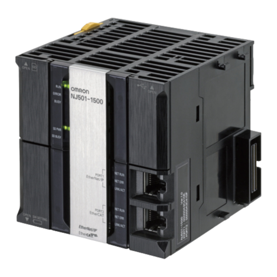
For programming, this manual is intended for personnel who understand the programming language specifications in international standard IEC 61131-3 or Japanese standard JIS B3503. Applicable Products This manual covers the following products. • NJ-series CPU Units • NJ501-1300 • NJ501-1400 • NJ501-1500 NJ-series CPU Unit Motion Control User’s Manual (W507) -
Page 4: Relevant Manuals
Relevant Manuals Relevant Manuals There are three manuals that provide basic information on the NJ-series CPU Units: the NJ-series CPU Unit Hardware User’s Manual, the NJ-series CPU Unit Software User’s Manual (this manual), and the NJ-series Instructions Reference Manual. Most operations are performed from the Sysmac Studio Automation Software. Refer to the Sysmac Stu- dio Version 1 Operation Manual (Cat. -
Page 5: Manual Configuration
Manual Configuration Manual Configuration NJ-series CPU Unit Hardware User’s Manual (Cat. No. W500) Section Description Section 1 This section provides an introduction to the NJ-series Controllers and their features, Introduction and gives the NJ-series Controller specifications. Section 2 This section describes the system configuration used for NJ-series Controllers. System Configuration Section 3 This section describes the parts and functions of the configuration devices in the NJ-... -
Page 6: Motion Control Parameters 7
Module. It includes error diagnosis and countermeasures for error indications, and Troubleshooting error diagnosis and countermeasures for operating conditions. The appendices describe settings and connection methods for OMRON G5-series Appendices Servo Drive objects. NJ-series Instructions Reference Manual (Cat. No. W502) - Page 7 Manual Configuration NJ-series CPU Unit Built-in EtherCAT Port User’s Manual (Cat. No. W505) Section Description Section 1 This section provides an overview of EtherCAT communications, describes the sys- Introduction tem configuration and specifications, and provides operating procedures. Section 2 This section provides the part names and describes the slave settings and Sysmac Part Names and Slave Settings device functions.
- Page 8 Manual Configuration Sysmac Studio Version 1 Operation Manual (Cat. No. W504) Section Description Section 1 This section provides an overview and lists the specifications of the Sysmac Studio Introduction and describes its features and components. Section 2 This section describes how to install and uninstall the Sysmac Studio. Installation and Uninstallation Section 3 This section describes the basic concepts for designing an NJ-series System with the...
-
Page 9: Manual Structure
Manual Structure Manual Structure Page Structure The following page structure is used in this manual. Level 1 heading 4 Installation and Wiring Level 2 heading Mounting Units Level 3 heading Level 2 heading Gives the current headings. Level 3 heading 4-3-1 Connecting Controller Components The Units that make up an NJ-series Controller can be connected simply by pressing the Units together... - Page 10 Manual Structure Precaution on Terminology In this manual, “download” refers to transferring data from the Sysmac Studio to the physical Controller and “upload” refers to transferring data from the physical Controller to the Sysmac Studio. For the Sysmac Studio, synchronization is used to both upload and download data. Here, “synchronize” means to automatically compare the data for the Sysmac Studio on the computer with the data in the physical Controller and transfer the data in the direction that is specified by the user.
-
Page 11: Sections In This Manual
Sections in this Manual Sections in this Manual Introduction to the Motion Control Sample Programming Function Module Motion Control Configuration and Troubleshooting Principles Configuring Axes Appendices and Axes Groups Checking Wiring from Index the Sysmac Studio Motion Control Parameters Motion Control Programming Manual Operation Homing Motion Control Functions... - Page 12 Sections in this Manual NJ-series CPU Unit Motion Control User’s Manual (W507)
-
Page 13: Table Of Contents
CONTENTS CONTENTS Introduction....................... 1 Relevant Manuals...................... 2 Manual Configuration....................3 Manual Structure ...................... 7 Sections in this Manual.................... 9 Read and Understand this Manual ................ 17 Safety Precautions ....................21 Precautions for Safe Use ..................22 Precautions for Correct Use .................. 23 Regulations and Standards ................... - Page 14 CONTENTS Section 3 Configuring Axes and Axes Groups Axes ............................3-2 3-1-1 Introduction to Axes ........................3-2 3-1-2 Introduction to Axis Parameters ....................3-3 3-1-3 Introduction to Axis Variables...................... 3-5 3-1-4 Specifying an Axis in the User Program..................3-7 Axis Setting Procedure ......................3-8 3-2-1 Axis Configuration Procedure .....................
- Page 15 CONTENTS Section 6 Motion Control Programming Introduction..........................6-2 Motion Control Instructions....................6-3 6-2-1 Function Blocks for PLCopen Motion Control ................6-3 6-2-2 Motion Control Instructions of the MC Function Module............. 6-3 State Transitions........................6-4 6-3-1 Status of the Motion Control Function Module................6-4 6-3-2 Axis States..........................
- Page 16 CONTENTS Section 9 Motion Control Functions Single-axis Position Control ....................9-3 9-1-1 Outline of Operation ........................9-3 9-1-2 Absolute Positioning........................9-4 9-1-3 Relative Positioning........................9-4 9-1-4 Interrupt Feeding......................... 9-5 9-1-5 Stopping ............................9-6 9-1-6 Override Factors.......................... 9-9 Single-axis Synchronized Control ..................9-11 9-2-1 Overview of Synchronized Control....................
- Page 17 CONTENTS 10-1-2 Installation and Wiring ......................10-2 10-1-3 Setup ............................10-3 10-2 Basic Programming Samples ....................10-4 10-2-1 Monitoring EtherCAT Communications and Turning ON Servos ..........10-4 10-2-2 Interlocking Axis Operation with Master Control Instructions ........... 10-6 10-2-3 Error Monitoring and Error Resetting for Single-axis Operation and Synchronized Operation. 10-8 10-2-4 Error Monitoring and Error Resetting for Multi-axes Coordinated Operation ......
- Page 18 CONTENTS NJ-series CPU Unit Motion Control User’s Manual (W507)
-
Page 19: Read And Understand This Manual
WHETHER SUCH CLAIM IS BASED ON CONTRACT, WARRANTY, NEGLIGENCE, OR STRICT LIABILITY. In no event shall the responsibility of OMRON for any act exceed the individual price of the product on which liability is asserted. IN NO EVENT SHALL OMRON BE RESPONSIBLE FOR WARRANTY, REPAIR, OR OTHER CLAIMS... - Page 20 Application Considerations SUITABILITY FOR USE OMRON shall not be responsible for conformity with any standards, codes, or regulations that apply to the combination of products in the customer's application or use of the products. At the customer's request, OMRON will provide applicable third party certification documents identifying ratings and limitations of use that apply to the products.
- Page 21 Performance data given in this manual is provided as a guide for the user in determining suitability and does not constitute a warranty. It may represent the result of OMRON's test conditions, and the users must correlate it to actual application requirements. Actual performance is subject to the OMRON Warranty and Limitations of Liability.
- Page 22 Read and Understand this Manual NJ-series CPU Unit Motion Control User’s Manual (W507)
-
Page 23: Safety Precautions
Safety Precautions Safety Precautions Definition of Precautionary Information Refer to the following manuals for safety precautions. • NJ-series CPU Unit Hardware User’s Manual (Cat. No. W500) • NJ-series CPU Unit Software User’s Manual (Cat. No. W501) NJ-series CPU Unit Motion Control User’s Manual (W507) -
Page 24: Precautions For Safe Use
Precautions for Safe Use Precautions for Safe Use Refer to the following manuals for precautions for safe use. • NJ-series CPU Unit Hardware User’s Manual (Cat. No. W500) • NJ-series CPU Unit Software User’s Manual (Cat. No. W501) NJ-series CPU Unit Motion Control User’s Manual (W507) -
Page 25: Precautions For Correct Use
Precautions for Correct Use Precautions for Correct Use Refer to the following manuals for precautions for correct use. • NJ-series CPU Unit Hardware User’s Manual (Cat. No. W500) • NJ-series CPU Unit Software User’s Manual (Cat. No. W501) NJ-series CPU Unit Motion Control User’s Manual (W507) -
Page 26: Regulations And Standards
Concepts EMC Directive OMRON devices that comply with EC Directives also conform to the related EMC standards so that they can be more easily built into other devices or the overall machine. The actual products have been checked for conformity to EMC standards.* Whether the products conform to the standards in the system used by the customer, however, must be checked by the customer. - Page 27 The NJ-series Controllers comply with the following shipbuilding standards. Applicability to the ship- building standards is based on certain usage conditions. It may not be possible to use the product in some locations. Contact your OMRON representative before attempting to use a Controller on a ship.
-
Page 28: Unit Versions
Gives the lot number and serial number of the Unit. serial number DDMYY: Lot number, @: For use by OMRON, xxxx: Serial number “M” gives the month (1 to 9: January to September, X: October, Y: November, Z: December) MAC address Gives the MAC address of the built-in port on the Unit. - Page 29 Unit Versions Right-click any open space in the Unit Editor and select Production Information. The Production Information Dialog Box is displayed. Simple Display Detailed Display In this example, “Ver.1.0” is displayed next to the unit model. The following items are displayed. CPU Unit CJ-series Units Unit model...
- Page 30 Unit Versions Unit Version Notation In this manual, unit versions are specified as shown in the following table. Product nameplate Notation in this manual Remarks “Ver.1.0” or later to the right of Unit version 1.0 or later Unless unit versions are specified, the information in this manual the lot number applies to all unit versions.
-
Page 31: Related Manuals
When programming, use this manual together Manual trol instructions that are with the NJ-series CPU Unit Hardware User’s provided by OMRON. Manual (Cat. No. W500), NJ-series CPU Unit Software User’s Manual (Cat. No. W501) and NJ-series CPU Unit Motion Control User’s Man- ual (Cat. - Page 32 Related Manuals Manual name Cat. No. Model numbers Application Description NJ-series CPU Unit Built- W505 NJ501-@@@@ Using the built-in EtherCAT Information on the built-in EtherCAT port is pro- in EtherCAT Port User’s port on an NJ-series CPU vided. This manual provides an introduction and Manual Unit.
-
Page 33: Revision History
Revision History Revision History A manual revision code appears as a suffix to the catalog number on the front and back covers of the manual. W507-E1-01 Cat. No. Revision code Revision code Date Revised content July 2011 Original production NJ-series CPU Unit Motion Control User’s Manual (W507) - Page 34 Revision History NJ-series CPU Unit Motion Control User’s Manual (W507)
-
Page 35: Introduction To The Motion Control Function Module
Introduction to the Motion Control Function Module This section describes the features, system configuration, and application flow for the Motion Control Function Module. 1-1 Features ........... . . 1-2 1-2 System Configuration . -
Page 36: Features
S-curve for acceleration and deceleration. Data Transmission Using EtherCAT Communications The MC Function Module can be combined with OMRON G5-series Servo Drives with built-in EtherCAT communications to enable exchange of all control information with high-speed data communications. -
Page 37: System Configuration
1 Introduction to the Motion Control Function Module System Configuration The MC Function Module receives sensor signal status from devices and control panels. It receives commands from the motion control instructions that are executed in the user program. It uses both of these to perform motion control with the Servo Drives and Encoder Input Terminals. -
Page 38: Application Procedure
1 Introduction to the Motion Control Function Module Application Procedure This section provides the basic procedure to perform motion control with the MC Function Module. Basic Flow of Operation START Sysmac Studio Version 1 Operation Manual Setup Create a project. (Cat. - Page 39 1 Introduction to the Motion Control Function Module Section 6 Motion Control Pro- Programming Write a program to perform jogging. gramming Section 7 Manual Operation Jog the axes with the user program. Manual operation Section 8 Homing Define the homes of the Servomotor axes to Homing control.
-
Page 40: Specifications
Performance Specifications Specification Item NJ501-1300 NJ501-1400 NJ501-1500 Applicable Servo Drives OMRON G5-series Servo Drives with Built-in EtherCAT Communica- tions Applicable Encoder Input Terminals OMRON GX-series GX-EC0211/EC0241 Encoder I/O Terminals*2 Control method Control commands using EtherCAT communications Control modes Position control (Cyclic Synchronous Position Control Mode) -
Page 41: Function Specifications
*3 Positions can be set to within the range of 40-bit signed integers when they are converted to pulses. 1-4-3 Function Specifications The following functions are supported when connected to an OMRON G5-series Servo Drive with built- in EtherCAT communications. Item... - Page 42 1 Introduction to the Motion Control Function Module Item Description Single Auxiliary Resetting axis errors Axis errors are cleared. axes functions Homing The motor is operated to determine the home using the limit for single- signals, home proximity signal, and home signal. axis control High-speed homing The axis returns to home using an absolute position of 0 as...
- Page 43 Absolute encoder support You can use an OMRON G5-series Servomotor with an Absolute Encoder to eliminate the need to perform homing at startup. Backlash compensation Servo Drive auxiliary functions are used.
- Page 44 1 Introduction to the Motion Control Function Module 1-10 NJ-series CPU Unit Motion Control User’s Manual (W507)
-
Page 45: Motion Control Configuration And Principles
Motion Control Configuration and Principles This section outlines the internal structure of the CPU Unit and describes the configura- tion and principles of the MC Function Module. 2-1 Internal Configuration of the CPU Unit ......2-2 2-2 Motion Control Configuration . -
Page 46: Internal Configuration Of The Cpu Unit
2 Motion Control Configuration and Principles Internal Configuration of the CPU Unit This section provides an overview of the internal mechanisms of the NJ-series CPU Unit. The CPU Unit has the following software configuration. The Motion Control Function Module is a software module that performs motion control. -
Page 47: Motion Control Configuration
2 Motion Control Configuration and Principles Motion Control Configuration A control system built with Servo Drives generally controls motor operation with a semi-closed loop. The semi-closed loop uses an encoder attached to the motor to detect the amount of rotation that has been performed by the motor in response to the command value. -
Page 48: Motion Control Principles
2 Motion Control Configuration and Principles Motion Control Principles This section provides information on the CPU Unit tasks and how they relate to motion control. 2-3-1 CPU Unit Tasks Tasks are attributes of programs that determine the execution conditions and sequence of the pro- grams. - Page 49 2 Motion Control Configuration and Principles Basic Operation of Tasks Overall Task Operation The primary periodic task and periodic tasks operate based on the task period of the primary peri- odic task (also known as the primary period). The primary periodic task includes operations such as system common processing and motion control in addition to I/O refreshing and user program exe- cution.
- Page 50 2 Motion Control Configuration and Principles Processing Processing contents User program execution • Programs assigned to tasks are executed in the order that they are assigned. Motion control • The motion control commands from the motion control instructions in the programs are executed.
-
Page 51: Example Of Task Operations For Motion Control
2 Motion Control Configuration and Principles 2-3-2 Example of Task Operations for Motion Control Motion control instructions can be used in the primary periodic task or in a priority-16 periodic task. This section provides examples of task operations. Using Motion Control Instructions in the Primary Periodic Task If high-speed motion control is required, place the motion control instructions (FB) in the primary peri- odic task. - Page 52 2 Motion Control Configuration and Principles Using Motion Control Instructions in a Priority-16 Periodic Task If high speed motion control is not required and/or your user program is too large, place motion control instructions in a priority-16 periodic task. Timing of Processing Motion control processing (MC) for the motion control instructions (FB) that are executed in the same task period as the priority-16 periodic task are performed at the same time.
- Page 53 2 Motion Control Configuration and Principles Axis Variable Update Timing Axis Variables are system-defined variables for some of the axis parameters and for the monitor information, such as the actual position and error information for the axes controlled by the MC Function Module.
- Page 54 2 Motion Control Configuration and Principles Using Motion Control Instructions in Two Different Types of Tasks If you have processes that require high-speed motion control and processes that do not require high- speed motion control for the same axis, you can place the motion control instructions (FB) both in the primary periodic task and in a priority-16 periodic task.
-
Page 55: Ethercat Communications And Motion Control
2 Motion Control Configuration and Principles EtherCAT Communications and Motion Control The MC Function Module controls Servo Drive and encoder input slaves through the PDO communica- tions of the EtherCAT Master Function Module in the CPU Unit. This section describes EtherCAT com- munications and other items related to the MC Function Module. -
Page 56: Relationship Between Ethercat Master Function Module And Mc Function Module
PDO communications. If you do, the operation of the slaves will depend on slave specifications. For OMRON slaves, SDO communications will result in errors. • If Servo Drive and encoder input terminal EtherCAT slaves are not assigned to axes variables, you must execute sequence control for them in the same way as for general-purpose Ether- CAT slaves. -
Page 57: Relationship Between Process Data Communications Cycle And Motion Control Period
2 Motion Control Configuration and Principles 2-4-3 Relationship between Process Data Communications Cycle and Motion Control Period The PLC Function Module sends motion control commands to the MC Function Module when motion control instructions are executed in the user program. The MC Function Module then performs motion control processing based on those commands and sends the results of processing as commands to the EtherCAT’s Servo Drive. - Page 58 2 Motion Control Configuration and Principles 2-14 NJ-series CPU Unit Motion Control User’s Manual (W507)
- Page 59 Configuring Axes and Axes Groups This section describes the concept of axes and axes groups, the settings for axes that are required for the MC test run function to operate on the Sysmac Studio, and the instructions for creating and configuring axes and axes groups using the Sysmac Stu- dio.
-
Page 60: Configuring Axes And Axes Groups
The following elements are related to the axes of the MC Function Module. These elements exist for each axis. The NJ501-1300 has axis parameters for 16 axes, the NJ501-1400 has axis parameters for 32 axes, and the NJ501-1500 has axis parameters for 64 axes. -
Page 61: Introduction To Axis Parameters
3 Configuring Axes and Axes Groups 3-1-2 Introduction to Axis Parameters Axis Parameters Classification Parameter name Axis Basic Axis Number Settings Axis Use Axis Type Node Address (input devices and output devices) Unit Conversion Unit of Display Settings Command Pulse Count Per Motor Rotation Work Travel Distance Per Motor Rotation Operation Settings Maximum Velocity Maximum Jog Velocity... - Page 62 3 Configuring Axes and Axes Groups Classification Parameter name Homing Settings Homing Method Home Input Signal Homing Start Direction Home Input Detection Direction Operation Selection at Positive Limit Input Operation Selection at Negative Limit Input Homing Velocity Homing Approach Velocity Homing Acceleration Homing Deceleration Homing Jerk...
-
Page 63: Introduction To Axis Variables
• OMRON G5-series Servo Drives can be set to specific node addresses by using the rotary switches on the front panels. If the rotary switches are set to 00, the node address will be determined by the settings made in the EtherCAT Editor of the Sysmac Studio. - Page 64 3 Configuring Axes and Axes Groups Examples of Axis Variable Levels and Changing Axis Variable Names _MC_AX[0] Axis Variable _MC_AX[0].Status Level that indicates the axis status _MC_AX[0].Status.Ready Variable that indicates that the axis is ready for operation _MC_AX[0].Status.Disabled Variable that indicates when the axis is disabled _MC_AX[0].Details Level that indicates the axis control status _MC_AX[0].Details.Idle...
-
Page 65: Specifying An Axis In The User Program
3 Configuring Axes and Axes Groups 3-1-4 Specifying an Axis in the User Program In the user program, an Axis Variable name is specified for the in-out variable Axis in motion control instructions. In the following example, the Axis Variable name for the axis that was added for the sys- tem-defined Axis Variable name of _MC_AX[0] has been changed to MyAxis1 in the Sysmac Studio. -
Page 66: Axis Setting Procedure
3 Configuring Axes and Axes Groups Axis Setting Procedure This section gives the procedures to set servo axes that are newly created with the Sysmac Studio. 3-2-1 Axis Configuration Procedure START Create a project. Create the EtherCAT Network Configuration. Add axes. Assign the axes. - Page 67 3 Configuring Axes and Axes Groups Creating the EtherCAT Network Configuration There are two methods to create an EtherCAT Network Configuration: online and offline. Online Method Double-click EtherCAT in the Multiview Explorer. The EtherCAT Edit Tab Page is displayed. Select Online from the Controller Menu. The Sysmac Studio goes online with the Controller. Right-click the Master Icon in the EtherCAT Tab Page and select Compare and Merge with Actual Network Configuration from the menu.
- Page 68 3 Configuring Axes and Axes Groups Offline Method Double-click EtherCAT in the Multiview Explorer. The EtherCAT Edit Tab Page is displayed. Right-click the slave to connect and select Insert from the menu. 3-10 NJ-series CPU Unit Motion Control User’s Manual (W507)
- Page 69 3 Configuring Axes and Axes Groups The slave is inserted on the display. Insert the remaining slaves. NJ-series CPU Unit Motion Control User’s Manual (W507) 3-11...
- Page 70 3 Configuring Axes and Axes Groups Adding Axes Right-click Axis Settings in the Multiview Explorer and select Axis Settings from the Add Menu. An axis is added to the Multiview Explorer. The default name for the new axis is MC_Axis000. Copying an Axis You can also add an axis by copying the axis settings for an existing axis.
- Page 71 3 Configuring Axes and Axes Groups Assigning an Axis Right-click an axis in the Multiview Explorer and select Edit from the menu. The Axis Basic Settings are displayed in the Axis Parameter Settings Tab Page. Select Servo axis in the Axis type Box. NJ-series CPU Unit Motion Control User’s Manual (W507) 3-13...
- Page 72 3 Configuring Axes and Axes Groups Select the Servo Drive to use in the Input Device Box. This setting allows you to use the EtherCAT slave Servo Drive as an axis. Setting Axis Parameters Click each of the icons in the Axis Parameter Settings Tab Page. The settings for each icon are displayed on the Axis Parameter Settings Tab Page.
- Page 73 3 Configuring Axes and Axes Groups Right-click Axis Settings in the Multiview Explorer and select Axis Setting Table to enable set- ting the axes parameters for all axes at the same time. Precautions for Correct Use Precautions for Correct Use When making operation settings such as the display unit, electronic gear (unit conversion for- mula), maximum velocity, or maximum acceleration/deceleration, be sure to use appropriate val- ues for the operating conditions of the device.
- Page 74 Select Synchronization from the Controller Menu and then click the Transfer to Controller Button. Additional Information Introduction to Servo Drive Settings The MC Function Module connects to OMRON G5-series Servo Drives with built-in EtherCAT communications. Compatible Models The applicable model numbers are R88D-KN@@@-ECT.
-
Page 75: Axes Groups
3 Configuring Axes and Axes Groups Axes Groups This section describes the axes groups of the MC Function Module. 3-3-1 Introduction to Axes Groups Use axes groups to perform complex operations on multiple axes, such as linear or circular interpola- tion. -
Page 76: Introduction To Axes Group Parameters
3 Configuring Axes and Axes Groups 3-3-2 Introduction to Axes Group Parameters Axes Group Parameters Classification Parameter name Axes Group Basic Set- Axes Group Number tings Axes Group Use Composition Composition Axes Axes Group Operation Maximum Interpolation Velocity Settings Maximum Interpolation Acceleration Maximum Interpolation Deceleration Interpolation Acceleration/Deceleration Over Interpolation Velocity Warning Value... -
Page 77: Introduction To Axes Group Variables
3 Configuring Axes and Axes Groups 3-3-3 Introduction to Axes Group Variables Axes Group Variables are system-defined variables for the setting information and the monitoring infor- mation, such as the actual position and error information, for the axes groups controlled by the MC Function Module. - Page 78 3 Configuring Axes and Axes Groups Examples of Axes Group Variable Levels and Changing Axes Group Variable Names _MC_GRP[0] Axes Group Variables _MC_GRP[0].Status Level that indicates the axes group status _MC_GRP[0].Cmd Level that indicates the axes group command values _MC_GRP[0].Cmd.Vel Variable that indicates the command interpolation velocity _MC_GRP[0].Cmd.AccDec Variable that indicates the command interpolation accelera-...
-
Page 79: Specifying An Axes Group In The User Program
3 Configuring Axes and Axes Groups 3-3-4 Specifying an Axes Group in the User Program In the user program, an axes group variable name is specified for the in-out variable AxesGroup in motion control instructions. In the following example, the Axes Group Variable name for the axes group that was added for the system-defined Axes Group Variable name of _MC_GRP[0] has been changed to MyGroup1 in the Sysmac Studio. -
Page 80: Setting Procedures For Axes Groups
3 Configuring Axes and Axes Groups Setting Procedures for Axes Groups This section gives the procedures to use the Sysmac Studio to set up an axes group. No configuration is required if you are not going to use any axes group command instructions, such as linear interpola- tion or circular interpolation. - Page 81 3 Configuring Axes and Axes Groups Adding an Axes Group Right-click Axes Group Settings in the Multiview Explorer and select Axes Group Settings from the Add Menu. An axes group is added to the Multiview Explorer. The default name for the new axes group is MC_Group000.
- Page 82 3 Configuring Axes and Axes Groups Setting Axes Group Parameters Right-click an axes group in the Multiview Explorer and select Edit from the menu. The Axes Group Basic Settings are displayed in the Axes Group Parameter Settings Tab Page. 3-24 NJ-series CPU Unit Motion Control User’s Manual (W507)
- Page 83 3 Configuring Axes and Axes Groups Select Used axes group in the Axes group use Box. Select the composition of the axes group in the Composition Box. A 2-axis composition is selected in the following example. Assign the axis to use in the Logical axes Box. NJ-series CPU Unit Motion Control User’s Manual (W507) 3-25...
- Page 84 3 Configuring Axes and Axes Groups Click the bottom icon. The Axes Group Operation Settings Tab Page is displayed. Set appropriate values for the settings based on the operating conditions of the device. Additional Information Changing Axes Group Variable Names in the User Program Perform the following two procedures to change Axes Group Variable names that are already used.
- Page 85 3 Configuring Axes and Axes Groups Downloading to the CPU Unit Use the Synchronization menu command of the Sysmac Studio to download the project to the CPU Unit. Select Online from the Controller Menu. The Sysmac Studio goes online with the Controller. Select Synchronization from the Controller Menu and then click the Transfer to Controller Button.
- Page 86 3 Configuring Axes and Axes Groups 3-28 NJ-series CPU Unit Motion Control User’s Manual (W507)
-
Page 87: Checking Wiring From The Sysmac Studio
Checking Wiring from the Sysmac Studio This section describes the MC Test Run operations of the Sysmac Studio. You can use the MC Test Run to monitor sensor signals, check Servomotor wiring, and more, all without any programming. 4-1 Functions of the Sysmac Studio ....... . . 4-2 4-1-1 MC Test Run Function . -
Page 88: Functions Of The Sysmac Studio
4 Checking Wiring from the Sysmac Studio Functions of the Sysmac Studio This section describes how to use the MC test run function to check wiring and basic settings. You can use the MC test run function in the Sysmac Studio to check wiring without any programming. 4-1-1 MC Test Run Function The MC test run operation supports the following functions. - Page 89 For details, refer to the MC_MoveAbsolute (Absolute Positioning) instruction in the NJ-series Motion Control Instructions Reference Manual (Cat. No. W508). Note This MC Test Run is used for an OMRON G5-series Servo Drive with built-in EtherCAT communications. Do not use it with servo drives from any other manufacturer.
-
Page 90: Application Procedure
4 Checking Wiring from the Sysmac Studio 4-1-2 Application Procedure Before you perform an MC Test Run, check the following two items. • Are the Sysmac Studio and Controller connected and are they online? • Is the MC Test Run Mode currently in use from any other copy of the Sysmac Studio? After you have confirmed these two items, perform the following operations as instructed. -
Page 91: Axis Parameter Setting Example
4 Checking Wiring from the Sysmac Studio 4-1-3 Axis Parameter Setting Example Set the following axis parameters before you execute the MC Test Run Mode in the Sysmac Studio. The following setting example is for a one-axis device. Servomotor Encoder resolution: 20 bits/rotation 1 rotation 10 mm Ball screw... -
Page 92: Starting The Mc Test Run Function
4 Checking Wiring from the Sysmac Studio 4-1-4 Starting the MC Test Run Function The MC Test Run Mode is started from the Sysmac Studio. Start the Sysmac Studio and open a project in which the axis settings are completed. Select Online from the Controller Menu. -
Page 93: Monitoring Sensor Signals
4 Checking Wiring from the Sysmac Studio Monitoring Sensor Signals You can use the input signal display to check sensor signal wiring. Select the axis to check on the MC Test Run Tab Page. Check to see if the signals turn ON and OFF properly on the monitor screen by turning ON and OFF the sensor connected to each input signal. -
Page 94: Checking Motor Operation
4 Checking Wiring from the Sysmac Studio Checking Motor Operation Use the functions of the MC Test Run to check motor operation. 4-3-1 Turning ON the Servo You can use the Servo ON Button to turn the Servo ON and OFF. Select the axis for which to turn ON the Servo. -
Page 95: Homing
4 Checking Wiring from the Sysmac Studio 4-3-3 Homing Set the homing parameters in the Homing Settings on the Axis Parameter Settings Tab Page. Click the Homing Tab on the MC Test Run Tab Page. The following dialog box is displayed. Select the axis to home. -
Page 96: Absolute Positioning
4 Checking Wiring from the Sysmac Studio 4-3-4 Absolute Positioning Click the Absolute positioning Tab on the MC Test Run Tab Page. The following dialog box will appear. Select the axis to perform absolute positioning. Click the Servo ON Button to turn ON the Servo. Enter the target position, target velocity, acceleration rate, deceleration rate, and jerk, and then click the Apply Button. -
Page 97: Relative Positioning
4 Checking Wiring from the Sysmac Studio 4-3-5 Relative Positioning Click the Relative positioning Tab on the MC Test Run Tab Page. The following dialog box will appear. Select the axis to perform relative positioning. Click the Servo ON Button to turn ON the Servo. Enter the target travel distance, target velocity, acceleration rate, deceleration rate, and jerk, and then click the Apply Button. - Page 98 4 Checking Wiring from the Sysmac Studio 4-12 NJ-series CPU Unit Motion Control User’s Manual (W507)
-
Page 99: Motion Control Parameters
Motion Control Parameters This section explains about axis parameters and axes group parameters used for motion control. 5-1 Introduction ..........5-2 5-2 Axis Parameters . -
Page 100: Introduction
5 Motion Control Parameters Introduction You can use motion control instructions to perform single-axis operations and multi-axis operations on axes groups with the NJ-series CPU Unit’s MC Function Module. Axis and axes group parameters are used to set these operations. Axis parameters must be set, but axes group parameters are not required if you do not use multi-axis operations for axes groups. - Page 101 5 Motion Control Parameters • For details on the MC_Write (Write MC Setting) instruction, refer to the NJ-series Motion Instruc- tions Reference Manual (Cat. No. W508). Precautions for Correct Use Precautions for Correct Use • Changes made using the MC_Write (Write MC Setting) instruction will not be saved to non- volatile memory in the CPU Unit.
-
Page 102: Axis Parameters
MC Function Module. There are axis parameters for each axis. The NJ501-1300 has axis parame- ters for 16 axes, the NJ501-1400 has axis parameters for 32 axes, and the NJ501-1500 has axis parameters for 64 axes. The same parameter settings are provided for each axis. This section describes only the parameters for axis 1. -
Page 103: Axis Basic Settings
5 Motion Control Parameters Temporary Reading Classification Parameter name Page changes variables Position Count Count Mode 5-13 Settings Modulo Maximum Position Setting Value Modulo Minimum Position Setting Value Encoder Type Servo Drive Modulo Maximum Position Setting Value 5-15 Settings Modulo Minimum Position Setting Value Homing Set- Homing Method 5-16... - Page 104 *1 The applicable Servo Drives are the OMRON G5-series Servo Drives with Built-in EtherCAT Communications. *2 The applicable Encoder Input Terminals are the OMRON GX-series GX-EC0211/EC0241 Encoder I/O Termi- nals.
- Page 105 Precautions for Correct Use Precautions for Correct Use • OMRON G5-series Servo Drives can be set to specific node addresses by using the node address switches on the front panels. If the node address switches are set to 00, the node address will be determined by the settings made in the EtherCAT Editor of the Sysmac Studio.
-
Page 106: Unit Conversion Settings
ON. • An error occurs if the same node address is used more than once. • The value set from the Sysmac Studio will be used for all non-OMRON slaves, regardless of any setting at the slave. - Page 107 5 Motion Control Parameters Unit Description Use this unit for more precise direct operation than µm. degree Use this unit for rotary tables or other rotating axes. inch Use this unit for direct operation. NJ-series CPU Unit Motion Control User’s Manual (W507)
- Page 108 40 bits. Setting Example In this example, an OMRON G5-series Servomotor with a 17-bit absolute encoder is used. The reduction ratio of the reducer is 1/5 and the workpiece moves 10 mm for every rotation of the ball screw.
-
Page 109: Operation Settings
5 Motion Control Parameters Additional Information Parameter Settings for a Reduction Ratio of 1/9 for the Setting Example The travel distance of the workpiece for one rotation of the Servomotor is 10 mm × 1/9, or 1.1111... mm (a repeating decimal number). For numbers that do not divide evenly, multiply the command pulse count per motor rotation and the work travel distance per motor rotation by the same coefficient and set the parameters to the results. -
Page 110: Other Operation Settings
5 Motion Control Parameters Parameter name Function Setting range Default Deceleration Warn- Set the percentage of the maximum decelera- 0 to 100 ing Value tion rate at which to output a deceleration warning for the axis. No deceleration warning is output if 0 is set. (Unit: %) Positive Torque Set the torque command value at which to out- 0 to 1,000... -
Page 111: Limit Settings
5 Motion Control Parameters Parameter name Function Setting range Default Maximum Positive 0.0 to 1000.0 300.0 Set the maximum value of the positive torque limit. Torque Limit (Unit: %) Maximum Negative 0.0 to 1000.0 300.0 Set the maximum value of the negative torque limit. Torque Limit (Unit: %) * If Positive Torque Limit (60E0 hex) and Negative Torque Limit (60E1 hex) are mapped as PDOs, the set values of... - Page 112 5 Motion Control Parameters Count Modes The Count Mode is the feed mode for the axis. Select the count mode for the command positions for each axis. There are two Count Modes: Linear Mode, which has a finite axis feed range and Rotary Mode, which has an infinite axis feed range.
-
Page 113: Servo Drive Settings
−2 −1 to 2 Setting Value ting value on the Servo Drive. * The default range is all DINT integers. You can use the default range with OMRON G5-series Servo Drives. NJ-series CPU Unit Motion Control User’s Manual (W507) 5-15... -
Page 114: Homing Settings
5 Motion Control Parameters 5-2-9 Homing Settings Set the motor operation to use to determine home. Parameter name Function Setting range Default Set the homing operation. 0, 1, 4, 5, 8, 9, or Homing Method 11 to 14 0: Proximity reverse turn/home proximity input OFF 1: Proximity reverse turn/home proximity input ON 4: Home proximity input OFF 5: Home proximity input ON... -
Page 115: 5-2-10 Axis Parameter Setting Example
OMRON G5-series Servo Drives, the external home input is allocated to latch 1. The allo- cation of latch 1 can be changed using a servo parameter object in the Servo Drive. Refer to the OMRON G5- series AC Servomotors/Servo Drives with Built-in EtherCAT Communications User's Manual (Cat. - Page 116 5 Motion Control Parameters Settings Parameter name Axis 1 Axis 2 Software Limits Immediate stop for command posi- Immediate stop for command posi- tion tion Positive Software Limit 500,000 500,000 Negative Software Limit Count Mode Linear Mode Linear Mode *1 The position command unit will be 1 µm. *2 The maximum velocity will be 3,000 r/min = 30 m/min = 0.5 m/s = 500,000 µm/s.
- Page 117 5 Motion Control Parameters Settings Parameter name Axis 1 Axis 2 Positive Software Limit 500,000 Negative Software Limit Count Mode Linear Mode Rotary Mode Modulo Maximum Position 1,000,000 Modulo Minimum Position *1 The position command unit will be 1 µm. *2 The maximum velocity will be 3,000 r/min = 30 m/min = 0.5 m/s = 500,000 µm/s.
-
Page 118: Axes Group Parameters
5 Motion Control Parameters Axes Group Parameters Use the axes group parameters to set axes group operations related to axes groups that the MC Func- tion Module controls, such as the axis configuration, maximum interpolation velocity, and axes group stopping method. There are axes group parameters for each of 32 groups for the NJ501-1300, NJ501- 1400, or NJ501-1500. -
Page 119: Axes Group Basic Settings
5 Motion Control Parameters 5-3-2 Axes Group Basic Settings Set whether to use the axes group. If you are going to use the axes group, set the axis configuration and the axes to use. Parameter name Function Setting range Default Axes Group Use Set whether to enable or disable the axes group. -
Page 120: Axes Group Operation Settings
5 Motion Control Parameters Composition Axes Setting Examples • Example 1: Assigning Four Axes with Axis Numbers 1, 2, 5, and 8 to an Axes Group Logical axis Axis number Axis A0 Axis 1 Axis A1 Axis 2 Axis A2 Axis 5 Axis A3 Axis 8... -
Page 121: Enabling An Axes Group
5 Motion Control Parameters Parameter name Function Setting range Default Interpolation Accel- Set the percentage of the maximum interpo- 0 to 100 eration Warning lation acceleration at which to output an Value interpolation acceleration warning. No inter- polation acceleration warning is output if 0 is set. - Page 122 5 Motion Control Parameters 5-24 NJ-series CPU Unit Motion Control User’s Manual (W507)
-
Page 123: Motion Control Programming
Motion Control Programming This section provides the specifications of a motion control program and the operation procedures that are required up through actual program development. 6-1 Introduction ..........6-2 6-2 Motion Control Instructions . -
Page 124: Introduction
6 Motion Control Programming Introduction The NJ-series CPU Unit can perform both sequence control and motion control. Write motion control instructions into the user program to perform motion control with EtherCAT slave Servo Drives and other devices. Programs that contain motion control instructions are called motion control programs. CPU Unit User program in PLC Function Module... -
Page 125: Motion Control Instructions
6 Motion Control Programming Motion Control Instructions Motion control instructions are used in the user program to execute motion controls for an NJ-series Controller. These instructions are defined as function blocks (FBs). The motion control instructions of the MC Function Module are based on the technical specifications of function blocks for PLCopen motion control. -
Page 126: State Transitions
6 Motion Control Programming State Transitions The states of axes and axes groups and state transitions caused by the execution of instructions are based on the technical specifications of function blocks for PLCopen motion control. This section pro- vides an overall description of the MC Function Module, states, and state transitions. 6-3-1 Status of the Motion Control Function Module The overall states of the MC Function Module are described in the following table. - Page 127 6 Motion Control Programming *1 Transition into this state occurs when there is an axis error in any state except for Coordinated Motion state. *2 Transition into this state occurs when there are no axis errors and the Status output to the MC_Power instruc- tion is FALSE.
-
Page 128: Axes Group States
6 Motion Control Programming 6-3-3 Axes Group States The operation of an axes group when motion control instructions are executed for it is shown in the fol- lowing figure. Moving Moving MC_GroupStop Deceleration Stopping Stopping MC_GroupImmediateStop Error Deceleration Stopping ErrorStop MC_GroupEnable Stopped Axes Group Disabled... - Page 129 6 Motion Control Programming State name Definition Group Standby In this state, no instructions for axes group commands are executing. (This is independent of the Servo ON/OFF status of the composition axes in the axes group) Moving In this state, positioning is performed for the specified target position due to a motion instruction for an axes group command.
-
Page 130: Execution And Status Of Motion Control Instructions
6 Motion Control Programming Execution and Status of Motion Control Instructions Variables that represent the execution status of instructions and variables that are used to execute motion control instructions are defined in the MC Function Module. There are two input variables that you use to execute motion control instruction functions: Execute and Enable. - Page 131 6 Motion Control Programming Item Rule There are two output variables that represent an error when a problem occurs during the Error processing execution of an instruction instance. These outputs are defined as follows: • Error: The output variable Error changes to TRUE to indicate that an error occurred during the execution of the instruction instance.
-
Page 132: Execution Timing Charts
6 Motion Control Programming Precautions for Correct Use Precautions for Correct Use • Confirm that EtherCAT process data communications are active and normal before you exe- cute motion control instructions. Refer to 10-2-1 Monitoring EtherCAT Communications and Turning ON Servos for details. •... - Page 133 6 Motion Control Programming Execute Busy Done CommandAborted Error • The following timing chart is for when the instruction is interrupted during execution while input vari- able Execute is TRUE. Execute Busy Done CommandAborted Error • The following timing chart is for when the input variable Execute is TRUE for only one period and an error does not occur for the instruction.
-
Page 134: Timing Chart For Re-Execution Of Motion Control Instructions
6 Motion Control Programming Timing Charts for Enable-type Instructions • The following timing chart is for when the input variable Enable changes to TRUE and an error does not occur for the instruction. Enable Enabled Busy Error • The following timing chart is for when the input variable Enable changes to TRUE and an error occurs for the instruction. -
Page 135: Timing Chart For Multi-Execution Of Motion Control Instructions
6 Motion Control Programming For details on re-executing instructions for the MC Function Module, refer to 9-5-6 Re-executing Motion Control Instructions and 9-7-4 Re-executing Motion Control Instructions for Multi-axes Coordinated Control. 6-4-4 Timing Chart for Multi-execution of Motion Control Instructions Another instance can be executed for an axis during axis motion. -
Page 136: Positions
6 Motion Control Programming Positions This section describes the positions that are used in motion control programming. 6-5-1 Types of Positions The MC Function Modules uses the following two types of positions. Type of position Definition Command position This is the position that the MC Function Module outputs to control an axis. Actual position The actual position as input from the Servo Drive or encoder input. -
Page 137: System-Defined Variables For Motion Control
6 Motion Control Programming System-defined Variables for Motion Control This section describes the variables of the MC Function Module. 6-6-1 Overview of System-defined Variables for Motion Control The NJ-series Controller is compliant with the IEC 61131-3 standard. Parameter settings, status information, and other data are handled as variables in the user program in the NJ-series Controller. - Page 138 6 Motion Control Programming Data Types Used for System-defined Variables for Motion Control System-defined variables for motion control use both basic data types and derivative data types. Basic Data Types Category Data type Size Range of values Notation Boolean BOOL TRUE or FALSE TRUE or FALSE Integer...
-
Page 139: System For System-Defined Variables For Motion Control
6 Motion Control Programming Derivative Data Types Type Description Enumerated data types This data type uses one item from a prepared name list as its value. Variables with this data type start with “_e.” Structure data type This data type consists of multiple data types placed together into a single layered structure. -
Page 140: Tables Of System-Defined Variables For Motion Control
6 Motion Control Programming 6-6-3 Tables of System-defined Variables for Motion Control This section provides tables that describe the system-defined variables for motion control. MC Common Variable The variable name _MC_COM is used for the MC Common Variable. The data type is _sCOMMON_REF, which is a structure variable. - Page 141 6 Motion Control Programming Axis Variables _MC_AX[0] to _MC_AX[63] are the Axis Variables in the system-defined variables. The data type is _sAXIS_REF, which is a structure variable. This section describes the configuration of the Axis Vari- ables and provides details on the members. Variable name Data type Meaning...
- Page 142 6 Motion Control Programming Variable name Data type Meaning Function Details _sAXIS_REF_DET Axis Control Status Gives the control status of the command. Idle BOOL Standstill TRUE when processing is not currently performed for the command value, except when waiting for in-position state.
- Page 143 6 Motion Control Programming Variable name Data type Meaning Function _sAXIS_REF_CMD Axis Command Values _DATA LREAL Command Current Contains the current value of the command posi- Position tion. (Unit: command units) When the Servo is OFF and the mode is not posi- tion control mode, this variable contains the actual current position.
- Page 144 6 Motion Control Programming Variable name Data type Meaning Function MFaultLvl _sMC_REF_EVENT Axis Minor Fault Active BOOL Axis Minor Fault TRUE while there is an axis minor fault. Occurrence Code WORD MC Common Minor Contains the code for an axis minor fault. Fault Code The upper four digits of the event code have the same value.
- Page 145 6 Motion Control Programming Relationship between Axis Variables and Axis Types Axis Variables are enabled or disabled according to the axis type. Disabled members are FALSE or The following table shows which members are enabled for each axis type. Virtual Virtual Servo Encoder...
- Page 146 6 Motion Control Programming Virtual Virtual Servo Encoder Variable name Data type Meaning servo encoder axis axis axis axis _sAXIS_REF_CMD_DATA Axis Command Values LREAL Command Current Enabled Enabled Position LREAL Command Current Enabled Enabled Velocity AccDec LREAL Command Current Enabled Enabled Acceleration/Decelera- tion...
- Page 147 6 Motion Control Programming Axes Group Variables _MC_GRP[0..31] are the system-defined Axes Group Variables. The data type is _sGROUP_REF, which is a structure. This section describes the configuration of the Axes Group Variables and provides details on the members. Variable name Data type Meaning Function...
- Page 148 6 Motion Control Programming Variable name Data type Meaning Function _sGROUP_REF_CMD_ Axes Group Command DATA Values LREAL Command Contains the current value of the command Interpolation Velocity interpolation velocity. The interpolation veloc- ity is calculated from the difference with the interpolation command current position.
- Page 149 6 Motion Control Programming Variable name Data type Meaning Function _sGROUP_REF_CFG Axes Group Basic Gives the settings of the Axes Group Basic Settings Settings parameters. GrpNo UINT Axes Group Number Contains the logical number of the axes group. This number is accessed to recognize the axes group number when accessing _sGROUP_REF.
-
Page 150: Cam Tables And Cam Data Variables
6 Motion Control Programming Cam Tables and Cam Data Variables The MC Function Module uses the cam profile curves that you create on the Cam Editor of the Sysmac Studio as cam tables. The cam table data is handled as cam data variables in the user program in the NJ-series Controller. - Page 151 6 Motion Control Programming Precautions for Correct Use Precautions for Correct Use • If you change any cam data in the user program, those changes are lost and the cam table in non-volatile memory is restored if you restart the power or download cam data from the Sys- mac Studio.
- Page 152 6 Motion Control Programming Precautions for Correct Use Precautions for Correct Use • Synchronize the data with the Controller before you transfer a cam table from a file to the Con- troller. • If you transfer the cam table to the Controller during a synchronization operation after you transfer a cam table from a file to the Controller, the cam table in the Controller is replaced with the data in the Cam Data Settings.
- Page 153 6 Motion Control Programming Cam Profile Curve Names When a cam profile is created in the Sysmac Studio, CamProfile0 is used as the default name. Each time you create another cam profile, the number on the end of the name is incremented. You can change the name of any cam profile as required from the Sysmac Studio.
-
Page 154: Programming Motion Controls
6 Motion Control Programming Programming Motion Controls Place motion control instructions in the user program of the NJ-series Controller to perform motion con- trol. Programs that contain motion control instructions are called motion control programs. Precautions for Correct Use Precautions for Correct Use •... - Page 155 6 Motion Control Programming Select the required instructions from the Toolbox and enter the program. Refer to the NJ-series CPU Unit Software User's Manual (Cat. No. W501) for details on programming. Refer to the Sysmac Studio Version 1 Operation Manual (Cat. No. W504) for specific procedures. NJ-series CPU Unit Motion Control User’s Manual (W507) 6-33...
-
Page 156: Creating Cam Tables
6 Motion Control Programming Creating Cam Tables This section will explain how to use the Cam Editor of the Sysmac Studio to create a cam table. Refer to the Sysmac Studio Version 1 Operation Manual (Cat. No. W504) for details on the Cam Editor. Adding a Cam Profile Right-click Cam Data Settings in the Multiview Explorer and select Cam Profile (NJ Series) from the Add Menu. - Page 157 6 Motion Control Programming The Cam Profile Edit Tab Page is displayed. Make the settings and enter the cam profile. Refer to the Sysmac Studio Version 1 Operation Manual (Cat. No. W504) for specific proce- dures. NJ-series CPU Unit Motion Control User’s Manual (W507) 6-35...
- Page 158 6 Motion Control Programming 6-36 NJ-series CPU Unit Motion Control User’s Manual (W507)
-
Page 159: Manual Operation
This section describes manual operation when the MC Function Module is used together with an OMRON G5-series Servo Drive. 7-1 Outline ............7-2 7-2 Turning ON the Servo . -
Page 160: Outline
7 Manual Operation Outline This section describes how to combine the MC Function Module and OMRON G5-series Servo Drives together and use motion control instructions from the user program to perform manual operations. The motion control instructions for manual operation are MC_Power and MC_MoveJog. MC_Power changes the Servo Drive to the Servo ON state and MC_MoveJog performs jogging. -
Page 161: Turning On The Servo
If you change Enable to FALSE while the axis is moving, the command stops immediately and all motion control instructions for that axis are disabled. Additional Information If an OMRON G5-series Servomotor with an absolute encoder is used, home is defined when Enable changes to TRUE. 7-2-1... -
Page 162: Setting Axis Parameters
Additional Information If the OMRON G5-series Servo Drive is connected properly, you can use the network scan func- tion of the Sysmac Studio to automatically set all axis parameters not listed in the previous table. -
Page 163: Setting Axis Parameters
7 Manual Operation Jogging Use the motion control instruction MC_MoveJog for jogging. Instance name Body name MC_MoveJog_instance In-out variable MC_MoveJog Axis1 Axis Axis Axis1 PositiveEnable Busy NegativeEnable CommandAborted Velocity Error Acceleration ErrorID Deceleration Input variables Output variables Specify the axis to jog with the Axis in-out variable. Change the PositiveEnable input variable to TRUE to start the axis with the specified positive Velocity (Target Velocity) and Acceleration (Acceleration Rate). -
Page 164: Setting Axis Parameters
7 Manual Operation 7-3-2 Setting Axis Parameters Set the following axis parameters if you want to jog when home is not defined. The following setting example is for a one-axis device. Servomotor Encoder resolution: 20 bits/rotation 1 rotation 10 mm Ball screw Ball screw pitch: 10 mm Encoder output pulses per motor rotation... -
Page 165: Programming Example
7 Manual Operation 7-3-4 Programming Example The following programming example jogs an axis named Axis1 in the positive direction for the value of bit A and in the negative direction for the value of bit B. MC_MoveJog_instance MC_MoveJog Axis1 Axis Axis PositiveEnable Busy... - Page 166 7 Manual Operation NJ-series CPU Unit Motion Control User’s Manual (W507)
- Page 167 Homing This section describes homing. 8-1 Outline ............8-2 8-2 Homing Procedure .
-
Page 168: Outline
• The control state of EtherCAT communications is not Operational state. Additional Information If you are using an OMRON G5-series Servomotor with an absolute encoder, home is defined when the MC_Power input variable Enable changes to TRUE. NJ-series CPU Unit Motion Control User’s Manual (W507) - Page 169 8 Homing The MC_MoveZeroPosition (High-speed Home) instruction is also provided to perform positioning to home as defined for this method. Name Description High-speed Homing The axis returns to home using an absolute position of 0 as the target position. The MC Function Module can operate the motor even when home is undefined (excluding MC_MoveZeroPosition).
- Page 170 8 Homing Precautions for Correct Use Precautions for Correct Use • For a virtual axis, home is always defined with a zero position preset. The setting of the Hom- ing Method axis parameter is ignored. • The positive drive prohibit input (POT), negative drive prohibit input (NOT), and home proxim- ity input (DEC) of the Servo Drive are used by the MC Function Module as the positive limit input, negative limit input, and home proximity input.
-
Page 171: Homing Procedure
8 Homing Homing Procedure This section describes the procedure to perform homing. Adding and Setting an Axis Add and set an axis from the Sysmac Studio. Setting Axis Parameters Set the homing method with the homing parameters. Writing the User Program Create the user program from the Sysmac Studio. - Page 172 8 Homing Parameter name Description Homing Holding Time Set the holding time when you set the Homing Operation Mode to the proximity reverse turn and holding time specification. (Unit: ms) Homing Compensation Value Set the homing compensation value that is applied after the home is defined.
- Page 173 8 Homing Homing Start Direction Set the start direction for when homing is started. To describe the relationship between the home input detection direction and the definition pattern, we will use the proximity reverse turn with home proximity input OFF specification. The difference in operation when the homing start direction and the home input detection direction are the same and when they are not the same is shown below.
- Page 174 8 Homing Home Input Detection Direction Set the home input detection direction. Refer to Homing Start Direction on page 8-7 for details on the relationship between the homing start direction and the home detection method. Homing Holding Time Set the holding time when you set the Homing Method to the proximity reverse turn and holding time specification.
- Page 175 Precautions for Correct Use Precautions for Correct Use This parameter can be used to set a home input signal only when you are connected to an OMRON G5-series Servo Drive. NJ-series CPU Unit Motion Control User’s Manual (W507)
-
Page 176: Monitoring The Homing Operation
8 Homing 8-2-2 Monitoring the Homing Operation You can read Axis Variables in the user program to monitor the homing status and the input signal sta- tus. Data Variable name Meaning Function type _MC_AX[0-63].Status.Homing BOOL Homing TRUE when homing for the MC_Home instruction. -
Page 177: Homing Operation
8 Homing Homing Operation Select the home definition method based on the configuration of the positioning system and its pur- pose. There are 10 Homing Operation Modes supported by the MC Function Module. You can also fine- tune the home that is detected with a homing compensation value. Additional Information •... -
Page 178: Homing With An Absolute Encoder
8 Homing Homing with an Absolute Encoder This section describes how to use the absolute encoder of the G5-series Servo Drive with built-in Ether- Cat communications. Servo Drives that use EtherCAT communications have their own position control loop. Therefore, the actual position from the encoder is not used in the MC Function Module for control. -
Page 179: Outline Of Function
This section describes the procedure to set the home of an absolute encoder system. Absolute Encoder Setup Refer to the OMRON G5-series AC Servomotors/Servo Drives with Built-in EtherCAT Communi- cations User's Manual (Cat. No. I576) for the setup procedure. Setting Axis Parameters Set encoder type for the Count Mode axis parameter of the MC Function Module. - Page 180 Precautions for Correct Use Precautions for Correct Use After the absolute encoder is set up, the power supply to the OMRON G5-series Servo Drive must be cycled. When setup processing for the absolute encoder is completed, an Absolute Value Clear Error (A27.1) will occur in the Servo Drive. Cycle the control power supply to the Servo Drive to clear this error and complete the absolute encoder setup procedure.
-
Page 181: High-Speed Homing
8 Homing High-speed Homing This function performs quick positioning to the home. Home is defined in advance. Use the MC_MoveZeroPosition (High-speed Homing) instruction and specify the target velocity, acceleration rate, deceleration rate, and jerk. If you execute this instruction when home is not defined an instruction error will occur. - Page 182 8 Homing 8-16 NJ-series CPU Unit Motion Control User’s Manual (W507)
-
Page 183: Motion Control Functions
This section describes the motion control functions that are used when connected to OMRON G5-series Servo Drives with built-in EtherCAT communications. 9-1 Single-axis Position Control ........9-3 9-1-1 Outline of Operation . - Page 184 9 Motion Control Functions 9-6-3 Circular Interpolation ..........9-49 9-6-4 Stopping Under Multi-axes Coordinated Control .
-
Page 185: Single-Axis Position Control
9 Motion Control Functions Single-axis Position Control The MC Function Module can be connected to OMRON G5-series Servo Drives with built-in EtherCAT communications to implement position control, velocity control, and torque control. This section describes positioning operation for single axes. -
Page 186: Absolute Positioning
9 Motion Control Functions 9-1-2 Absolute Positioning Absolute positioning specifies the absolute coordinates of the target position in relation to home. You can perform positioning, such as shortest way positioning on a rotary table, by setting the Count Mode to Rotary Mode and specifying the operation direction. Velocity Target Deceleration... -
Page 187: Interrupt Feeding
9 Motion Control Functions 9-1-4 Interrupt Feeding Interrupt feeding feeds the axis at the specified velocity and for the specified distance from the actual position when a trigger signal occurs. You can also select to output an error if the trigger signal does not occur within the specified travel distance when you specify either absolute or relative travel. -
Page 188: Stopping
Precautions for Correct Use Precautions for Correct Use The immediate stop input for the OMRON G5-series Servo Drive also causes an error and exe- cutes stop processes in the Servo Drive itself. Limit Inputs (Positive Limit Input or Negative Limit Input) Stop processing in the MC Function Module is executed according to the state of the Servo Drive input signals. - Page 189 9 Motion Control Functions Stopping with Motion Control Instructions Use the MC_Stop or MC_ImmediateStop instruction to stop single-axis operation. MC_Stop Instruction You can specify the deceleration rate and jerk for single-axis control and synchronized control to decelerate to a stop. Specify a deceleration rate of 0 to send a command that immediately stops the Servo Drive.
- Page 190 9 Motion Control Functions Stopping Due to End of MC Test Run All axes will decelerate to a stop at their maximum deceleration if a MC Test Run is stopped from the Sysmac Studio. • Click the Stop MC Test Run Button on the MC Test Run Tab Page of the Sysmac Studio. •...
-
Page 191: Override Factors
9 Motion Control Functions • Immediate Stop and Error Reset Velocity The actual position when the cause of the immediate stop occurred is used as the command position. Inertia will take the axis past this position, but it will return to the actual position when the cause of the immediate stop occurred and stop there. - Page 192 9 Motion Control Functions Overriding the MC_MoveAbsolute Instruction An example of a time chart for using the Set Override Factors instruction for the MC_MoveAbsolute (Absolute Positioning) instruction is given below. Previous Instruction: MC_MoveAbsolute Execute Busy Active Done CommandAborted Current Instruction Enable Enabled Busy...
-
Page 193: Single-Axis Synchronized Control
9 Motion Control Functions Single-axis Synchronized Control This section describes the operation of synchronized control for single axes. 9-2-1 Overview of Synchronized Control Synchronous control synchronizes the position of a slave axis with the position of a master axis. The command position or actual position of any axis can be specified for the master axis. -
Page 194: Positioning Gear Operation
9 Motion Control Functions 9-2-3 Positioning Gear Operation This function specifies the gear ratio between the master axis and the slave axis and starts operation. Positioning gear operation allows you to set the positions of the master and slave axes at which to start synchronization. -
Page 195: Cam Operation
9 Motion Control Functions 9-2-4 Cam Operation Cam operation synchronizes the position of the slave axis with the master axis according to a cam table. Start cam operation with the MC_CamIn (Start Cam Operation) instruction. End cam operation with the MC_CamOut (End Cam Operation) instruction or the MC_Stop instruction. Create a cam table using the Cam Editor in the Sysmac Studio and download it to the CPU Unit. -
Page 196: Cam Tables
9 Motion Control Functions 9-2-5 Cam Tables This section describes the cam tables that are used for cam operation. Cam Table Terminology Term Description cam operation An operation that takes one master axis and one slave axis and follows the cam profile curve to derive the displacement of the slave axis from the phase of the master axis. - Page 197 9 Motion Control Functions Term Description cam table start position The absolute position of the master axis that corresponds to the cam start point (phase = 0). master sync start posi- The master start distance where the slave axis starts cam operation represented as tion either an absolute position or relative position.
- Page 198 9 Motion Control Functions Command position during 1 cycle cam operation Cam table The phase is calculated from the master axis position each cycle. The linear Phase Displacement Cam data index interpolation of cam data is used to Cam start point calculate the displacement from the phase.
- Page 199 9 Motion Control Functions Data Type of Cam Tables A cam table is declared as an array of cam data structures. The type declaration for the cam data struc- ture is shown below. TYPE (*Cam data structure*) _sMC_CAM_REF : STRUCT Phase : REAL;...
- Page 200 9 Motion Control Functions • Switching cam tables during cam operation will cause discontinuous velocities. Adjust the tim- ing for switching the cam table to avoid excessive velocity discontinuity. camLoading/Saving Cam Data and Saving Cam Tables Cam data can be loaded and saved from the user program just like any other variables. For example, you can use MyCam1[0].Phase to specify the phase and MyCam1[0].Distance to specify the displace- ment in the first array elements of a cam table named MyCam1.
-
Page 201: Synchronous Positioning
9 Motion Control Functions Cam data structure array Phase Displacement Cam start point MyCam1 [0] Valid data MyCam1 [997] 359.8 MyCam1 [998] 359.9 Maximum number of data: 5,000 MyCam1 [999] 360.0 Cam end point MyCam1 [1000] Invalid data MyCam1 [4999] Precautions for Correct Use Precautions for Correct Use •... - Page 202 9 Motion Control Functions Master axis position MasterDistanceInDEC MasterDistance MasterDistanceInACC Start position for following master axis Time Slave axis position SlaveDistance Time Slave axis velocity Time For details on synchronous positioning, refer to the MC_MoveLink (Synchronous Positioning) and MC_Stop instructions in the NJ-series Motion Control Instructions Reference Manual (Cat. No. W508). 9-20 NJ-series CPU Unit Motion Control User’s Manual (W507)
-
Page 203: Combining Axes
9 Motion Control Functions 9-2-7 Combining Axes The sum or difference of two command positions can be used as the command position for the slave axis. Operation starts when the MC_CombineAxes instruction is executed. Use the MC_Stop instruc- tion to stop axes in motion. The following figure is an example demonstrating operation when subtracting axes. -
Page 204: Master Axis Phase Shift
9 Motion Control Functions 9-2-8 Master Axis Phase Shift The phase of the master axis as viewed from the slave axis can be shifted for the current instruction. The shift amount as viewed from the slave axis is a relative amount. During synchronization, the slave axis will synchronize to the relative distance of the master axis. -
Page 205: Single-Axis Velocity Control
9 Motion Control Functions Single-axis Velocity Control This section describes the operation of velocity control for single axes. 9-3-1 Velocity Control Velocity control is used to constantly move an axis at the specified velocity. You can also specify the acceleration rate, deceleration rate, and jerk. To stop an axis, use the MC_Stop instruction or execute another motion instruction. -
Page 206: Cyclic Synchronous Velocity Control
9 Motion Control Functions 9-3-2 Cyclic Synchronous Velocity Control The control mode of the Servo Drive is set to Velocity Control Mode and a command speed is output every control period. To stop an axis, use the MC_Stop instruction or execute another motion control instruction. -
Page 207: Single-Axis Torque Control
9 Motion Control Functions Single-axis Torque Control Torque control continuously applies the specified amount of torque. You can use TorqueRamp to spec- ify the rate of change of the torque until the Torque (Target Torque) is reached. To stop an axis, use the MC_Stop instruction or execute another motion instruction. -
Page 208: Common Functions For Single-Axis Control
9 Motion Control Functions Common Functions for Single-axis Control This section describes the common functions used for single-axis control. 9-5-1 Positions Types of Positions The MC Function Module uses the following two types of positions. Type of position Definition Command position This is the position that the MC Function Module outputs to control an axis. - Page 209 9 Motion Control Functions Axis Parameters That Are Related to Positions Parameter name Function Setting range Default In-position Range Set the in-position width. (Unit: command Non-negative long units) reals In-position Check Set the in-position check time in millisec- 0 to 10,000 Time onds.
-
Page 210: Velocity
9 Motion Control Functions 9-5-2 Velocity Types of Velocities The following two types of axis velocities are used in the MC Function Module. Velocity type Definition Command velocity This is the velocity that the MC Function Module outputs to control an axis. Actual velocity This is the velocity calculated in the MC Function Module based on the actual posi- tion input from the Servo Drive or encoder input. -
Page 211: Acceleration And Deceleration
9 Motion Control Functions Monitoring Velocities You can read Axis Variables in the user program to monitor velocities. Variable name Data type Meaning Function _MC_AX[0-63].Cmd.Vel LREAL Command Current This is the current value of the command Velocity velocity. A plus sign is added during travel in the positive direction, and a minus sign is added during travel in the negative direction. - Page 212 9 Motion Control Functions Specifying Acceleration and Deceleration Rates for Axis Operation The acceleration and deceleration rates used in an actual positioning motions are specified by the Acceleration (Acceleration Rate) and Deceleration (Deceleration Rate) input variables to the motion control instruction. Monitoring Acceleration and Deceleration Rates You can read Axis Variables in the user program to monitor acceleration and deceleration rates.
-
Page 213: Jerk
9 Motion Control Functions 9-5-4 Jerk The jerk specifies the rate of change in the acceleration rate or deceleration rate. If the jerk is specified, the velocity waveform during acceleration will be an S-curve, which will reduce the shock on the machine. -
Page 214: Specifying The Operation Direction
9 Motion Control Functions Monitoring Jerk You can read Axis Variables in the user program to monitor jerk. Variable name Data type Meaning Function _MC_AX[0-63].Cmd.Jerk LREAL Command Current This is the current value of the com- Jerk mand jerk. 9-5-5 Specifying the Operation Direction If you want to specify a rotation direction, such as shortest way, using an index table, set the Count Mode to Rotary Mode. - Page 215 9 Motion Control Functions Example for Positive Direction The following example illustrates when positioning is performed towards a target position of −20 when the command current position is 50. Modulo maximum position setting value: 100 Command current position: Target position: Target position: −20 −20...
- Page 216 9 Motion Control Functions Example for Current Direction The following example illustrates when positioning is performed towards a target position of −20 when the command current position is 50. Modulo maximum position setting value: 100 Command current position: Target position: Target position: −20 −20...
-
Page 217: Re-Executing Motion Control Instructions
9 Motion Control Functions Example for No Direction Specification The following example illustrates when positioning is performed towards a target position of −20 when the command current position is 50. Modulo maximum position setting value: 100 Command current position: Target position: Target position: −20 −20... - Page 218 9 Motion Control Functions Changing the Target Position If you change the target position with re-execution, the operation may change depending on the timing of the change and the new target position. If the direction of motion reverses due to a change in the tar- get position, you can choose to decelerate to a stop after a reverse turn or stop immediately after reversing with the Operation selection at Reversing axis parameter.
- Page 219 9 Motion Control Functions If There Is No Reverse Turn and the Target Position Would Be Exceeded at the Specified Deceleration Rate No Reverse Turn Velocity ↓Command re-executed. ↑Initial command position ↑Executed. ↑New command position If There Is A Reverse Turn and Decelerating to a Stop Would Exceed a Software Limit No Reverse Turn Velocity...
- Page 220 9 Motion Control Functions Changing the Travel Distance Even if you change the travel distance and re-execute the MC_MoveRelative (Relative Positioning) instruction, positioning is performed for the new travel distance in reference to the position where the motion first started. However, if the instruction is executed again just before positioning is completed, it may be executed as a new instruction rather than as a re-execution of the same instruction.
- Page 221 9 Motion Control Functions Patterns Where Deceleration Rate Decreases Trapezoidal Control or Triangular Control Deceleration-exceed Control If the command position is exceeded Velocity Velocity at the reduced deceleration rate, a ↓Instruction re-executed switch is made to deceleration- Decreased deceleration exceed control. rate makes it impossible to reach target velocity so a change is made to...
- Page 222 9 Motion Control Functions Timing Charts Variables Axis1PosSet1 Axis1PosSet2 Axis1Pos 1000 2000 Input Parameter Axis1Execute Output Parameters Axis1Done Axis1Busy Axis1Active Precautions for Correct Use Precautions for Correct Use For input variables that are not changed, always use the same values as before re-execution of the instruction.
-
Page 223: Multi-Execution Of Motion Control Instructions (Buffer Mode)
9 Motion Control Functions 9-5-7 Multi-execution of Motion Control Instructions (Buffer Mode) You can execute another motion control instruction while an axis is moving. In the PLCopen technical specifications, this functionality is defined as Buffer Mode, but in the MC Function Module this is some- times referred to as multi-execution of instructions. - Page 224 9 Motion Control Functions Aborting This is the default mode. No buffering is performed in this mode. The current command is aborted and the new instruction is executed. Aborting Mode can be used for multi-execution of instructions for motion control instructions for both single-axis control and synchronized control. When a Reverse Turn Does Not Occur for the Command Position of the Multi- execution Instruction Executing More than One Instruction...
- Page 225 9 Motion Control Functions Blending The buffered instruction remains in the buffer until the target position of the current instruction is reached. The buffered instruction is executed after the current instruction’s target position is reached. However, motion does not stop at this time. Operation transitions to the next instruction at the velocity specified with the BufferMode (Buffer Mode Selection) input variable.
- Page 226 9 Motion Control Functions Blending Low (Low Velocity) Operation is performed using the target position of the current instruction and the target velocity that is the slower of the target velocities for the current instruction and buffered instruction. Blending Previous (Previous Velocity) Operation is performed with the target velocity of the current instruction until the target position of the current instruction is reached.
- Page 227 9 Motion Control Functions The transit velocity is the command Cases Resulting in Acceleration velocity of the buffered command Multi-execution of instruction Velocity Current instruction Buffered instruction Time Cases Resulting in Deceleration Multi-execution of instruction Velocity Buffered instruction Current instruction Time Blending High (High Velocity) Operation is performed using the target position of the current instruction and the target velocity that...
-
Page 228: Multi-Axes Coordinated Control
9 Motion Control Functions Multi-axes Coordinated Control This section describes the operation of multi-axes coordinated control. With the MC Function Module, you can set an axes group in advance from the Sysmac Studio to perform interpolation control for mul- tiple axes. 9-6-1 Outline of Operation Multi-axes coordinated control performs a motion with multiple related axes together as a single group... - Page 229 9 Motion Control Functions Enabling and Disabling Axes Groups To enable an axes group, specify the axes group for the MC_GroupEnable (Enable Axes Group) instruction. An instruction error will occur if you try to execute an axes group instruction when the axes group is still disabled.
-
Page 230: Linear Interpolation
9 Motion Control Functions 9-6-2 Linear Interpolation Linear interpolation is used to move 2 to 4 of the logical axes A0 to A3 in a straight line between a start point and an end point. Either absolute or relative positioning is possible. You can specify the interpola- tion velocity, interpolation acceleration, interpolation deceleration, and jerk. -
Page 231: Circular Interpolation
9 Motion Control Functions 9-6-3 Circular Interpolation Circular interpolation is used to move two of the logical axes A0 to A3 in a circular motion on a 2D plane. Either absolute or relative positioning is possible. You can specify the circular interpolation mode, path direction, interpolation velocity, interpolation acceleration, interpolation deceleration, and com- bined jerk for the two axes. -
Page 232: Stopping Under Multi-Axes Coordinated Control
9 Motion Control Functions 9-6-4 Stopping Under Multi-axes Coordinated Control Multi-axes coordinated control of axes groups will stop when you execute certain motion control instruc- tions in the user program or when an error or some other problem occurs. Stopping with Motion Control Instructions Use the MC_GroupStop or MC_GroupImmediateStop instruction to stop axes group operation. -
Page 233: Overrides For Multi-Axes Coordinated Control
9 Motion Control Functions Stopping Due to Change in CPU Unit Operating Mode All axes will decelerate to a stop at their maximum deceleration when the CPU Unit operating mode changes. Additional Information • If you execute the MC_GroupDisable (Disable Axes Group) instruction during axes group operation, the axes in the group will decelerate to a stop at their maximum deceleration rates. - Page 234 9 Motion Control Functions Overrides for the MC_MoveLinear (Linear Interpolation) Instruction An example of a time chart for using the Set Override Factors instruction for the MC_MoveLinear (Linear Interpolation) instruction is given below. Previous Instruction: MC_MoveLinear Execute Busy Active Done CommandAborted Current Instruction Enable...
-
Page 235: Common Functions For Multi-Axes Coordinated Control
9 Motion Control Functions Common Functions for Multi-axes Coordinated Control This section describes the common functions for multi-axes coordinated control. 9-7-1 Velocity Under Multi-axes Coordinated Control To specify the velocity for multi-axes coordinated control, specify the interpolation velocity on the path. The unit is the same as for single axes, command units/s. -
Page 236: Acceleration And Deceleration Under Multi-Axes Coordinated Control
9 Motion Control Functions 9-7-2 Acceleration and Deceleration Under Multi-axes Coordinated Control Multi-axes coordinated control performs control on the path for the interpolation acceleration and inter- polation deceleration rates. The unit is the same as for single axes, command units/s Axis Parameters That Are Related to Interpolation Acceleration and Interpolation Deceleration Parameter name... -
Page 237: Jerk For Multi-Axes Coordinated Control
9 Motion Control Functions Monitoring Interpolation Acceleration and Interpolation Deceleration Rates You can read Axes Group Variables in the user program to monitor interpolation acceleration and inter- polation deceleration rates. Variable name Data type Meaning Function _MC_GRP[0-31].Cmd.AccDec LREAL Command Interpo- This is the current value of the com- lation Accelera- mand interpolation accelera-... -
Page 238: Re-Executing Motion Control Instructions For Multi-Axes Coordinated Control
9 Motion Control Functions 9-7-4 Re-executing Motion Control Instructions for Multi-axes Coordinated Control If you re-execute a linear interpolation or circular interpolation instruction, an instruction error will occur. Execute Busy Active Done CommandAborted Error ErrorID Error code 16#0000 Interpolation velocity Time You can change the deceleration rate if you re-execute the MC_GroupStop instruction, but you cannot change the jerk in this way. - Page 239 9 Motion Control Functions Precautions for Correct Use Precautions for Correct Use • Up to seven instructions can be buffered at the same time for a single axes group. If multi-exe- cution is performed for eight or more instructions, an instruction error will occur. •...
- Page 240 9 Motion Control Functions Example: Interpolation Velocity and Velocities of Axes for Two-axis Cartesian Coordinates Y coordinate X coordinate Y-axis motion X-axis motion Buffered The multi-execution instruction remains in the buffer until the current operation is finished. The buffered instruction is executed after the operation for the current instruction is normally ended. The target position is reached and the next command is executed after the current...
- Page 241 9 Motion Control Functions Blending Low (Low Velocity) Operation is performed using the target position of the current instruction and the target velocity that is the slower of the target velocities for the current instruction and buffered instruction. Blending Previous (Previous Velocity) Operation is performed with the target velocity of the current instruction until the target position of the current instruction is reached.
- Page 242 9 Motion Control Functions Blending Next (Next Velocity) Operation is performed using the target position of the current instruction and the target velocity of the buffered instruction. Cases Resulting in Acceleration The transit velocity is the command velocity of the buffered command Multi-execution of instruction Velocity Current instruction...
- Page 243 9 Motion Control Functions Transition Disabled (0: TMNone) No processing is performed to connect the two positions. TransitionMode = TMNone and BufferMode = Buffered The axis moves to position End1, stops, and then moves to position End2. Y coordinate End2 Multi-execution of instruction Start1 End1/ Start2...
- Page 244 9 Motion Control Functions TransitionMode = TMNone and BufferMode = Blending The axis moves to position End1, and then moves to position End2. Y coordinate End2 Multi-execution of instruction Start1 End1/ Start2 X coordinate Operation Pattern for X Axis Coordinates Velocity Start1 End1...
- Page 245 9 Motion Control Functions TransitionMode = TMNone and BufferMode = Aborting The axis moves from End1’ (multi-execution of instruction) to End2. Y coordinate End2 Multi-execution of instruction End1 Start1 End1’/ Start2 X coordinate Operation Pattern for X Axis Coordinates Velocity End1’...
- Page 246 9 Motion Control Functions Additional Information The path linear velocity is constant if the following two conditions are met. • The target velocities of the current instruction and the buffered instruction are the same. • The deceleration rate of the current instruction and the acceleration rate of the buffered instruction are the same.
-
Page 247: Other Functions
9 Motion Control Functions Other Functions This section describes other functions of the MC Function Module. 9-8-1 Changing the Current Position The command current position of a Servo axis can be changed to a specified value. The actual current position changes to a value that maintains the current following error with the command current posi- tion. -
Page 248: Torque Limit
9 Motion Control Functions 9-8-2 Torque Limit The output torque is limited by enabling and disabling the torque limit function of the Servo Drive and by setting the torque limit value. Different limits can be specified for the positive torque limit and negative torque limit. For details, refer to the MC_SetTorqueLimit instruction in the NJ-series Motion Control Instructions Ref- erence Manual (Cat. -
Page 249: Zone Monitoring
9 Motion Control Functions Rotary Mode • The FirstPosition can be less than, equal to, or greater than the LastPosition. If the FirstPosition is greater than the LastPosition, the setting will straddle the modulo minimum position setting value. • An instruction error will occur if a position beyond the upper and lower limits of the ring counter is specified. -
Page 250: Software Limits
9 Motion Control Functions 9-8-5 Software Limits Actual positions can be monitored in the MC Function Module software. This function is separate from the hardware-based limit input signals. Set the range to monitor by setting the software limits in the Pos- itive Software Limit and Negative Software Limit axis parameters. -
Page 251: Following Error Monitoring
9 Motion Control Functions • An axis error will occur if the software limits are enabled for the command position and the com- mand position leaves the range. • An axis error will occur if the software limits are enabled for the actual position and the actual posi- tion leaves the range. -
Page 252: Following Error Counter Reset
9 Motion Control Functions 9-8-7 Following Error Counter Reset Resetting the following error counter resets the following error to 0. Use the MC_ResetFollowingError instruction in the user program to reset the following error counter. You can use the MC_ResetFollowingError instruction for each axis during positioning or during homing. If you execute a following error counter reset while the axis is in motion, the current motion control instruction will be aborted and the command position will be set to the same value as the actual posi- tion. -
Page 253: In-Position Check
9 Motion Control Functions 9-8-9 In-position Check You can check to see if the actual current position has reached the specified range for the target posi- tion during positioning or homing. After command output of the target position is completed, positioning is considered to be finished when the difference between the target position and the actual current posi- tion is within the in-position range. - Page 254 9 Motion Control Functions Set the parameters from the Sysmac Studio. You can use the MC_Write (Write MC Setting) instruc- tion to change the in-position check time. Additional Information The value set from the Sysmac Studio is restored if power to the CPU Unit is cycled or the user program is downloaded with the Synchronization menu command of the Sysmac Studio.
- Page 255 Sample Programming This section describes basic application methods for homing, error monitoring, and other functions, and provides programming samples for absolute positioning, cam oper- ation, and other axis operations. 10-1 Overview of Sample Programming ....... 10-2 10-1-1 Devices .
-
Page 256: 10-1 Overview Of Sample Programming
CPU Unit and Power Supply Unit NJ-series CPU Unit Hardware User’s Manual (Cat. No. W500) Servo Drive and Servomotor OMRON G5-series AC Servomotors/Servo Drives with Built-in EtherCAT Communications User’s Manual (Cat. No. I576) Encoder Input Terminal GX-series EtherCAT Slave User’s Manual (Cat. No. W488) EtherCAT communications cables GX-series EtherCAT Slave User’s Manual (Cat. -
Page 257: Setup
3-2 Axis Setting Procedure, 5-2 Axis Parameters, and A-1 Connecting the Servo Drive in this manual. Servo parameters OMRON G5-series AC Servomotors/Servo Drives with Built-in EtherCAT Com- munications User’s Manual (Cat. No. I576) NJ-series CPU Unit Motion Control User’s Manual (W507) -
Page 258: 10-2 Basic Programming Samples
10 Sample Programming 10-2 Basic Programming Samples This section provides programming samples for the basic functions of the MC Function Module. Precautions for Correct Use Precautions for Correct Use • When you use these programming samples for reference, be sure to add programming for suit- able interlocks that suit the operating conditions of the devices. - Page 259 10 Sample Programming Ladder Diagram When StartPg is TRUE, the status of process data communications is checked to see if communications are active and normal. Lock StartPg _EC_PDSlavTbl[MC_Axis000.Cfg.NodeAddress] _EC_CommErrTbl[MC_Axis000.Cfg.NodeAddress The Servo for axis 0 is turned ON if process data communications are active and normal. MC_Power Pwr_Status MC_Axis000...
-
Page 260: 10-2-2 Interlocking Axis Operation With Master Control Instructions
10 Sample Programming 10-2-2 Interlocking Axis Operation with Master Control Instructions You can place the MC_Power (Power Servo) instruction between the MC (Master Control Start) and MCR (Master Control End) instructions in ladder diagrams to interlock axis operation. When Mc_On is FALSE in this sample, the MC_Power (Power Servo) instruction between the MC and MCR instructions is disabled to turn OFF the Servo. - Page 261 10 Sample Programming Ladder Diagram When Mc_On is TRUE, master control is started. Mc_On MCNo When StartPg is TRUE, the status of process data communications is checked to see if communications are active and normal. Lock StartPg _EC_PDSlavTbl[MC_Axis000.Cfg.NodeAddress] _EC_CommErrTbl[MC_Axis000.Cfg.NodeAddress The Servo for axis 0 is turned ON if process data communications are active and normal. MC_Power Pwr_Status MC_Axis000...
-
Page 262: Error Monitoring And Error Resetting For Single-Axis Operation And Synchronized Operation
10 Sample Programming 10-2-3 Error Monitoring and Error Resetting for Single-axis Operation and Synchronized Operation You can monitor error status by monitoring the status of Axis Minor Fault Occurrence in the Axis Vari- able. If a minor fault level error occurs in this sample, the Enable input variable for the MC_Power instruction changes to FALSE to turn OFF the Servo. - Page 263 10 Sample Programming If ResetON is TRUE (i.e., when the external button is ON) and the command current velocity is zero, the error is reset. RESET MC_Reset Reset_D MC_Axis000.Status.ErrorStop MC_Axis000 Axis Axis Execute Done Reset_Bsy Busy ResetON MC_Axis000.Details.Idle Reset_Fail Failure Reset_Err Error Reset_ErrID...
-
Page 264: Error Monitoring And Error Resetting For Multi-Axes Coordinated Operation
10 Sample Programming 10-2-4 Error Monitoring and Error Resetting for Multi-axes Coordinated Operation You can monitor error status by monitoring the status of Axis Minor Fault Occurrence in the Axis Vari- ables and Axes Group Minor Fault Occurrence in the Axes Group Variable. If a minor fault level error occurs in this sample, the Execute input variable for the MC_GroupDisable (Disable Axes Group) instruction changes to TRUE to disable the axes group. - Page 265 10 Sample Programming Ladder Diagram When StartPg is TRUE, the status of process data communications for axis 0 is checked to see if communications are active and normal. StartPg _EC_PDSlavTbl[MC_Axis000.Cfg.NodeAddress] _EC_CommErrTbl[MC_Axis000.Cfg.NodeAddress Lock1 When StartPg is TRUE, the status of process data communications for axis 1 is checked to see if communications are active and normal.
- Page 266 10 Sample Programming If the Servo is ON for axis 1 and home is not defined, the MC_Home instruction is executed. MC_Home Pwr2_Status MC_Axis001.Details.Homed Hm2_D MC_Axis001 Axis Axis Execute Done Hm2_Bsy Busy Hm2_Ca CommandAborted Hm2_Err Error Hm2_ErrID ErrorID The status of the axes group and the status of home for axis 0 and axis 1 are checked. MC_Group000.Status.Disabled Hm1_D Hm2_D...
- Page 267 10 Sample Programming ST Programming // When StartPg is TRUE, the status of process data communications is checked to see if communications are active and normal. // The Servo is turned ON for axis 0 if process data communications for axis 0 are active and normal. // If process data communications are not active, the Servo for axis 0 is turned OFF.
- Page 268 10 Sample Programming //MC_Power1 PWR1( Axis := MC_Axis000, Enable := Pwr1_En, Status => Pwr1_Status, Busy => Pwr1_Bsy, Error => Pwr1_Err, ErrorID => Pwr1_ErrID //MC_Power2 PWR2( Axis := MC_Axis001, Enable := Pwr2_En, Status => Pwr2_Status, Busy => Pwr2_Bsy, Error => Pwr2_Err, ErrorID =>...
- Page 269 10 Sample Programming //MC_GroupReset GRP_RESET( AxesGroup := MC_Group000, Execute := Grp_Reset_Ex, Done => Grp_Reset_D, Busy => Grp_Reset_Bsy, Failure => Grp_Reset_Fai, Error => Grp_Reset_Err, ErrorID => Grp_Reset_ErrID NJ-series CPU Unit Motion Control User’s Manual (W507) 10-15...
-
Page 270: Monitoring For Instruction Errors
10 Sample Programming 10-2-5 Monitoring for Instruction Errors In this sample, further processing is not performed if there is an error when the MC_Power (Power Servo) instruction is executed. Whether further processing is possible is indicated by the UpgOn vari- able. - Page 271 10 Sample Programming ST Programming // When StartPg is TRUE, the Servo is turned ON for axis 0 if process data communications are active and normal. // If process data communications are not active, the Servo is turned OFF. IF (StartPg=TRUE) AND (_EC_PDSlavTbl[MC_Axis000.Cfg.NodeAddress]=TRUE) AND (_EC_CommErrTbl[MC_Axis000.Cfg.NodeAddress]=FALSE) THEN Pwr_En:=TRUE;...
-
Page 272: Checking To See If Errors Are Reset
10 Sample Programming 10-2-6 Checking to See If Errors Are Reset In this sample, the MC_Reset (Reset Axis Error) instruction is executed if an external button turns ON while there is a minor fault level error. Further normal processing is not executed until the Done output variable from the MC_Reset instruction changes to TRUE. - Page 273 10 Sample Programming ST Programming // If the external button is ON (i.e., if ResetOn changes to TRUE) while there is a minor fault level error, // the MC_Reset (Reset Axis Error) instruction is executed. IF (MC_Axis000.MFaultLvl.Active=TRUE) AND (ResetOn=TRUE) THEN Reset_Ex := TRUE;...
-
Page 274: Stopping Axes During Single-Axis Operation
10 Sample Programming 10-2-7 Stopping Axes during Single-axis Operation In this sample, the MC_Stop instruction is executed to decelerate to a stop if an external button turns ON during execution of the MC_MoveAbsolute (Absolute Positioning) instruction. If there is a minor fault level error, the CommandAborted output variable from the MC_Stop instruction changes to TRUE. - Page 275 10 Sample Programming If a minor fault level error occurs for axis 0, the error handler for the device (FaultHandler) is executed. Program the FaultHandler according to the device. MC_Axis000.MFaultLvl.Active FaultHandler FaultHandler If the Servo is ON for axis 0 and home is not defined, the MC_Home instruction is executed for axis 0. MC_Home Hm_D MC_Axis000...
- Page 276 10 Sample Programming ST Programming // If the input parameters for absolute positioning and stopping are not set, the target values and other parameters are set. IF InitFlag=FALSE THEN // The input parameters for the MC_MoveAbsolute (Absolute Positioning) instruction are set. Mv_Abs_Pos := LREAL#10000.0;...
- Page 277 10 Sample Programming Axis := MC_Axis000, Enable := Pwr_En, Status => Pwr_Status, Busy => Pwr_Bsy, Error => Pwr_Err, ErrorID => Pwr_ErrID //MC_Home Axis := MC_Axis000, Execute := Hm_Ex, Done => Hm_D, Busy => Hm_Bsy, CommandAborted => Hm_Ca, Error => Hm_Err, ErrorID =>...
-
Page 278: Stopping An Axes Group In Coordinated Motion
10 Sample Programming 10-2-8 Stopping an Axes Group in Coordinated Motion In this sample, the MC_GroupStop instruction is executed to decelerate to a stop if an external button turns ON during execution of the MC_MoveLinearAbsolute (Absolute Linear Interpolation) instruction. If there is a minor fault level error, the CommandAborted output variable from the MC_GroupStop instruc- tion changes to TRUE. - Page 279 10 Sample Programming Ladder Diagram When StartPg is TRUE, the status of process data communications of axis 0 is checked to see if communications are active and normal. Lock0 StartPg _EC_PDSlavTbl[MC_Axis000.Cfg.NodeAddress] _EC_CommErrTbl[MC_Axis000.Cfg.NodeAddress When StartPg is TRUE, the status of process data communications of axis 1 is checked to see if communications are active and normal. Lock1 StartPg _EC_PDSlavTbl[MC_Axis001.Cfg.NodeAddress]...
- Page 280 10 Sample Programming After home is defined for axis 0 and axis 1, the axes group is enabled. GRP_EN MC_GroupEnable Grp_En_D MC_Group000 AxesGroup AxesGroup Hm1_D Hm2_D Execute Done MC_Group000.Status.Disabled Busy Grp_En_Bsy CommandAborted Grp_En_Ca Error Grp_En_Err ErrorID Grp_En_ErrID The input parameters for the MC_MoveLinearAbsolute and MC_GroupStop instructions are set. // Parameters for MC_MoveLinearAbsolute InitFlag Mv_Lin_Abs_Pos [0]...
- Page 281 10 Sample Programming ST Programming // If the input parameters for absolute linear interpolation and stopping the axes group are not set, the target values and other parameters are set. IF InitFlag=FALSE THEN // The input parameters for the MC_MoveLinearAbsolute (Absolute Linear Interpolation) instruction are set. Mv_Lin_Abs_Pos[0] := LREAL#3000.0;...
- Page 282 10 Sample Programming // If home is defined for axis 0 and axis 1 and the axes group is disabled, the axes group is enabled. IF (MC_Group000.Status.Disabled=TRUE) AND (Hm1_D=TRUE) AND (Hm2_D=TRUE) THEN Grp_En_Ex:= TRUE; END_IF; // If the axes group is enabled, absolute linear interpolation is executed. IF MC_Group000.Status.Ready=TRUE THEN Mv_Lin_Abs_Ex:=TRUE;...
- Page 283 10 Sample Programming //MC_GroupEnable GRP_EN( AxesGroup := MC_Group000, Execute := Grp_En_Ex, Done => Grp_En_D, Busy => Grp_En_Bsy, CommandAborted => Grp_En_Ca, Error => Grp_En_Err, ErrorID => Grp_En_ErrID //MC_MoveLinearAbsolute MV_LIN_ABS( AxesGroup := MC_Group000, Execute := Mv_Lin_Abs_Ex, Position := Mv_Lin_Abs_Pos, Velocity := Mv_Lin_Abs_Vel, Acceleration := Mv_Lin_Abs_Acc, Deceleration...
-
Page 284: Homing And Absolute Positioning
10 Sample Programming 10-2-9 Homing and Absolute Positioning In this sample, the starting point for homing is assumed to be where the home proximity input is ON. The Homing Method is set to home proximity input OFF. After homing is completed to define home, absolute positioning is executed. - Page 285 10 Sample Programming Variable name Data type Default Comment Mv_Abs_Ex BOOL FALSE This variable is used to execute the MC_MoveAbsolute (Absolute Positioning) instruction. It is used in ST programming. Timing Chart Ladder Diagram Pwr_Status HM.Execute HM_D Hm_Bsy MV_ABS.Execute Mv_Abs_D Mv_Abs_Bsy Mv_Abs_Act MC_Axis000.Status.Standstill MC_Axis000.Dtails.Homed...
- Page 286 10 Sample Programming Ladder Diagram When StartPg is TRUE, the status of process data communications of axis 0 is checked to see if communications are active and normal. Lock StartPg _EC_PDSlavTbl[MC_Axis000.Cfg.NodeAddress] _EC_CommErrTbl[MC_Axis000.Cfg.NodeAddress The Servo for axis 0 is turned ON if process data communications for axis 0 are active and normal. MC_Power Pwr_Status MC_Axis000...
- Page 287 10 Sample Programming ST Programming // If the input parameters for absolute positioning are not set, the target values and other parameters are set. IF InitFlag=FALSE THEN // The input parameters for the MC_MoveAbsolute (Absolute Positioning) instruction are set. Mv_Abs_Pos := LREAL#50000.0;...
- Page 288 10 Sample Programming //MC_MoveAbsolute MV_ABS( Axis := MC_Axis000, Execute := Mv_Abs_Ex, Position := Mv_Abs_Pos, Velocity := Mv_Abs_Vel, Acceleration := Mv_Abs_Acc, Deceleration := Mv_Abs_Dec, Direction := Mv_Abs_Dir, Done => Mv_Abs_D, Busy => Mv_Abs_Bsy, Active => Mv_Abs_Act, CommandAborted => Mv_Abs_Ca, Error => Mv_Abs_Err, ErrorID =>...
-
Page 289: Changing The Target Position By Re-Execution Of An Instruction
10 Sample Programming 10-2-10 Changing the Target Position by Re-execution of an Instruction This sample starts absolute positioning to a target position of 1000 and then uses the same instance of the absolute positioning instruction to change the target position to 2000. Main Variables Used in the Programming Samples Variable name Data type... - Page 290 10 Sample Programming Timing Chart Ladder Diagram Pwr_Status Hm_D Hm_Bsy Mv_Abs_Ex Mv_Abs_D Mv_Abs_Bsy Mv_Abs_Act ReExeSw Command position Time Command velocity Time 10-36 NJ-series CPU Unit Motion Control User’s Manual (W507)
- Page 291 10 Sample Programming ST Programming Pwr_Status Hm_Ex Hm_D Hm_Bsy Mv_Abs_Ex Mv_Abs_D Mv_Abs_Bsy Mv_Abs_Act ReExeSw Command position Time Command velocity Time NJ-series CPU Unit Motion Control User’s Manual (W507) 10-37...
- Page 292 10 Sample Programming Ladder Diagram When StartPg is TRUE, the status of process data communications of axis 0 is checked to see if communications are active and normal. Lock StartPg _EC_PDSlavTbl[MC_Axis000.Cfg.NodeAddress] _EC_CommErrTbl[MC_Axis000.Cfg.NodeAddress The Servo for axis 0 is turned ON if process data communications for axis 0 are active and normal. MC_Power Pwr_Status MC_Axis000...
- Page 293 10 Sample Programming ST Programming // If the input parameters for absolute positioning are not set, the target values and other parameters are set. IF InitFlag = FALSE THEN // Parameters for MC_MoveAbsolute Mv_Abs_Pos := LREAL#1000.0; Mv_Abs_Vel := LREAL#500.0; Mv_Abs_Acc := LREAL#500.0;...
- Page 294 10 Sample Programming ErrorID => Pwr_ErrID //MC_Home Axis := MC_Axis000, Execute := Hm_Ex, Done => Hm_D, Busy => Hm_Bsy, CommandAborted => Hm_Ca, Error => Hm_Err, ErrorID => Hm_ErrID //MC_MoveAbsolute MV_ABS( Axis := MC_Axis000, Execute := Mv_Abs_Ex, Position := Mv_Abs_Pos, Velocity := Mv_Abs_Vel, Acceleration := Mv_Abs_Acc,...
-
Page 295: Interrupt Feeding
10 Sample Programming 10-2-11 Interrupt Feeding This sample performs interrupt feeding when an interrupt occurs during velocity control. One of the fol- lowing is specified for the Direction variable when velocity control is performed in Rotary Mode. • _mcPositiveDirection • _mcNegativeDirection •... - Page 296 10 Sample Programming Variable name Data type Default Comment Mv_Feed_Ex BOOL FALSE This variable is used to execute the MC_MoveFeed (Interrupt Feeding) instruc- tion. It is used in ST programming. InitFlag BOOL FALSE TRUE if the input parameters are set for the MC_MoveFeed instruction.
- Page 297 10 Sample Programming If homing is completed, interrupt feeding is executed. MV_FEED MC_MoveFeed Axis Axis MC_Axis000 MvFeed_TrigRef TriggerInput TriggerInput Mv_Feed_D Hm_D Mv_Feed_TrigVar TriggerVariable TriggerVariable Execute Done WindowOnly InFeed Mv_Feed_InFeed FirstPosition Busy Mv_Feed_Bsy LastPosition Active Mv_Feed_Act ReferenceType CommandAborted Mv_Feed_Ca Mv_Feed_Pos Position Error Mv_Feed_Err Mv_Feed_Vel...
- Page 298 10 Sample Programming // If the Servo is ON for axis 0 and home is not defined, the MC_Home instruction is executed. IF (Pwr_Status=TRUE) AND (MC_Axis000.Details.Homed=FALSE) THEN Hm_Ex:=TRUE; END_IF; // If homing is defined, interrupt feeding is executed. IF Hm_D=TRUE THEN Mv_Feed_Ex:=TRUE;...
-
Page 299: Changing The Cam Table By Re-Execution Of An Instruction
10 Sample Programming 10-2-12 Changing the Cam Table by Re-execution of an Instruction This sample changes the cam table during cam motion. CamProfile0 is used when the command posi- tion for axis 0 is 5000 or less and CamProfile1 is used when it is over 5000. Main Variables Used in the Programming Samples Variable name Data type... - Page 300 10 Sample Programming Timing Chart Ladder Diagram Command current position of axis 0 5000.0 CamTable1 CamTable0 CamTable1 MV_ABS Mv_Abs_Act CAMIN CAMIN.Execute Camin_Bsy Camin_Act Camin_InCam0 Camin_InCam1 Camin_InSync CamProfile0 CamProfile1 ST Programming Command current position of axis 0 5000.0 CamTable1 CamTable0 CamTable1 MV_ABS Mv_Abs_Act CAMIN...
- Page 301 10 Sample Programming Ladder Diagram To change from one cam table to another, two instances of the MC_CamIn (Start Cam Operation) instruction with the same instance name are used. A different output parameter is assigned to the InCam (Cam Motion) output vari- able from each instance.
- Page 302 10 Sample Programming If the Servo is ON for axis 0 and home is not defined, the MC_Home instruction is executed. MC_Home Hm1_D Pwr1_Status MC_Axis000.Details.Homed MC_Axis000 Axis Axis Execute Done Hm1_Bsy Busy Hm1_Ca CommandAborted Hm1_Err Error Hm1_ErrID ErrorID If the Servo is ON for axis 1 and home is not defined, the MC_Home instruction is executed. MC_Home Pwr2_Status MC_Axis001.Details.Homed Hm2_D...
- Page 303 10 Sample Programming CAMIN MC_CamIn MC_Axis000 Master Master MC_Axis001 Slave Slave Lock3 CamIn_InCam0 CamProfile0 CamTable CamTable Execute InCam BOOL#TRUE Periodic InSync CamIn_InSync _eMC_STARTMODE#_mcAbsolutePosition StartMode EndOfProfile CamIn_Eop LREAL#1.0 StartPosition Index CamIn_Index LREAL#1.0 MasterStartDistance Busy CamIn_Bsy LREAL#1.0 MasterScalling Active CamIn_Act LREAL#1.0 SlaveScalling CommandAborted CamIn_Ca LREAL#0.0...
- Page 304 10 Sample Programming ST Programming // If the input parameters for absolute positioning and starting cam operation are not set, the target values and other parameters are set. IF InitFlag=FALSE THEN // The input parameters for the MC_MoveAbsolute (Absolute Positioning) instruction are set. Mv_Abs_Pos := LREAL#10000.0;...
- Page 305 10 Sample Programming IF (Pwr2_S=TRUE) AND (MC_Axis001.Details.Homed=FALSE) THEN Hm2_Ex:=TRUE; END_IF; // If homing is completed for axis 0, absolute positioning is executed. IF Hm1_D=TRUE THEN Mv_Abs_Ex := TRUE; END_IF; // If the command position for axis 0 is 5000 or less, CamTable0 is changed to TRUE and CamTable1 is changed to FALSE.
- Page 306 10 Sample Programming Active => Camin_Act, CommandAborted => Camin_Ca, Error => Camin_Err, ErrorID => Camin_ErrID END_IF; IF CamTable1=TRUE THEN CAMIN( Master := MC_Axis000, Slave := MC_Axis001, CamTable := CamProfile1, Execute := Camin_Ex, Periodic := Camin_EM, StartMode := Camin_StMode, StartPosition := Camin_StPos, MasterStartDistance := Camin_MStDis, MasterScaling...
- Page 307 10 Sample Programming Error => Hm1_Err, ErrorID => Hm1_ErrID // MC_Home for axis 1 HM2( Axis := MC_Axis001, Execute := Hm2_Ex, Done => Hm2_D, Busy => Hm2_Bsy, CommandAborted => Hm2_Ca, Error => Hm2_Err, ErrorID => Hm2_ErrID //MC_MoveAbsolute MV_ABS( Axis := MC_Axis000, Execute := Mv_Abs_Ex, Position...
-
Page 308: Using A Cam Profile Curve To Correct The Sync Start Position
10 Sample Programming 10-2-13 Using a Cam Profile Curve to Correct the Sync Start Position This sample uses a cam profile curve to correct a slave axis in a gear motion. The slave axis for gear motion is MC_Axis001, a virtual Servo axis, and the slave axis for cam motion is MC_Axis002, also a virtual Servo axis. - Page 309 10 Sample Programming Variable name Data type Default Comment StartPg BOOL FALSE When StartPg is TRUE, the Servo is turned ON if EtherCAT process data communica- tions are active and normal. Gearin_Ex BOOL FALSE This variable is used to execute the MC_GearIn (Start Gear Operation) instruc- tion.
- Page 310 10 Sample Programming Timing Chart Ladder Diagram Vel_InVel GEARIN GEARIN.Execute Gearin_InGear Gearin_Bsy Gearin_Act CAMIN CAMIN.Execute Camin_InCam Camin_InSync Camin_Bsy Camin_Act COMBINE COMBINE.Execute Combine_Bsy Combine_Act Position MC_Axis000 MC_Axis001 MC_Axis002 MC_Axis003 Time 10-56 NJ-series CPU Unit Motion Control User’s Manual (W507)
- Page 311 10 Sample Programming ST Programming Vel_InVel GEARIN Gearin_Ex Gearin_InGear Gearin_Bsy Gearin_Act CAMIN Camin_Ex Camin_InCam Camin_InSync Camin_Bsy Camin_Act COMBINE Combine_Ex Combine_Bsy Combine_Act Position MC_Axis000 MC_Axis001 MC_Axis002 MC_Axis003 Time NJ-series CPU Unit Motion Control User’s Manual (W507) 10-57...
- Page 312 10 Sample Programming Ladder Diagram When StartPg is TRUE, the status of process data communications of axis 0 is checked to see if communications are active and normal. Lock0 StartPg _EC_PDSlavTbl[MC_Axis000.Cfg.NodeAddress] _EC_CommErrTbl[MC_Axis000.Cfg.NodeAddress When StartPg is TRUE, the status of process data communications of axis 3 is checked to see if communications are active and normal.
- Page 313 10 Sample Programming If the Servo is ON for axis 3 and home is not defined, the MC_Home instruction is executed. MC_Home Pwr4_Status MC_Axis003.Details.Homed Hm4_D MC_Axis003 Axis Axis Execute Done Hm4_Bsy Busy Hm4_Ca CommandAborted Hm4_Err Error Hm4_ErrID ErrorID If homing is completed for axis 0, velocity control is executed. MC_MoveVelocity Vel_InVel Hm1_D...
- Page 314 10 Sample Programming If both gear and cam operation are in progress, the Combine Axes instruction is executed. COMBINE MC_CombineAxes MC_Axis001 Master Master MC_Axis002 Auxiliary Auxiliary Combine_InComb Gearin_Act Camin_Act MC_Axis003 Slave Slave Execute InCombination Combine_Bsy eMC_COMBINE_MODE#_mcAddAxes CombineMode Busy Combine_Act RatioNumeratorMaster Active Combine_Ca RatioDenominatorMaster...
- Page 315 10 Sample Programming // When StartPg is TRUE, the Servo is turned ON for axis 3 if process data communications are active and normal. IF (StartPg=TRUE) AND (_EC_PDSlavTbl[MC_Axis003.Cfg.NodeAddress]=TRUE) AND (_EC_CommErrTbl[MC_Axis003.Cfg.NodeAddress]=FALSE) THEN Pwr4_En:=TRUE; ELSE Pwr4_En:=FALSE; END_IF; // If a minor fault level error occurs for axis 0 to axis 3, the error handler for the device (FaultHandler) is executed. // Program the FaultHandler according to the device.
- Page 316 10 Sample Programming // MC_Power for axis 3 PWR4( Axis := MC_Axis003, Enable := Pwr4_En, Status => Pwr4_Status, Busy => Pwr4_Bsy, Error => Pwr4_Err, ErrorID => Pwr4_ErrID // MC_Home for axis 0 HM1( Axis := MC_Axis000, Execute := Hm1_Ex, Done =>...
- Page 317 10 Sample Programming InSync => Camin_InSync, EndOfProfile => Camin_Eop, Index => Camin_Index, Busy => Camin_Bsy, Active => Camin_Act, CommandAborted => Camin_Ca, Error => Camin_Err, ErrorID => Camin_ErrID //MC_GearIn GEARIN( Master := MC_Axis000, Slave := MC_Axis001, Execute := Gearin_Ex, RatioNumerator := Gearin_RatN, RatioDenominator := Gearin_RatD, ReferenceType...
-
Page 318: Shifting The Phase Of A Master Axis In Cam Motion
10 Sample Programming 10-2-14 Shifting the Phase of a Master Axis in Cam Motion This sample synchronizes a slave axis in cam motion with a master axis in velocity control. If StartOn is TRUE, the phase of the master axis is shifted with the MC_Phasing (Shift Master Axis Phase) instruc- tion. - Page 319 10 Sample Programming Timing Chart Ladder Diagram StartOn MC_Phasing PHASING.Execute Phasing_Bsy Phasing_Act Phasing_D MC_MoveVelocity VEL.Execute Vel_InVel MC_CamIn CAMIN.Execute Camin_InCam Camin_InSync Camin_Bsy Command velocity MC_Axis000 MC_Axis001 Time NJ-series CPU Unit Motion Control User’s Manual (W507) 10-65...
- Page 320 10 Sample Programming ST Programming StartOn MC_Phasing Phasing_Ex Phasing_Bsy Phasing_Act Phasing_D MC_MoveVelocity Vel_Ex Vel_InVel MC_CamIn Camin_Ex Camin_InCam Camin_InSync Camin_Bsy Command velocity MC_Axis000 MC_Axis001 Time 10-66 NJ-series CPU Unit Motion Control User’s Manual (W507)
- Page 321 10 Sample Programming Ladder Diagram When StartPg is TRUE, the status of process data communications of axis 0 is checked to see if communications are active and normal. Lock0 StartPg _EC_PDSlavTbl[MC_Axis000.Cfg.NodeAddress] _EC_CommErrTbl[MC_Axis000.Cfg.NodeAddress When StartPg is TRUE, the status of process data communications of axis 1 is checked to see if communications are active and normal.
- Page 322 10 Sample Programming If the Servo is ON for axis 1 and home is not defined, the MC_Home instruction is executed. MC_Home Hm2_D Pwr1_Status MC_Axis001.Details.Homed MC_Axis001 Axis Axis Execute Done Hm2_Bsy Busy Hm2_Ca CommandAborted Hm2_Err Error Hm2_ErrID ErrorID If homing is completed for axis 0, velocity control is executed. MC_MoveVelocity Vel_InVel Hm1_D...
- Page 323 10 Sample Programming ST Programming // If the input parameters for the motion instructions are not set, the target values and other parameters are set. IF InitFlag=FALSE THEN // The input parameters for the MC_MoveVelocity (Velocity Control) instruction are set. Vel_Vel := LREAL#1000.0;...
- Page 324 10 Sample Programming AND (MC_Axis001.Details.Homed=FALSE) THEN Hm2_Ex:=TRUE; END_IF; // If homing is completed for axis 0, velocity control is executed. IF Hm1_D=TRUE THEN Vel_Ex:=TRUE; END_IF; // When axis 0 reaches the target velocity and the home is defined for axis 1, cam operation is executed. (Vel_InVel=TRUE) AND (MC_Axis001.Details.Homed=TRUE) THEN Camin_Ex := TRUE;...
- Page 325 10 Sample Programming VEL( Axis := MC_Axis000, Execute := Vel_Ex, Velocity := Vel_Vel, Acceleration := Vel_Acc, Deceleration := Vel_Dec, Direction := Vel_Dir, InVelocity => Vel_Invel, Busy => Vel_Bsy, Active => Vel_Act, CommandAborted => Vel_Ca, Error => Vel_Err, ErrorID => Vel_ErrID //MC_Phasing PHASING( Master...
-
Page 326: Changing The Actual Position During Velocity Control
10 Sample Programming 10-2-15 Changing the Actual Position during Velocity Control This sample changes the absolute values of the command current position and the actual current posi- tion for an axis in velocity control. Precautions for Correct Use Precautions for Correct Use •... - Page 327 10 Sample Programming Timing Chart Ladder Diagram MC_Power Pwr_Status MC_MoveVelocity VEL.Execute Ve_InVel Vel_Bsy MC_SetPosition SET_POS.Execute Set_Pos_D Set_Pos_Bsy MC_Axis000 Command current velocity Command current position Actual current position Time NJ-series CPU Unit Motion Control User’s Manual (W507) 10-73...
- Page 328 10 Sample Programming ST Programming MC_MoveVelocity Vel_Ex Ve_InVel Vel_Bsy MC_SetPosition Set_Pos_Ex Set_Pos_D Set_Pos_Bsy MC_Axis000 Command current velocity Command current position Actual current position Time 10-74 NJ-series CPU Unit Motion Control User’s Manual (W507)
- Page 329 10 Sample Programming Ladder Diagram When StartPg is TRUE, the status of process data communications of axis 0 is checked to see if communications are active and normal. Lock StartPg _EC_PDSlavTbl[MC_Axis000.Cfg.NodeAddress] _EC_CommErrTbl[MC_Axis000.Cfg.NodeAddress The Servo for axis 0 is turned ON if process data communications for axis 0 are active and normal. MC_Power MC_Axis000 Lock...
- Page 330 10 Sample Programming ST Programming // If the input parameters for the instructions are not set, the target values and other parameters are set. IF InitFlag=FALSE THEN // The input parameters for the MC_MoveVelocity (Velocity Control) instruction are set. Vel_Vel := LREAL#36.0;...
- Page 331 10 Sample Programming Velocity := Vel_Vel, Acceleration := Vel_Acc, Deceleration := Vel_Dec, Jerk := Vel_Jrk, InVelocity => Vel_InVel, Busy => Vel_Bsy, Active => Vel_Act, CommandAborted => Vel_Ca, Error => Vel_Err, ErrorID => Vel_ErrID //MC_SetPosition SET_POS( Axis := MC_Axis000, Execute := Set_Pos_Ex, Position := Set_Pos_Pos, Done...
-
Page 332: Changing A Cam Data Variable And Saving The Cam Table
10 Sample Programming 10-2-16 Changing a Cam Data Variable and Saving the Cam Table This sample uses the user program to change a cam data variable that was created on Cam Editor of the Sysmac Studio. The displacements for phases of 0° to 180° are multiplied by 2 and the displace- ments for phases of 181°... - Page 333 10 Sample Programming Timing Chart Ladder Diagram Write_Camdata WriteDone SaveCamtable _MC_COM.Status.CamTableBusy SV_CAM Sv_Cam_Ex Sv_Cam_Bsy Sv_Cam_D CAMIN Camin_Ex Camin_Bsy Camin_Act Camin_InCam Camin_InSync ST Programming Write_Camdata WriteDone SaveCamtable _MC_COM.Status.CamTableBusy SV_CAM Sv_Cam_Ex Sv_Cam_Bsy Sv_Cam_D CAMIN Camin_Ex Camin_Bsy Camin_Act Camin_InCam Camin_InSync NJ-series CPU Unit Motion Control User’s Manual (W507) 10-79...
- Page 334 10 Sample Programming Ladder Diagram When StartPg is TRUE, the status of process data communications of axis 0 is checked to see if communications are active and normal. Lock0 StartPg _EC_PDSlavTbl[MC_Axis000.Cfg.NodeAddress] _EC_CommErrTbl[MC_Axis000.Cfg.NodeAddress When StartPg is TRUE, the status of process data communications of axis 1 is checked to see if communications are active and normal.
- Page 335 10 Sample Programming If the Servo is ON for axis 1 and home is not defined, the MC_Home instruction is executed. MC_Home Pwr1_Status MC_Axis001.Details.Homed Hm2_D MC_Axis001 Axis Axis Execute Done Hm2_Bsy Busy Hm2_Ca CommandAborted Hm2_Err Error Hm2_ErrID ErrorID If WriteCamData is TRUE and a cam table file is not being saved, the values in the cam data variable are changed. The displacements for phases from 0°...
- Page 336 10 Sample Programming One second after a Cannot Execute Save Cam Table error occurs, Sv_Ca_TimeUp is changed to TRUE. When Sv_Ca_TimeUp changes to TRUE, Sv_Cam_Ex changes to FALSE. Sv_Ca_TON Sv_Ca_TimeUp Sv_Cam_Disable T#1s Sv_Ca_CountLoad changes to TRUE for one period when the cam table is saved. If Sv_Ca_CountLoad is TRUE, the retry counter is reset.
- Page 337 10 Sample Programming ST Programming // If the input parameters for the instructions are not set, the target values and other parameters are set. IF InitFlag=FALSE THEN // The input parameters for the MC_MoveVelocity (Velocity Control) instruction are set. Vel_Vel := LREAL#1000.0;...
- Page 338 10 Sample Programming Hm1_Ex:=TRUE; END_IF; // If the Servo is ON for axis 1 and home is not defined, the MC_Home instruction is executed for axis 1. IF (Pwr2_Status=TRUE) AND (MC_Axis001.Details.Homed=FALSE) THEN Hm2_Ex:=TRUE; END_IF; // If WriteCamData is TRUE and a cam table file is not being saved, the values in the cam data variable are changed.
- Page 339 10 Sample Programming // One second after the Cannot Execute Save Cam Table error occurs, Sv_Ca_TimeUp is changed to TRUE. // If Sv_Ca_TimeUp changes to TRUE, Sv_Cam_Ex is changed to FALSE. Sv_Ca_TON( := Sv_Cam_Disable , := T#1s , => Sv_Ca_TimeUp // Sv_Ca_CountLoad is changed to TRUE for one period when the cam table is saved.
- Page 340 10 Sample Programming Error => Camin_Err, ErrorID => Camin_ErrID // MC_Power for axis 0 PWR1( Axis := MC_Axis000, Enable := Pwr1_En, Status => Pwr1_Status, Busy => Pwr1_Bsy, Error => Pwr1_Err, ErrorID => Pwr1_ErrID // MC_Power for axis 1 PWR2( Axis := MC_Axis001, Enable := Pwr2_En, Status...
-
Page 341: Temporarily Changing Axis Parameters
10 Sample Programming 10-2-17 Temporarily Changing Axis Parameters This sample uses the MC_Write (Write MC Setting) instruction to change the settings of the In-Position Check Time, Positive Software Limit, and Negative Software Limit. Main Variables Used in the Programming Samples Variable name Data type Default... - Page 342 10 Sample Programming If changing the setting of the Positive Software Limit is completed, the setting of the Negative Software Limit is changed. WRITE3 MC_Write MC_Axis000 Target Target Write3_D Write2_D Write3_Sv SettingValue SettingValue Execute Done Write3_Pn Write3_Bsy ParameterNumber Busy Write3_Ca CommandAborted Write3_Err Error...
- Page 343 10 Sample Programming WRITE2( Target := MC_Axis000, SettingValue := Write2_Sv, Execute := Write2_Ex, ParameterNumber := Write2_Pn, Done => Write2_D, Busy => Write2_Bsy, CommandAborted => Write2_Ca, Error => Write2_Err, ErrorID => Write2_ErrID WRITE3( Target := MC_Axis000, SettingValue := Write3_Sv, Execute := Write3_Ex, ParameterNumber := Write3_Pn, Done...
-
Page 344: Updating The Cam Table End Point Index
10 Sample Programming 10-2-18 Updating the Cam Table End Point Index This sample increases the valid number of data points by 10 in a cam table with a maximum number of data points of 110 and a valid number of data points of 100. It also updates the end point index. Main Variables Used in the Programming Samples Variable name Data type... - Page 345 10 Sample Programming If the changes to the cam data variable are completed, the Set Cam Table Properties instruction is executed. SET_CAM MC_SetCamTableProperty WriteDone Set_Cam_D CamProfile0 CamProfile0 CamTable CamTable Execute Done Set_Cam_Epi EndPointIndex Set_Cam_Mdn MaxDataNumber Set_Cam_B Busy Set_Cam_Ca CommandAborted Set_Cam_Err Error Set_Cam_ErrID ErrorID...
- Page 346 10 Sample Programming 10-92 NJ-series CPU Unit Motion Control User’s Manual (W507)
- Page 347 Troubleshooting This section describes the items to check when problems occur in the MC Function Module. It includes error diagnosis and countermeasures for error indications, and error diagnosis and countermeasures for operating conditions. 11-1 Overview of Errors ..........11-2 11-1-1 How to Check for Errors .
-
Page 348: Overview Of Errors
11 Troubleshooting 11-1 Overview of Errors You manage all of the errors that occur on the NJ-series Controller as events. The same methods are used for all events. This allows you to see what errors have occurred and find corrections for them with the same methods for the entire range of errors that is managed (i.e., CPU Unit, EtherCAT slaves,* and CJ-series Units). -
Page 349: How To Check For Errors
11 Troubleshooting 11-1-1 How to Check for Errors You can check to see if an error has occurred with the following methods. Checking method What you can check Checking the indicators CPU Unit operating status Troubleshooter of the Sysmac Studio You can check for current Controller errors, a log of past Controller errors, error sources, error causes, and corrections. - Page 350 11 Troubleshooting Checking with the Troubleshooting Function of Sysmac Studio When an error occurs, you can connect the Sysmac Studio online to the Controller to check current Controller errors and the log of past Controller errors. You can also check the cause of the error and corrections.
-
Page 351: Errors Related To The Motion Control Function Module
11 Troubleshooting The meanings of the individual bits in the above error status variables are given below. Name Description Value Meaning This bit indicates whether the master detected an TRUE Error Master Detection error in the slaves that it manages. FALSE No error Gives the collective error status of all error status for... - Page 352 11 Troubleshooting Sysmac Studio CPU Unit NS-series PT MC Function Module Event logs EtherCAT Master Function Module Error information Built-in EtherCAT communications port EtherCAT slaves You can check the sources and causes of the errors in the system-defined variables or from the Sys- mac Studio or an NS-series PT.
- Page 353 11 Troubleshooting MC Function Module Errors by Source The following tables list the errors in each event level that can occur for each source. MC Common Errors Level Error name Major fault • None Partial fault • Motion Control Parameter Setting Error •...
- Page 354 11 Troubleshooting Level Error name Observation • Following Error Warning • Command Position Overflow • Velocity Warning • Command Position Underflow • Acceleration Warning • Actual Position Overflow • Deceleration Warning • Actual Position Underflow • Positive Torque Warning • Slave Observation Detected •...
- Page 355 11 Troubleshooting Servo Drive Errors This section describes the notification that is provided for errors that occur in OMRON G5-series Servo Drives. There is a difference between the timing of when the Motion Control Function Module detects the error in the Servo Drive and when the error code is obtained from the Servo Drive. The Motion Control Func- tion Module therefore reports different events for the error in the Servo Drive and the error code.
-
Page 356: Troubleshooting
11 Troubleshooting 11-2 Troubleshooting This section describes the errors that can occur and the corrections for them. 11-2-1 Error Table The errors (i.e., events) that can occur in the Motion Control Function Module are given on the following pages. Event levels are given in the table as follows: Maj: Major fault level Par: Partial fault level Min: Minor fault level... - Page 357 11 Troubleshooting Level Event code Event name Meaning Assumed cause Reference Obs Info √ 14620000 hex Cam Data The cam data that • Power was interrupted during page 11-22 Read Error was saved in non- save processing for cam data volatile memory is •...
- Page 358 11 Troubleshooting Level Event code Event name Meaning Assumed cause Reference Obs Info √ 64470000 hex In-position The in-position • Time is required to complete page 11-28 Check Time check was not com- positioning. Exceeded pleted within the monitoring time. √...
- Page 359 11 Troubleshooting Level Event code Event name Meaning Assumed cause Reference Obs Info √ 64590000 hex Home Unde- Home of the logical • The command position or page 11-32 fined during axis became unde- actual position overflowed or Coordinated fined during axes underflowed for a logical axis in Motion group motion or...
- Page 360 11 Troubleshooting Level Event code Event name Meaning Assumed cause Reference Obs Info √ 74270000 hex Home Prox- The home proxim- • The wiring of the home proxim- page 11-35 imity/Homing ity input and the ity signal or limit signal is incor- Opposite limit signal in the rect.
- Page 361 11 Troubleshooting Level Event code Event name Meaning Assumed cause Reference Obs Info √ 742F0000 hex Slave Error An alarm was • An error was detected for the page 11-39 Detected detected for the EtherCAT slave that is allocated EtherCAT slave that to the axis.
- Page 362 10 seconds for three consecutive periods after a command veloc- ity of 0 was output. • For an OMRON G5-series Servo Drive, the actual current velocity was not reduced to 10% or less of the maximum velocity within 10 seconds for...
- Page 363 11 Troubleshooting Level Event code Event name Meaning Assumed cause Reference Obs Info √ 644F0000 hex Deceleration The command • The command deceleration rate page 11-46 Warning deceleration exceeded the deceleration exceeded the warning value. deceleration warn- ing value. √ 64500000 hex Positive The torque com-...
- Page 364 11 Troubleshooting Level Event code Event name Meaning Assumed cause Reference Obs Info √ 94200000 hex Notice of There is not suffi- • When the Acceleration/Decel- page 11-51 Insufficient cient travel distance eration Over parameter was set Travel Dis- to accelerate or to Use rapid acceleration/decel- tance to decelerate to the...
-
Page 365: Error Descriptions
11 Troubleshooting 11-2-2 Error Descriptions This section describes the information that is given for individual errors. Controller Error Descriptions The items that are used to describe individual errors (events) are described in the following copy of an error table. Event name Gives the name of the error. - Page 366 11 Troubleshooting Error Descriptions Event name User Program/Controller Configurations and Setup Trans- Event code 10200000 hex fer Error Meaning The user program or Controller Configurations and Setup were not transferred correctly. Source PLC Function Module Source details None Detection At power ON or Motion Control Function Module timing Controller reset...
- Page 367 11 Troubleshooting Event name Absolute Encoder Home Offset Read Error Event code 14600000 hex Meaning The absolute encoder current position that is retained during power interruptions was lost. Source Motion Control Function Module Source details MC Common Detection At power ON, at timing Controller reset, or when down-...
- Page 368 11 Troubleshooting Event name Cam Data Read Error Event code 14620000 hex Meaning The cam data that was saved in non-volatile memory is missing. Source Motion Control Function Module Source details MC Common Detection At power ON, at timing Controller reset, or when down- loading Error attributes...
- Page 369 11 Troubleshooting Event name Axis Slave Disabled Event code 34630000 hex Meaning The slave to which the axis is assigned is disabled. Source Motion Control Function Module Source details MC Common Detection At power ON, at timing Controller reset, or when down- loading Error attributes Level...
- Page 370 11 Troubleshooting Event name Motion Control Initialization Error Event code 44200000 hex Meaning A fatal error occurred in the system and prevented initialization of the Motion Control Function Module. Source Motion Control Function Module Source details MC Common Detection At power ON, at timing Controller reset, or when down-...
- Page 371 11 Troubleshooting Event name Cam Table Save Error Event code 14630000 hex Meaning Saving a cam table to a file failed. Source Motion Control Function Module Source details MC Common Detection During instruc- timing tion execution Error attributes Level Minor fault Recovery Error reset or Log category...
- Page 372 11 Troubleshooting Event name Immediate Stop Instruction Executed Event code 54850000 hex Meaning An Immediate Stop (MC_ImmediateStop) instruction was executed. Source Motion Control Function Module Source details Axis Detection At instruction timing execution Error attributes Level Minor fault Recovery Error reset Log category System Effects...
- Page 373 11 Troubleshooting Event name Positive Software Limit Exceeded Event code 64450000 hex Meaning The position exceeded the positive software limit while the axis is in motion. Source Motion Control Function Module Source details Axis Detection During instruc- timing tion execution Error attributes Level Minor fault...
- Page 374 11 Troubleshooting Event name In-position Check Time Exceeded Event code 64470000 hex Meaning The in-position check was not completed within the monitoring time. Source Motion Control Function Module Source details Axis Detection During instruc- timing tion execution Error attributes Level Minor fault Recovery Error reset...
- Page 375 11 Troubleshooting Event name Immediate Stop Input Event code 64490000 hex Meaning The immediate stop input turned ON. Source Motion Control Function Module Source details Axis Detection Continuously timing Error attributes Level Minor fault Recovery Error reset Log category System Effects User program Continues.
- Page 376 11 Troubleshooting Event name Negative Limit Input Detected Event code 644B0000 hex Meaning The negative limit input turned ON. Source Motion Control Function Module Source details Axis Detection Continuously timing Error attributes Level Minor fault Recovery Error reset Log category System Effects User program...
- Page 377 11 Troubleshooting Event name Servo OFF Error Event code 64570000 hex Meaning The Servo was turned OFF for an axis due to an axes group error. Source Motion Control Function Module Source details Axis Detection Continuously timing Error attributes Level Minor fault Recovery Error reset...
- Page 378 11 Troubleshooting Event name Home Undefined during Coordinated Motion Event code 64590000 hex Meaning Home of the logical axis became undefined during axes group motion or while decelerating to a stop. Source Motion Control Function Module Source details Axes group Detection During instruc- timing...
- Page 379 11 Troubleshooting Event name Interrupt Feeding Interrupt Signal Missing Event code 74230000 hex Meaning An interrupt input was not received during execution of an MC_MoveFeed (Interrupt Feeding) instruction. Source Motion Control Function Module Source details Axis Detection During instruc- timing tion execution Error attributes Level...
- Page 380 11 Troubleshooting Event name Homing Direction Limit Input Detected Event code 74250000 hex Meaning The limit signal in the homing direction was detected during a homing operation. Source Motion Control Function Module Source details Axis Detection During instruc- timing tion execution Error attributes Level Minor fault...
- Page 381 11 Troubleshooting Event name Home Proximity/Homing Opposite Direction Limit Input Event code 74270000 hex Detected Meaning The home proximity input and the limit signal in the direction opposite to the homing direction were detected during a homing operation. Source Motion Control Function Module Source details Axis Detection...
- Page 382 11 Troubleshooting Event name Home Proximity/Homing Direction Limit Input Detected Event code 74280000 hex Meaning The home proximity input and the limit signal in the homing direction were detected at the same time during a homing operation. Source Motion Control Function Module Source details Axis Detection...
- Page 383 11 Troubleshooting Event name Home Input/Homing Direction Limit Input Detected Event code 742A0000 hex Meaning The home input and the limit signal in the homing direction were detected at the same time during a homing operation. Source Motion Control Function Module Source details Axis Detection...
- Page 384 11 Troubleshooting Event name No Home Input Event code 742C0000 hex Meaning There was no home signal input during the homing operation. Or, a limit signal was detected before there was a home input. Source Motion Control Function Module Source details Axis Detection During instruc-...
- Page 385 11 Troubleshooting Event name Slave Error Detected Event code 742F0000 hex Meaning An alarm was detected for the EtherCAT slave that is allocated to an axis. Source Motion Control Function Module Source details Axis Detection Continuously timing Error attributes Level Minor fault Recovery Error reset...
- Page 386 11 Troubleshooting Event name Latch Position Overflow Event code 74340000 hex Meaning An overflow occurred for the latched position for the MC_TouchProbe (Enable External Latch) instruction. Source Motion Control Function Module Source details Axis Detection During instruc- timing tion execution Error attributes Level Minor fault...
- Page 387 11 Troubleshooting Event name Slave Disconnection during Servo ON Event code 74370000 hex Meaning An EtherCAT slave that is allocated to an axis was disconnected while the servo was ON. Source Motion Control Function Module Source details Axis Detection Whenever Servo timing is ON Error attributes...
- Page 388 10 seconds for three consecu- tive periods after a command velocity of 0 was output. For an OMRON G5-series Servo Drive, the actual current velocity was not reduced to 10% or less of the maximum velocity within 10 seconds...
- Page 389 11 Troubleshooting Event name Master Axis Position Read Error Event code 743A0000 hex Meaning The synchronized instruction was not executed because an error occurred in the position of the master axis of the syn- chronized instruction. Source Motion Control Function Module Source details Axis Detection...
- Page 390 11 Troubleshooting Event name Auxiliary Axis Position Read Error Event code 743B0000 hex Meaning The synchronized instruction was not executed because an error occurred in the position of the auxiliary axis of the synchronized instruction. Source Motion Control Function Module Source details Axis Detection...
- Page 391 11 Troubleshooting Event name Following Error Warning Event code 644C0000 hex Meaning The following error exceeded the Following Error Warning Value. Source Motion Control Function Module Source details Axis Detection During instruc- timing tion execution Error attributes Level Observation Recovery Log category System Effects...
- Page 392 11 Troubleshooting Event name Acceleration Warning Event code 644E0000 hex Meaning The command acceleration exceeded the acceleration warning value. Source Motion Control Function Module Source details Axis/axes group Detection During instruc- timing tion execution Error attributes Level Observation Recovery Log category System Effects User program...
- Page 393 11 Troubleshooting Event name Positive Torque Warning Event code 64500000 hex Meaning The torque command value exceeded the positive torque warning value. Source Motion Control Function Module Source details Axis Detection During instruc- timing tion execution Error attributes Level Observation Recovery Log category System...
- Page 394 11 Troubleshooting Event name Command Position Overflow Event code 64520000 hex Meaning The number of pulses for the command position overflowed. Source Motion Control Function Module Source details Axis Detection Continuously timing Error attributes Level Observation Recovery Log category System Effects User program Continues.
- Page 395 11 Troubleshooting Event name Actual Position Overflow Event code 64540000 hex Meaning The number of pulses for the actual position overflowed. Source Motion Control Function Module Source details Axis Detection Continuously timing Error attributes Level Observation Recovery Log category System Effects User program Continues.
- Page 396 11 Troubleshooting Event name Slave Observation Detected Event code 74320000 hex Meaning A warning has been detected for an EtherCAT slave. Source Motion Control Function Module Source details Axis Detection Continuously timing Error attributes Level Observation Recovery Log category System Effects User program Continues.
- Page 397 11 Troubleshooting Event name Notice of Insufficient Travel Distance to Achieve Blending Event code 94200000 hex Transit Velocity Meaning There is not sufficient travel distance to accelerate or decelerate to the transit velocity during blending operation. Source Motion Control Function Module Source details Axis/axes group Detection...
- Page 398 11 Troubleshooting Event name Slave Error Code Report Event code 94220000 hex Meaning The error code was reported by the slave when a Slave Error Detected error occurred. Source Motion Control Function Module Source details Axis Detection After Slave Error timing Detected error (742F0000 hex)
-
Page 399: Error Causes And Remedies
11 Troubleshooting 11-2-3 Error Causes and Remedies This section describes remedial actions to take when problems occur the first time you use the MC Function Module or after starting operation. Preliminary Check Items If an error occurs, check the items below to investigate the problem. Category Item to check Installation conditions... - Page 400 This section describes troubleshooting when the MC Function Module is used in combination with an OMRON G5-series Servo Drive. If an unexpected operation is performed, data such as parameter set- tings or cam data may not have been transferred properly to the CPU Unit from the Sysmac Studio. Fur- thermore, variables may not be working properly between the user program and the MC Function Module.
- Page 401 11 Troubleshooting Problem Cause Item to check Countermeasure Homing cannot be per- Error Check the nature of the If there is an error, follow formed. error. troubleshooting proce- dures for it. Incorrect wiring of the Check the axis input infor- Wire all connections cor- home proximity input.
- Page 402 11 Troubleshooting Problem Cause Item to check Countermeasure Unstable motor rotation Incorrect wiring of Servo- Check the wiring of the Wire all connections cor- motor power line/encoder motor power line and rectly. line, missing phase, etc. encoder line. Load torque variation due Check the machine.
- Page 403 11 Troubleshooting Problem Cause Item to check Countermeasure Operation cannot be The in-position range of Increase the in-position started, positioning is not the Servo Drive is too nar- range. completed, or positioning row, and thus the current takes too much time to position does not enter the complete.
- Page 404 11 Troubleshooting Problem Cause Item to check Countermeasure Position shift The home position was Refer to The position of Refer to The position of already shifted before home defined with hom- home defined with hom- positioning. ing changes occasionally. ing changes occasionally. Malfunction due to noise Check if a welder, inverter, Isolate the Controller from...
- Page 405 Appendices This section describes settings and connection methods for OMRON G5-series Servo Drive objects. A-1 Connecting the Servo Drive ........A-2 A-1-1 Wiring the Servo Drive .
-
Page 406: A-1 Connecting The Servo Drive
User’s Manual (Cat. No. I573) for details on functions. • When you use an OMRON G5-series Servo Drive with unit version 2.0 or earlier, do not set the node address switches to 00. If you set them to 00, a network configuration error occurs. - Page 407 Appendices Assigning Positive Limit Inputs, Negative Limit Inputs, and Home Proximity Input The default settings of the input signals of a G5-series Servo Drive are listed in the following table. Signal name Input signal Immediate stop input Servo Drive general-purpose input 1 (IN1: pin 5 on connector CN1, NC) Positive limit input Servo Drive general-purpose input 2 (IN2: pin 7 on connector CN1, NC) Negative limit input...
- Page 408 Value (60BC hex), and Digital Inputs (60FD hex) Additional Information If you use the recommended Servo Drives (OMRON R88D-KN@@@-ECT, version 2.1 or higher), then it is not necessary to change the default PDO map on the Sysmac Studio. NJ-series CPU Unit Motion Control User’s Manual (W507)
- Page 409 Sysmac Studio. Additional Information If you use the recommended Servo Drives (OMRON R88D-KN@@@-ECT, version 2.1 or higher), then it is not necessary to change the default relationships between MC Function Module func- tions and the PDOs on the Sysmac Studio.
- Page 410 Precautions for Correct Use Precautions for Correct Use • Some functions may not be supported if you a connect unit versions of the OMRON G5-series Servo Drives with Built-in EtherCAT Communications other than the recommended unit ver- sions. Refer to the manual for the connected servo drive for details.
- Page 411 Appendices Input Settings (Servo Drive to Controller) This is the status data from the Servo Drive to the MC Function Module. The default settings in the Sysmac Studio are listed in the following table. (Required objects are marked with a star.) Function name Process data Description...
- Page 412 Precautions for Correct Use Precautions for Correct Use • Some functions may not be supported if you a connect unit versions of the OMRON G5-series Servo Drives with Built-in EtherCAT Communications other than the recommended unit ver- sions. Refer to the manual for the connected servo drive for details.
- Page 413 Shows the status of the signal that is used for inputs) external latch input 1. Set Bit 17: External Latch Input 1 of 60FD hex-00: Digital inputs for an OMRON G5-series Servo Drive. External Latch Input 2 60FD hex-00.18 (Digital...
- Page 414 Appendices Recom- Index Subindex Name mended Description setting 3504 hex 00 hex Drive Prohibit Input 0001 hex The drive prohibit input is disabled at the Servo. Selection This is performed by the MC Function Module instead. 3508 hex 00 hex Undervoltage Error 0001 hex Operation is stopped for an insufficient main...
-
Page 415: A-2 Connecting To Encoder Input Terminals
A-2-2 Settings for Encoder Input Terminals This section outlines the Encoder Input Terminal settings that are used when connected to OMRON GX-series GX-EC0211/EC0241 Encoder Input Terminals (i.e., the applicable Encoder Input Terminals for the MC Function Module). Refer to the GX-series EtherCAT Slave User’s Manual (Cat. No. W488) for detailed information on the Encoder Input Terminals. - Page 416 Appendices PDO Mapping This section describes mapping PDOs to control encoder axes from the MC Function Module. You must map the objects that are required for the motion control functions that you will use to process data communications. The PDO map is a list of required objects that is prepared in advance. You select the PDOs to use in the Edit PDO Map Settings Dialog Box of the EtherCAT Edit Tab Page in the Sysmac Studio.
- Page 417 Appendices Relationships between MC Function Module and Process Data The functions of the MC Function Module are related to the information in the process data objects. Depending on the EtherCAT slave configuration and functions that are used by the MC Function Mod- ule, you sometimes must change the relationships between the MC Function Module and the PDOs.
- Page 418 Appendices Input Settings (Servo Drive to Controller) This is the status data from the Encoder Input Terminal to the MC Function Module. The default set- tings in the Sysmac Studio are listed in the following table. (Required objects are marked with a star.) Process data Function name...
-
Page 419: A-3 Terminology
Appendices Terminology This appendix provides definitions of terms related to motion control. A-3-1 NJ-series Controller Term Description main memory The memory inside the CPU Unit that is used by the CPU Unit to execute the OS and user program. periodic task Tasks for which user program execution and I/O refreshing are performed each period. -
Page 420: A-3-2 Motion Control
Appendices A-3-2 Motion Control Term Description Motion Control Function Module A software component that executes motion control. It performs motion control based on commands from the motion control instructions that are executed in the user program. (Abbreviation: MC Function Module) motion control instruction An instruction that is defined as a function block to execute a motion control function. -
Page 421: A-3-3 Ethercat Communications
Appendices Term Description following error The difference between the command current position and actual current position. There is a following error only in position control mode. (Other modes do not have a command current position.) The following error is also called the following error counter value and the remaining pulses. - Page 422 Appendices A-18 NJ-series CPU Unit Motion Control User’s Manual (W507)
- Page 423 Index NJ-series CPU Unit Motion Control User’s Manual (W507) Index-1...
- Page 424 Index Index axes groups ..............3-17 enabling and disabling ........... 9-47 introduction ............3-17 aborting .............. 9-42, 9-57 specifying in user program ......3-17, 3-21 absolute encoder Axis Basic Settings ..........5-5, 6-22 Absolute Encoder Origin Position Offset ....8-13 Axis Command Values ..........6-21 applicable Servomotors .........
- Page 425 Index loosing ..............8-2 cam end point ............. 9-14 cam operation ............ 9-13, 9-14 derivative data types ........... 6-17 cam profile curves ..........6-28, 9-14 Discrete Motion ............6-19 names ..............6-31 displacement ............... 9-14 cam start point ............9-14 Drive Error Input ............
- Page 426 Index master axis ..............9-14 Homing Approach Velocity ........5-16, 8-9 Homing Compensation Value .......5-17, 8-8 master axis phase shift ..........9-22 Homing Compensation Velocity ......5-17, 8-9 master sync start position ........... 9-15 Homing Deceleration ..........5-16, 8-9 Maximum Acceleration ..........5-11 Homing Holding Time ...........5-16, 8-8 Maximum Deceleration ..........
- Page 427 Index _MC_COM.PFaultLvl.Active _MC_AX[0-63].DrvStatus.DrvAlarm (MC Common Partial Fault Occurrence) ....6-18 (Drive Error Input) ............ 6-20 _MC_AX[0-63].DrvStatus.DrvWarning _MC_COM.PFaultLvl.Code (Drive Warning Input) ..........6-20 (MC Common Partial Fault Code) ......6-18 _MC_AX[0-63].DrvStatus.Home (Home Input) ... 6-20 _MC_COM.Status.CamTableBusy (Cam Table Busy) 6-18 _MC_AX[0-63].DrvStatus.HomeSw _MC_COM.Status.RunMode (MC Run) ......
- Page 428 Index Positive Limit Input ............6-20 operation of output variable Done ......6-9 output status ............6-8 Positive Software Limit ..........5-13 output variable Active ..........6-9 Positive Torque Warning Value ........5-12 re-executing ..........9-35, 9-56 primary period ............2-5, 2-13 timing chart for multi-execution ......
- Page 429 Index tables ............. 6-18 target position changing ..............9-35 excessive deceleration patterns ....9-36 triangular control patterns ......9-36 when a reverse turn occurs for the new command value ......9-36 target velocity changing ..............9-38 task period ..............2-5 tasks ................
- Page 430 Index Index-8 NJ-series CPU Unit Motion Control User’s Manual (W507)
- Page 431 Buyer indemnifies Omron against all related costs or expenses. rights of another party. 10. Force Majeure. Omron shall not be liable for any delay or failure in delivery 16. Property; Confidentiality. Any intellectual property in the Products is the exclu-...
- Page 432 OMRON ELETRÔNICA DO BRASIL LTDA • HEAD OFFICE São Paulo, SP, Brasil • 55.11.2101.6300 • www.omron.com.br OMRON EUROpE B.V. • Wegalaan 67-69, NL-2132 JD, Hoofddorp, The Netherlands. • Tel: +31 (0) 23 568 13 00 Fax: +31 (0) 23 568 13 88 • www.industrial.omron.eu Cat.
Need help?
Do you have a question about the NJ501-1400 and is the answer not in the manual?
Questions and answers