
Related Manuals for Omron R88M-1M10030S


Summary of Contents for Omron R88M-1M10030S
- Page 1 AC Servo System 1S-series Startup Guide for Multi-axis Setup and Tuning R88M-1L[]/-1M[] (AC Servomotors) R88D-1SN[]-ECT (AC Servo Drives) SYSMAC-SE20[][] (Automation Software) I827-E1-01...
- Page 2 No patent liability is assumed with respect to the use of the information contained herein. Moreover, because OMRON is constantly striving to improve its high-quality products, the information contained in this manual is subject to change without notice. Every precaution has been taken in the preparation of this manual.
-
Page 3: Introduction
Introduction The Servo System 1S-Series Startup Guide for Multi-axis Setup and Tuning (hereinafter, may be referred to as "this Guide") describes the procedures for installation and setup of 1S Servo Drives, where an NJ/NX-series CPU Unit is used in combination with1S-series AC Servomotors/Servo Drives and NX-series Safety Unit, by using the Sysmac Studio. -
Page 4: Terms And Conditions Agreement
Products or otherwise of any intellectual property right. (c) Buyer Remedy. Omron’s sole obligation hereunder shall be, at Omron’s election, to (i) replace (in the form originally shipped with Buyer responsible for labor charges for removal or replacement thereof) the non-complying Product, (ii) repair the non-complying Product, or (iii) repay or credit Buyer an amount equal to the purchase price of the non-complying Product;... - Page 5 It may represent the result of Omron’s test conditions, and the user must correlate it to actual application requirements. Actual performance is subject to the Omron’s Warranty and Limitations of...
-
Page 6: Precautions
When building a system, check the specifications for all devices and equipment that will make • up the system and make sure that the OMRON products are used well within their rated specifications and performances. Safety measures, such as safety circuits, must be implemented in order to minimize the risks in the event of a malfunction. -
Page 7: Related Manuals
Related Manuals The following manuals are related. Use these manuals for reference. Manual name Cat. No. Model Application Description Sysmac Studio Version 1 W504 SYSMAC-SE2□□□ Learning about the operating Describes the operating procedures of Operation Manual procedures and functions of the Sysmac Studio. - Page 8 When programming, use this manual Reference Manual control instructions that are together with the NJ-series CPU Unit provided by OMRON. Hardware User's Manual (Cat. No. W500), NJ/NX-series CPU Unit Software User's Manual (Cat. No. W501), and NJ/NX-series CPU Unit Motion Control User's Manual (Cat.
-
Page 9: Revision History
Revision History A manual revision code appears as a suffix to the catalog number on the front and back covers of the manual. I827-E1-01 Cat. No. Revision code Revision code Date Revised content April 2017 Original production... -
Page 10: Table Of Contents
CONTENTS Introduction ······························································································ 3 Intended Audience ..................... 3 Applicable Products ....................3 Special Information ....................3 Terms and Conditions Agreement ······························································· 4 Precautions ······························································································ 6 Trademarks ........................ 6 Software Licenses and Copyrights ................6 Related Manuals ······················································································· 7 Revision History ······················································································· 9 Servo system configuration and peripheral products ····························... -
Page 11: Servo System Configuration And Peripheral Products
1. Servo system configuration and peripheral products 1.1. Outline The 1S-series AC Servo Drives with Built-in EtherCAT communications support 100-Mbps EtherCAT. When you use the 1S-series Servo Drive with a Machine Automation Controller NJ/NX-series CPU Unit, you can construct a high-speed and sophisticated positioning control system. Also, you need only one communications cable to connect the Servo Drive and the Controller. -
Page 12: Servo System Constructed In This Guide
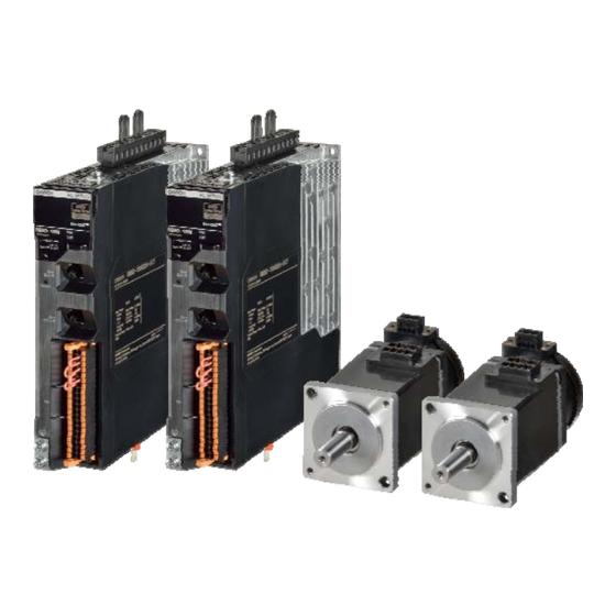
1.2. Servo System constructed in this guide This 1S-series Startup Guide for multi-axis setup and tuning (hereafter referred to as “this Guide”) contains instructions to set-up and tune an X-Y stage system composed of two 1S-series AC Servo Drives. The following figure shows the system configuration and devices that are used in this Guide. The system configuration is shown in the following figure. - Page 13 NJ-series Power Supply Unit NJ-PA3001 EtherCAT communications cables XS5W-T421-CMD-K AC Servo Drives R88D-1SN01L-ECT 1S-series AC Servomotors and Servo Drives User’s Manual (with AC Servo Motors R88M-1M10030S Built-in EtherCAT Power cables R88A-CA1A003S Communications) (Cat. No. I586) Encoder Cables R88A-CR1A003C • Automation software...
-
Page 14: Before You Begin
2. Before You Begin 2.1. Installing the Sysmac Studio The Sysmac Studio is the Support Software that you use for an NJ-series Controller. On it, you can set-up the Controller configurations, parameters, and programs, and you can debug and simulate operation. Install the Sysmac Studio on your computer. -
Page 15: Assembling The Hardware
2.2. Assembling the Hardware This section describes how to assemble the hardware used in the system. This section gives an overview of the assembly procedures. Refer to the manuals for the devices that are used in the system for detailed assembly procedures and safety precautions. Precautions for Safe Use Always turn OFF the power supply to the Controller and to the Servo Drives before you attempt any of the following. -
Page 16: Wiring The Devices
2.3. Wiring the Devices This section describes how to wire the hardware devices. This section gives an overview of the wiring procedures. Refer to the manuals for the devices that are used in the system for detailed wiring procedures and safety precautions. Wiring the Rack Power Supply Unit Wire the Power Supply Unit to the power supply. - Page 17 Laying EtherCAT Communications Cables Connect the EtherCAT slave communications cables between the built-in EtherCAT port on the CPU Unit and the EtherCAT slaves as shown in the following figure. Connect the communications cable from the built-in EtherCAT port to the input port on the first slave, and then connect the communications cable to the next slave to the output port on the first slave.
- Page 18 Wiring the Servo Drives and the Servomotors Wire the Servo Drives and the Servomotors as shown in the following figure.
- Page 19 Wiring the Control Input Signals for the Servo Drives Wire the control input signals for the Servo Drive using the R88A-CN101C Control I/O connector (CN1). For details on wiring, refer to the AC Servomotors/Servo Drives 1S-series with Built-in EtherCAT Communications User's Manual (Cat. No. I586). When using the default Servo parameters, please wire the immediate stop input (ESTOP), negative drive prohibit input (NOT), and the positive drive prohibit input (POT).
-
Page 20: Performing Setup
3. Performing setup 3.1. Two axis servo system operation This section describes the operation of two-axis Servo system that is set up in this Guide. In this system, axis 0 and axis 1 are set up for an XY stage. The mechanical configuration of axis 0 and axis 1 are as shown in the following table. - Page 21 The XY stage will repeatedly travel between two points using linear interpolation with a 2 seconds dwell time after each movement. Interpolation velocity: 250 mm/s Acceleration rate: 8000 mm/s² Deceleration rate: 8000 mm/s² Dwell time: 2 seconds 50 mm 0 mm 50 mm Dwell time: 2 seconds The speed waveforms for axis 0 and axis 1 are shown below...
-
Page 22: System Setup Procedures
Multiple drive Easy tuning for gain adjustment 3.3. Creating project with Auto connection Start the Sysmac Studio: Select All Programs − OMRON − Sysmac Studio − Sysmac Studio from the Windows Start Menu. Create a project in the Sysmac Studio Click the... - Page 23 Sysmac Studio will browse and connect to the controller This concludes the procedure to create a project file with auto connection Additional Information For creating a project offline or specific procedures please refer to the Sysmac Studio Version 1 Operation Manual (Cat. No. W504).
-
Page 24: Creating The Ethercat Network Configuration
3.4 Creating the EtherCAT Network Configuration Two R88D-1SN01L-ECT Servo Drives are registered in the EtherCAT network configuration Double-click EtherCAT under Configurations and Setups in the Multiview Explorer. The EtherCAT page is displayed in the Edit Pane. Right click on the Master and select Compare and Merge with Actual Network Configuration... - Page 25 The Compare and Merge with Actual Network Configuration window is displayed Click on Apply actual network configuration to apply the actual network configuration. Click Apply to confirm: A pop-up message confirmed the network configuration. Click the Close Button Confirm the detected configuration and close the window...
-
Page 26: Creating Motion Axes
Disconnect from the controller 3.5 Creating motion axes This section describes how to add axes used to control Servo Drives. Axes will be created based on detected Servo Drives. Right click on the Master and select Assign Drives to Axes Confirm axes allocation by clicking the Yes Button Confirm the list of Axes added and Click the Ok Button... - Page 27 Right-click Axis Settings in the Multiview Explorer and select Axis setting table. Axis number has been set to 0 and 1, Axis type to Servo axis and Output device 1 to Node: 1 and Node: 2 on CH1 (Channel 1). Project transfer to synchronize Sysmac Studio project and the CPU unit Click the Connect Button on the Toolbar Click the Transfer to Controller Button on the Toolbar...
- Page 28 Click the Yes Button The operating mode changes to PROGRAM mode, and the Sysmac Studio starts transferring the project to the CPU Unit. During the transfer, a progress bar appears in the Synchronize Pane. After download completion, Click The Yes Button to switch to RUN mode. The transfer is completed, Click the Ok Button...
- Page 29 Apply Drive/Motor data to axis via network reading Right-click Axis Settings in the Multiview Explorer and select Apply drive data to axis settings. Click the Yes Button to acquire data from the servo drive via EtherCAT Network Applied axis settings are based on drive and motor data: Command pulse count per motor rotation is set to 8,388,608 following the 23 bits resolution of the motor.
- Page 30 Modification of axis settings to match the XY stage System Disconnect from the Controller Right-click Axis Settings in the Multiview Explorer and select Axis setting table. Edit axis settings according to the XY stage ball screw system Note: Alternatively, Unit conversion settings can also be modified before transferring the project; in that case operation settings will be scaled based on mm units and drive data.
- Page 31 An axes group is added to the Multiview Explorer. The new axes group is displayed as MC_Group000. Right-click the group that you added in the Multiview Explorer and select Edit from the menu. The axes group settings are displayed on the Axes Group Basic Settings Display in the Edit Pane.
-
Page 32: Program Making And Transfer To The Cpu Unit
Program making and transfer to the CPU Unit Create the instructions to perform linear interpolation of two axes. The following instructions are created. To do so, we will use axis variables, an axes group, and motion control instructions. Rung 0: Axes Servo ON Rung 1: Axes homing to zero position preset Rung 2: Axis group enable Rung 3: Absolute position assigned to input variables... - Page 33 Transfer to the CPU Unit Click the Connect Button on the Toolbar Click the Transfer to Controller Button on the Toolbar Click the Execute Button to transfer the project from the computer to the CPU unit Click the Yes Button The operating mode changes to PROGRAM mode, and the Sysmac Studio starts transferring the project to the CPU Unit.
-
Page 34: Drives And Motors Parameters Setup
3.7 Drives and motors parameters setup This section explains the procedure to setup parameters of drives and motors. The absolute encoder must be set up the first time it is used, and when the rotation data is initialized to 0. Right-click the Servo Drive and select Setup and Tuning from the menu. - Page 35 Click the Launch Motor and Encoder view Button. The Encoder Properties Tab Page appears. Click the Clear system Button. An Absolute Value Clear Error (error display number: 2701) will occur, and a dialog box indicating "Restart the drive to complete the operation." Click the Yes Button.
- Page 36 Check the motor rotation direction and modify settings if required 6. Adjust the motor rotation direction and transfer to the drive 7. Validate the motor operation Apply the test run configuration, activate the Servo ON and initiate the movement Note: In case of Error 87.00 ESTP input, please check your wiring connection or disable the error stop input (IN1) as explained in A-1 Settings When Control Input Signals Are Not Wired details on the settings that you must change in this case.
- Page 37 Click the Back to Portal Button Please repeat the same operation for the node 2. Following above procedure, drives have been restarted to apply Input settings. Please Reset the EtherCAT Slave Communication Error in the CPU Unit with Troubleshooting window. Click on Reset All button...
-
Page 38: Easy Tuning (Multiple Drives)
3.8 Easy Tuning (Multiple Drives) In this section we will explain how to perform Easy tuning for multiple Drives simultaneously. The Motion Controller will perform the motion profile. Before running the program, be sure to place the XY system in the homing position required. Confirm operating mode of the CPU Unit is in RUN mode and then use control BOOL variables (set/reset) to control the motion control instructions. - Page 39 Perform the easy tuning (Multiple drives) 1. Right-click Node1: R88D-1SN01L-ECT under Configurations and Setup -EtherCAT in the Multiview Explorer, and select Setup and Tuning from the menu. The Setup and Tuning Portal appears in Edit Pane 2. Click the Easy Tuning Button under Tuning (Multiple Drives) Select Drives to Tune and click the Ok Button...
- Page 40 3. Tuning configuration Select Simple mode and click Next 4. Profile and criteria The motion profile generator is the Motion Controller. Adjust criteria to achieve tuning and click Next button Precautions for Correct Use The Load Characteristic Estimation function may not operate properly under the following conditions.
- Page 41 5. Auto Tune Monitor Click the Start Button Gain will be increased gradually until achieving the specified settling time. The positioning window, specify the position deviation to determine that the positioning is completed. If it detects a vibration above the vibration detection level during tuning, an adjustment failure will occur.
- Page 42 6. Check Behavior Click the Record Button Monitor data will be traced and automatically scaled Confirm the behavior and click the Next Button...
- Page 43 7. Finish Confirm new gain parameters and save to EEPROM Click the Ok Button The easy tuning wizard for multiple drives is completed Click the Finish Button...
-
Page 44: Annex
ANNEX A-1 Settings when control input signals are not wired An error will occur in the CPU Unit if the Servo parameters for the Servo Drive are left at their default values when the Servo Drive control input signals are not wired. This is because the CPU Unit stops operation when a drive prohibit or immediate stop signal is detected. - Page 45 Click the Quick Parameter Setup and I/O Monitor Button. The following dialog box appears. Click the Yes Button. The Motor and Encoder setting Page appears. Click the Next Button The Input Signals setting Page appears.
- Page 46 Change the signal allocation of the below listed input signal, and then click the Transfer to Drive Button. • Error Stop Input • Positive Drive Prohibit Input • Negative Drive Prohibit Input The following dialog box appears. Click the Yes Button The drive restarts and you return to the Input Signals setting Page.
- Page 47 Click the Next Button Please Set Node2: R88D-1SN01L-ECT(E002) in the same way as Node1. Please click to the Copy Settings Button The Copy Settings window appears.
- Page 48 Check boxes and click the Execute button to start the procedure Click the Yes Button to confirm the copy settings Click the Yes Button to transfer settings to target drive The target drive is restarting...
- Page 49 Settings are now effective in the target drive, click the Ok Button Click the Close Button Click the Finish Button This concludes the procedure to change Input settings of Node 1 and Node 2. 10. Following above procedure, drives have been restarted to apply Input settings. Please Reset the EtherCAT Slave Communication Error in the CPU Unit with Troubleshooting window.
- Page 50 Confirm the below message and lick on Yes button Errors are now resetted...
-
Page 51: Program Making With Structured Text
A-2 Program making with structured text Below is an alternative program to move the XY stage with structured text. Power1(Axis:=MC_Axis000, Enable:=ServoLock); Power2(Axis:=MC_Axis001, Enable:=ServoLock); Home1(Axis:=MC_Axis000, Execute:=Home); Home2(Axis:=MC_Axis001, Execute:=Home); Group1(AxesGroup:=MC_Group000, Execute:=GroupEnable); Distance1[0]:=0; Distance1[1]:=0; Distance2[0]:=50; Distance2[1]:=50; Dwell_Time1:=TIME#2s; Dwell_Time2:=TIME#2s; Dwell1(In:=Start AND NOT Complete, PT:=Dwell_Time1, Q=>Go_Linear1); Dwell2(In:=Start AND NOT Complete... - Page 52 Note: Do not use this document to operate the Unit. 2017 I827-E1-01 0317 (0317)
Need help?
Do you have a question about the R88M-1M10030S and is the answer not in the manual?
Questions and answers