Table of Contents
Advertisement
Quick Links
Advertisement
Table of Contents

Related Manuals for AXIOMTEK SBC82400


Summary of Contents for AXIOMTEK SBC82400
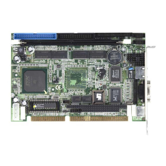
- Page 1 SBC82400 Single Chip Half Size ISA CPU CARD with CRT, Ethernet User’s Manual...
- Page 2 Disclaimers The information in this manual has been carefully checked and is believed to be accurate. AXIOMTEK Co., Ltd. assumes no responsibility for any infringements of patents or other rights of third parties which may result from its use. AXIOMTEK assumes no responsibility for any inaccuracies that may be contained in this document.
- Page 3 Wear a wrist-grounding strap, available from most electronic component stores, when handling boards and components. Trademarks Acknowledgments AXIOMTEK is a trademark of AXIOMTEK Co., Ltd. IBM is a registered trademark of International Business Machines Corporation. MS-DOS, and Windows ’95/98/NT/2000 are trademarks of Microsoft Corporation.
- Page 4 This page does not contain any information.
-
Page 5: Table Of Contents
T a b l e o f C o n t e n t s Chapter 1 Introduction............1 1.1 General Description............1 1.2 Secpifications ..............2 Chapter 2 Jumpers and Connectors........5 2.1 Board Dimensions ............6 2.2 Board Layout..............7 2.3 Jumper Settings.............8 2.3.1 CPU CLK SPEED: JP1, JP2, JP7, JP8 ........9 2.3.2 CPU is HCLK X1 or X2: JP3, JP12 .......... - Page 6 Chapter 3 Hardware Description........24 3.1 Microprocessors............24 3.2 CPU Bus Clock.............24 3.3 BIOS ................24 3.4 System Memory ............24 3.5 I/O Port Address Map ..........25 3.6 Interrupt Controller............26 Chapter 4 Award BIOS Utility ..........28 4.1 BIOS Introduction ............28 4.2 BIOS Setup ..............28 4.2.1 Standard CMOS Setup...............
-
Page 7: Chapter 1 Introduction
Introduction General Description The SBC82400 is the ultimate cost-effective solution of 486-level embedded half card. The SBC82400 comes with an embedded high- performance STPC Consumer-II microprocessor and 32MB SDRAM onboard. For maximum performance, it also has one optional DIMM socket that can support up to 128 MB memory. -
Page 8: Secpifications
SBC82400 ISA Half-Size CPU Board Series User’s Manual Secpifications Onboard STPC Consumer-II microprocessor System Chipset Integrated in Consumer-II Cache memory Integrated L1 8Kbyte write back cache System memory 128MB maximum First bank: onboard 32MB Second bank: one 168-pin DIMM socket supporting... - Page 9 SBC82400 ISA Half-Size CPU Board Series User’s Manual Ethernet Realtek 8100C PCI Bus 10/100M Base-T Power Management Supports Plug & Play, APM(ACPI support) Graphics Graphics function is integrated in Consumer-II Up to 4MB long linear frame buffer Supports CRT connector...
- Page 10 SBC82400 ISA Half-Size CPU Board Series User’s Manual This page does not contain any information. Introduction...
-
Page 11: Chapter 2 Jumpers And Connectors
SBC82400 ISA Half-Size CPU Board Series User’s Manual C h a p t e r 2 Jumpers and Connectors Jumpers and Connectors... -
Page 12: Board Dimensions
SBC82400 ISA Half-Size CPU Board Series User’s Manual Board Dimensions Jumpers and Connectors... -
Page 13: Board Layout
SBC82400 ISA Half-Size CPU Board Series User’s Manual Board Layout Jumpers and Connectors... -
Page 14: Jumper Settings
SBC82400 ISA Half-Size CPU Board Series User’s Manual Jumper Settings The SBC82400 is configured to match the needs of the application with the proper jumper settings. The table below is a summary of all the jumpers and their default settings for the onboard devices. -
Page 15: Cpu Clk Speed: Jp1, Jp2, Jp7, Jp8
SBC82400 ISA Half-Size CPU Board Series User’s Manual 2.3.1 CPU CLK SPEED: JP1, JP2, JP7, JP8 Options Setting JP1, JP2, JP7, JP8 CPU BUS CLK JP1 JP2 JP7 JP8 50 MHz (1-2) (2-3) (2-3) (2-3) 60 MHz (2-3) (1-2) (2-3) (2-3) -
Page 16: Com2 Rs-232/422/485 Selection: Jp9, Jp10, Jp11
SBC82400 ISA Half-Size CPU Board Series User’s Manual 2.3.5 COM2 RS-232/422/485 Selection: JP9, JP10, JP11 COM2 JP10 JP11 RS-232 (default) 3-5, 4-6 3-5, 4-6 RS-422 1-3, 2-4 1-3, 2-4 RS-485 5-6, 7-8 1-3, 2-4 1-3, 2-4 JP10/11 2.3.6 CMOS Clear Jumper: JP13... -
Page 17: Diskonchip Memory Segment Selection: Jp17
2.3.10 Watchdog Trigger Mode Selection: JP18 The watchdog timer is an indispensable feature of the SBC82400. It has a sensitive error detection function and a report function. When the CPU processing comes to a halt, the watchdog either generates a NMI or resets the CPU. -
Page 18: Connectors
SBC82400 ISA Half-Size CPU Board Series User’s Manual Connectors The connectors allow the CPU card to connect with other parts of the system. Ensure that all connectors are in place and firmly attached. The following table lists the function of each connector on the SBC82400. -
Page 19: Flat Panel Bezel Connector: Cn2
SBC82400 ISA Half-Size CPU Board Series User’s Manual 2.4.1 Flat Panel Bezel Connector: CN2 Power LED This connector, designated at Pins 1 and 5 of CN2, connects the system power LED indicator to its respective switch on the case. Pin 1 is assigned as +, and pin 5 is as -. -
Page 20: Mouse & Keyboard Connectors: Cn4, Cn5
SBC82400 ISA Half-Size CPU Board Series User’s Manual 2.4.2 Mouse & Keyboard Connectors: CN4, CN5 The SBC82400 provides a mouse and Keyboard interface via two 5-pin connectors. The pin assignment of these keyboard and mouse connectors is shown below. CN4: Mouse Connector Pin Assignment... -
Page 21: Power Connector: Cn7
SBC82400 ISA Half-Size CPU Board Series User’s Manual 2.4.4 Power Connector: CN7 CN7 is the +5V/+12V power input connector of the SBC82400. Description +12V 2.4.5 ACPI Connector: CN8 Advanced Configuration and Power Interface defines a flexible and extensible interface that allows system designers to select appropriate cost/feature trade-offs for power management. -
Page 22: Compact Flash Connector: Cn9
SBC82400 ISA Half-Size CPU Board Series User’s Manual 2.4.6 Compact Flash Connector: CN9 The SBC82400 is equipped with a CompactFlash socket on the solder side and it supports the CompactFlash through the IDE2 interface. The socket itself is especially designed to prevent any incorrect installation of the CompactFlash card. -
Page 23: Ethernet Connector: Lan1
SBC82400 ISA Half-Size CPU Board Series User’s Manual 2.4.7 Ethernet Connector: LAN1 LAN1: RJ-45 Connector Pin Assignment Signal Tx+ (Data transmission positive Tx- (Data transmission negative) 1 2 3 4 5 6 7 8 Rx+(Data reception positive) RJ45 termination RJ45 termination... -
Page 24: Pc/104 Connectors: J1 And J2
SBC82400 ISA Half-Size CPU Board Series User’s Manual 2.4.8 PC/104 Connectors: J1 and J2 The PC/104 is an industrial standard. It is a compact form factor with dimensions of 3.6” x 3.8” and is fully compatible with the ISA Bus. The PC/104 interface is able to adapt off-the- shelf PC/104 modules, such as sound module, fax modem module, multi-I/O module and etc. - Page 25 SBC82400 ISA Half-Size CPU Board Series User’s Manual J2: PC/104 Bus Pin Assignments Pin# Pin Name Pin# Pin Name Pin# Pin Name Pin# Pin Name MEMCS16* SBHE* IOCS16* LA23 IRQ10 LA22 IRQ11 LA21 IRQ12 LA20 IRQ15 LA19 IRQ14 LA18 DACK0*...
-
Page 26: Parallel Port Interface: Lpt1
SBC82400 ISA Half-Size CPU Board Series User’s Manual 2.4.9 Parallel Port Interface: LPT1 The SBC82400 has a multi-mode parallel port to support: Standard mode IBM PC/XT, PC/AT and PS/2 compatible with bi- directional parallel port Enhanced mode Enhance parallel port (EPP) compatible with EPP 1.7 and EPP 1.9 (IEEE 1284 compliant) -
Page 27: Serial Port Interface: Com1 And Com2
SBC82400 ISA Half-Size CPU Board Series User’s Manual 2.4.10 Serial Port Interface: COM1 and COM2 The SBC82400 has two onboard serial ports: COM1 is RS232 and COM2 is RS-232/422/485, jumper selectable. Both ports feature +5V/+12V power capability on pin 1 and pin 8, depending on the jumper setting 2.4.10.1 RS-232 Connectors... -
Page 28: Irda Connector: Ir1
SBC82400 ISA Half-Size CPU Board Series User’s Manual 2.4.11 IrDA Connector: IR1 IR1 is a 5-pin IrDA connector for wireless communication. N.C. IRRX IRTX 2.4.12 Floppy Disk Controller: FDD1 The SBC82400 provides a 34-pin box-header connector, CN18, for up to two floppy drives support. The floppy drives could be any one of the following types: 5.25"... -
Page 29: Ide Interface Connector: Ide1
SBC82400 ISA Half-Size CPU Board Series User’s Manual 2.4.13 IDE Interface Connector: IDE1 The SBC82400 includes one IDE controller that supports IDE drivers. IDE1: 40-pin IDE Connector Pin Assignment Description Description Description Reset # Data 7 Data 8 Data 6... -
Page 30: Chapter 3 Hardware Description
The Host Clock can be doubled inside the CPU and isintended to operate in the range of 25MHz to 100MHz. BIOS System BIOS used on the SBC82400 is Award Plug and Play BIOS. The SBC82400 contains a single 2Mbit Flash EPROM. System Memory... -
Page 31: I/O Port Address Map
SBC82400 ISA Half-Size CPU Board Series User’s Manual I/O Port Address Map The CPU card communicates via I/O ports. It has a total of 1KB port addresses that can be assigned to other devices via I/O expansion cards. Address Devices... -
Page 32: Interrupt Controller
SBC82400 ISA Half-Size CPU Board Series User’s Manual Interrupt Controller The SBC82400 is a fully PC compatible control board. consists of 16 ISA interrupt request lines and 4 of the 16 can be either ISA or PCI. The mapping list of the 16 interrupt... - Page 33 SBC82400 ISA Half-Size CPU Board Series User’s Manual This page does not contain any information. Hardware Description...
-
Page 34: Chapter 4 Award Bios Utility
C h a p t e r 4 Award BIOS Utility Chapter 4 describes the different settings available in the Award BIOS that comes with the SBC82400. Also, contained here are instructions on how to set up the BIOS configuration. BIOS Introduction... - Page 35 SBC82400 ISA Half-Size CPU Board Series User’s Manual In general, the arrow keys are used to highlight items, <Enter> to select, the <PgUp> and <PgDn> keys to change entries, <F1> for help and <Esc> to quit. Phoenix-AwardBios Setup Utility Standard CMOS Features...
-
Page 36: Standard Cmos Setup
SBC82400 ISA Half-Size CPU Board Series User’s Manual 4.2.1 Standard CMOS Setup “Standard CMOS Setup” is used to record some basic hardware configurations in the computer system and set the system clock and the error handling. If the motherboard is already installed in a working system, there is no need to enter this option. - Page 37 SBC82400 ISA Half-Size CPU Board Series User’s Manual Date The date format is <day>, <date> <month> <year>. Press <F3> to show the calendar. The day of week, from Sun to Sat, determined by the BIOS, is read only The date, from 1 to 31 (or the maximum allowed...
- Page 38 SBC82400 ISA Half-Size CPU Board Series User’s Manual number of CYLS. LANDZONE landing zone cylinders number of number of HEADS SECTORS heads sectors HDD access PRECOMP write precom MODE mode If there is no hard disk drive installed, select NONE and press <Enter>.
- Page 39 SBC82400 ISA Half-Size CPU Board Series User’s Manual Halt On This field determines whether the system will halt if an error is detected during power up. The system boot will halt on any error No errors detected. (default) Whenever the BIOS detects a non-...
-
Page 40: Advanced Bios Features
SBC82400 ISA Half-Size CPU Board Series User’s Manual 4.2.2 Advanced BIOS Features This section is used to configure and improve the system and set up some system features according to the user’s preference. Phoenix – AwardBIOS CMOS Setup Utility Advanced BIOS Features... - Page 41 SBC82400 ISA Half-Size CPU Board Series User’s Manual Virus Warning This item protects the boot sector and partition table of the hard disk against accidental modifications. If an attempt is made, the BIOS will halt the system and display a warning message. If this occurs, the user can either continue the operation or run an anti- virus program to locate and remove the problem.
- Page 42 SBC82400 ISA Half-Size CPU Board Series User’s Manual Boot Up Floppy Seek During POST, BIOS will determine the floppy disk drive type, 40 or 80 tracks. 360Kb type is 40 tracks while 720Kb, 1.2MB and 1.44MB are all 80 tracks. The default value is “Enabled”.
- Page 43 SBC82400 ISA Half-Size CPU Board Series User’s Manual Typematic Rate Setting This determines the typematic rate of the keyboard. The default value is “Disabled”. Enable typematic rate and typematic delay Enabled programming Disable typematic rate and typematic delay programming. The system BIOS will use default value...
- Page 44 SBC82400 ISA Half-Size CPU Board Series User’s Manual Security Option This item limits the access to the system and Setup, or just to Setup. The default value is “Setup”. The system will not boot and access to Setup will be...
-
Page 45: Advanced Chipset Features
SBC82400 ISA Half-Size CPU Board Series User’s Manual 4.2.3 Advanced Chipset Features Since the features in this section are related to the chipset on the CPU board and are completely optimized, changing the default settings in this setup table is not recommended unless the user is well oriented with the chipset features. - Page 46 SBC82400 ISA Half-Size CPU Board Series User’s Manual DRAM Clock The DRAM clock value is set depending on whether the board has paged DRAMs or EDO (extended data output) DRAMs. The available choices are 66 MHz and Host CLK. Memory Hole To improve performance, certain space in memory is reserved for ISA cards.
-
Page 47: Integrated Peripherals
SBC82400 ISA Half-Size CPU Board Series User’s Manual 4.2.4 Integrated Peripherals This option sets the hard disk configuration, mode and port. Phoenix – AwardBIOS CMOS Setup Utility Integrated Peripherals On-Chip Local Bus IDE Enabled IDE Buffer for DOS & Win... - Page 48 SBC82400 ISA Half-Size CPU Board Series User’s Manual ON-Chip Local Bus IDE The Chipset Contains a Local Bus IDE Interface With Support fro Two IDE Channels Select Enabled to Activate The Primary IDE Interface. Select Disable to Deactivate This Interface...
- Page 49 SBC82400 ISA Half-Size CPU Board Series User’s Manual IR Mode To Select the IR Port operation mode IrDA, ASKIR, FIR IR IRQ Select Select the IR Port IRQ level. IRQ3, IRQ4, IRQ10, IRQ11. Onboard Parallel Port This item determines access onboard parallel port controller with which I/O address.
-
Page 50: Power Management Setup
SBC82400 ISA Half-Size CPU Board Series User’s Manual 4.2.5 Power Management Setup The Power Management Setup is to save energy of the system effectively. It will shut down the hard disk and turn OFF video display after a period of inactivity. - Page 51 SBC82400 ISA Half-Size CPU Board Series User’s Manual Power Management This item is to select the Power Management mode. The choice: Standby Mode, HDD Power Down PM Control by APM When enabled, an Advanced Power Management device will be activated to enhance the Max. Power Saving mode and stop the CPU internal clock.
-
Page 52: Pnp/Pci Configuration
SBC82400 ISA Half-Size CPU Board Series User’s Manual 4.2.6 PNP/PCI Configuration This section describes the PCI bus system configuration. PCI or Personal Computer Interconnect is a system which allows I/O devices to operate at speeds nearing the speed of the CPU when communicating with its own special components. - Page 53 SBC82400 ISA Half-Size CPU Board Series User’s Manual Resource controlled by The Award Plug and Play BIOS has the capacity to automatically configure all of the boot and the Plug and Play compatible devices. However, this capability means absolutely nothing unless using a Plug and Play operating system such as Windows98.
-
Page 54: Set Password
SBC82400 ISA Half-Size CPU Board Series User’s Manual 4.2.7 Set Password ENTER PASSWORD: Type the password with eight characters at most, and press <Enter>. The password typed will now clear any previously entered password from CMOS memory. Then, confirm the password by typing the password again and pressing <Enter>. -
Page 55: Save & Exit Setup
SBC82400 ISA Half-Size CPU Board Series User’s Manual 4.2.8 Save & Exit Setup This is to determine whether or not to accept the modifications. Typing “Y” quits the setup utility and saves all changes into the CMOS memory. Typing “N” brigs back to Setup utility. -
Page 56: Appendix A Watchdog Timer
The SBC82400 CPU card uses version 2.0 of the watchdog timer. This onboard WDT generates either a system reset or non-maskable interrupt (NMI), depending on the settings made on jumper JP18 of SBC82400. Follow the steps below to enable and program the watchdog function of SBC82400. Start ↓... - Page 57 SBC82400 ISA Half-Size CPU Board Series User’s Manual 0.5 sec. 5 secs. 50 secs. 100 secs. 1 sec. 10 secs. 100 secs. 200 secs. 1.5 secs. 15 secs. 150 secs. 300 secs. 2 secs. 20 secs. 200 secs. 400 secs.
Need help?
Do you have a question about the SBC82400 and is the answer not in the manual?
Questions and answers