
Subscribe to Our Youtube Channel
Related Manuals for Beckman Coulter JCF-Z


Summary of Contents for Beckman Coulter JCF-Z
- Page 1 Instructions For Use JCF-Z Zonal and Continuous Flow Rotor PN JCFZ-IM-12AB June 2019 Beckman Coulter, Inc. 250 S. Kraemer Blvd. Brea, CA 92821 U.S.A.
- Page 2 PN JCFZ-IM-12AB (June 2019) © 2019 Beckman Coulter, Inc. All rights reserved. Beckman Coulter, the stylized logo, and the Beckman Coulter product and service marks mentioned herein are trademarks or registered trademarks of Beckman Coulter, Inc. in the United States and other countries.
-
Page 3: Revision History
Revision History This document applies to the latest software listed and higher versions. When a subsequent software version changes the information in this document, a new issue will be released. Initial Issue, 02/08 Issue AA, 03/14 Updates were made to the document format. Changes were made to Specifications, Installing the Zonal Interlock Accessory, Run Procedure For Pelleting Sample (Continuous Flow Cores), Standard Zonal Core, and Zonal Bracket Kit Contents. - Page 4 Revision History PN JCFZ-IM-12AB...
-
Page 5: Safety Notice
This rotor was developed, manufactured, and tested for safety and reliability as part of a Beckman Coulter centrifuge/rotor system. Its safety or reliability cannot be assured if used in a centrifuge not of Beckman Coulter’s manufacture or in a Beckman Coulter centrifuge that has been modified... - Page 6 Safety Notice Alerts for Danger, Warning, Caution, Important, and Note Handle body fluids with care because they can transmit disease. No known test offers complete assurance that such fluids are free of micro-organisms. Some of the most virulent—Hepatitis (B and C)) viruses, HIV (I–V, atypical mycobacteria, and certain systemic fungi—further emphasize the need for aerosol protection.
- Page 7 Alerts for Danger, Warning, Caution, Important, and Note WARNING The processing of large volumes of pathogenic materials in the JCF-Z rotors can produce extremely potent concentrations. Agents that are relatively harmless in their naturally occurring dilute state may become infectious when concentrated.
- Page 8 Safety Notice Alerts for Danger, Warning, Caution, Important, and Note viii PN JCFZ-IM-12AB...
-
Page 9: Table Of Contents
Contents Revision History, iii Safety Notice, v Alerts for Danger, Warning, Caution, Important, and Note, v CHAPTER 1: The Process of Continuous Flow and Zonal Centrifugation, 1-1 Continuous Flow Centrifugation, 1-1 ZONAL CENTRIFUGATION, 1-3 CHAPTER 2: Description, 2-1 Rotor Components, 2-1 Specifications, 2-6 CHAPTER 3: Assembly and... - Page 10 Contents Step 9, 3-15 Step 9a, 3-15 Step 9b, 3-16 Step 10, 3-17 Step 11, 3-18 Step 12, 3-18 Step 13, 3-19 CHAPTER 4: Preparing for Operation, 4-1 Determining the Rotor Speed, 4-1 Determining The Flow Rate: Large And Standard Pellet Cores, 4-2 Setting The Temperature, 4-5...
- Page 11 Sizes 14 and 15 Tubing, B-4 Step 4. Attach the Tubing to the Zonal Bracket, B-5 Step 5. Attach Tubing to the JCF-Z Seal Assembly Housing, B-6 Step 6. Attach a Scavenger Line (Optional), B-7 JCF-Z Rotor Warranty And Seal Assembly Warranty...
- Page 12 Illustrations Illustrations Cross Section of a Continuous Flow Rotor, 1-2 Cross Section of Zonal Rotor with Standard Zonal Core, 1-3 Rotor Components., 2-2 Seal and Transfer Assemblies, 2-3 Identifying O-Rings. O-rings requiring occasional replacement are shown, actual size., 2-5 Tools Provided in Tool Kit 335143., 3-2 Speed and Flow Rate Nomogram, Standard Pellet Core., 4-4...
- Page 13 Pushing Down on Seal/Bearing Assembly to Tension Spring, A-7 A.11 Finishing Rotor Assembly, A-7 Avanti J Series Centrifuge Chamber with JCF-Z Rotor and Zonal Bracket Installed, B-1 Attaching the Bracket to the Chamber Wall, B-3 Inserting Size 16 Tubing through the...
- Page 14 Tables Tables JCF-Z Continuous Flow Applications, 1-2 JCF-Z Zonal Applications, 1-4 Specifications, 2-6 Different Core Specifications, 2-7 J2 and J6 Series Centrifuge Temperature Settings. All settings approximate., 4-6 Two Techniques for Forming an Air Block During Density Gradient Operation, 5-7...
- Page 15 The Process of Continuous Flow and Zonal Centrifugation The JCF-Z rotor, which can be used in Beckman Coulter J2, J6, and Avanti J series centrifuges, has interchangeable cores that enable it to perform both continuous flow and zonal centrifugation. This section describes these processes and their applications.
-
Page 16: The Process Of Continuous Flow And Zonal Centrifugation
Banding in a gradient is appropriate when it is necessary to separate a certain particle from contaminants of different sedimentation velocities in the solution. Table 1.1 JCF-Z Continuous Flow Applications Core Type Typical Sample Type... -
Page 17: Zonal Centrifugation
In the JCF-Z rotor, the zonal technique is useful in separating large particles, such as mammalian viruses and subcellular organelles, from plant or animal tissue homogenates (see Table 1.2). -
Page 18: Jcf-Z Zonal Applications
The Process of Continuous Flow and Zonal Centrifugation ZONAL CENTRIFUGATION Two zonal cores are available with the JCF-Z: standard and reorienting gradient (also known as reograd). These cores are divided into sector-shaped compartments by vanes attached to the core; the rotor is enclosed by a threaded lid. A rotating seal assembly allows fluid to be pumped in and out of the standard zonal core cavity (for loading and unloading only) while the rotor is spinning. -
Page 19: Description
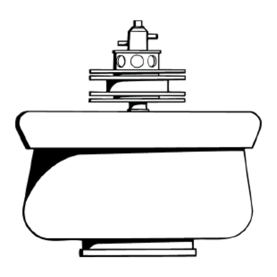
Depending on which core is used, the fully loaded JCF-Z rotor weighs 12 to 14 kg (26 to 31 lb). The seal assembly (except bearings and rotating seal) is warranted for 1 year; other rotor components are warranted for 7 years. - Page 20 Figure 2.1 Rotor Components. The seal and transfer assemblies are described in Figure 2.2. Letters indicate O-rings made 1. Seal Assembly 3. Lid (336282) 7. Standard Zonal Core 10. (354005) of Buna N or of Viton. (Standard 335142; high flow (335141) 4.
-
Page 21: Rotor Components
Description Rotor Components Figure 2.2 Seal and Transfer Assemblies PN JCFZ-IM-12AB... - Page 22 Description Rotor Components 1. Standard Flow (SF) Seal Housing 19. Spring (870654)) 2. Feed Fitting (Standard Flow) (335146) 20. Retaining Ring (870689) 3. Feed Fitting O-ring (824464) 21. Flat Washer (853391) 22. Retaining Seal Mount (336284) 4. Manifold 23. Fitting Retaining Clamp (344108) 5.
-
Page 23: Identifying O-Rings. O-Rings Requiring Occasional Replacement Are Shown, Actual Size
Description Rotor Components Figure 2.3 Identifying O-Rings. O-rings requiring occasional replacement are shown, actual size. 1. Edge of Rotor Bowl (seals lid) (870688) 6. Rotating Seal (824412) 2. Bottom of Rotor Bowl (854519 or 870528 [Viton]) 7. Rotor Lid Stem (815473) 3. -
Page 24: Specifications
Description Specifications Specifications Only values with tolerances or limits are guaranteed data. Values without tolerances are informative data, without guarantee. Table 2.1 Specifications 20 000 rpm Maximum rated speed 2 000 rpm Minimum speed NOTE Necessary for adequate vertical positioning of the rotor contents, except when the reograd core is used. -
Page 25: Different Core Specifications
Description Specifications Table 2.2 Different Core Specifications Rotor Core Max RCF Rotor Pellet k Factors Type Type (x g)* Capacity Capacity (outermost r (mm) (mm) at r (mL) (mL) at 20 000 rpm) Cont. large top: 56 39 900 1250 Flow pellet bottom: 51... - Page 26 Description Specifications PN JCFZ-IM-12AB...
-
Page 27: Assembly And Installation
Installing the Zonal Bracket (Avanti J Series Centrifuges Only) When the JCF-Z rotor is used in any of the Avanti J series centrifuges, a zonal bracket must be installed. See APPENDIX B, Using the JCF-Z Continuous Flow/Zonal Rotor Bracket (Avanti J Series Centrifuges Only) for complete information. -
Page 28: Supplies Required But Not Provided
Assembly and Installation Tools and Supplies Figure 3.1 Tools Provided in Tool Kit 335143. 1. Rotor vise (335127) 4. Small spanner wrench (870666) 2. Plug (335149) and O-ring (812715) 5. 3/16-in. T-bar hex wrench (001311) 3. Large spanner wrench (870667) 6. -
Page 29: Assembling The Rotor
Assembly and Installation Assembling the Rotor Assembling the Rotor Step 1 Assembly is much the same for continuous flow and zonal rotor configurations; assembly steps for both configurations are covered in steps 1 through 13 below. Some steps are for particular cores only and are so identified. -
Page 30: Step 1B
Assembly and Installation Assembling the Rotor Step 1b Install and align the canoe-shaped pellet containers. Small pellet only— NOTE During the run, the small pellet containers may rotate slightly. This rotation can often be prevented by applying a small patch or two of silicone vacuum grease (335148) to the outside of the container before installing it in the core. -
Page 31: Step 1D
Assembly and Installation Assembling the Rotor Step 1d Fit the core and base together, aligning the pin in the core with the hole Reorienting Gradient only— in the base. PN JCFZ-IM-12AB... -
Page 32: Step 2
Assembly and Installation Assembling the Rotor Step 2 Coat both of the bowl O-rings with silicone vacuum grease and install them in the rotor as shown: one in the bottom of the rotor and one around the upper edge. Set the rotor into the rotor vise (which has been bolted to a sturdy surface). - Page 33 Assembly and Installation Assembling the Rotor Step 3 Install the core in the rotor bowl. Note that the “up” side of each core has a small hole in the center. The “down” side has a large hole in the center with a metal drive pin in or across it. PN JCFZ-IM-12AB...
-
Page 34: Step 4
Assembly and Installation Assembling the Rotor Step 4 Screw the lid onto the rotor and tighten it with the large spanner wrench. Align index marks on the lid and rotor (the lid may be tightened past the bowl mark). 1. Large Spanner Wrench (870667) 2. -
Page 35: Step 5
Assembly and Installation Assembling the Rotor Step 5 Coat the O-rings on the transfer tube or transfer tube assembly (reograd core) with silicone vacuum grease. Check the Tygon tubing on the transfer tube to be sure it is clean. Replace this tubing as necessary. -
Page 36: Step 6
Assembly and Installation Assembling the Rotor Step 6 Step 6a 1. Spanner Wrench (870666) 7. Bearing Screw (804063) 2. Seal Mount (336284) 8. 3/16-in. T-bar Hex Wrench (001311) 3. Bearing Assembly 9. Bearing (366190) 4. O-ring (815473) 10. Spring Washer (870658) 5. - Page 37 Assembly and Installation Assembling the Rotor Screw the seal mount into place counterclockwise (it has a left-hand thread) and tighten it with a spanner wrench (870666). Tighten the bearing screw using T-bar hex wrench (001311). CAUTION To avoid damaging the bearings, never press on the bearing assembly with your hand when tightening the bearing screw.
-
Page 38: Step 6B
Assembly and Installation Assembling the Rotor Step 6b Reograd zonal rotor Coat the rotor lid stem O-ring with silicone vacuum grease and slip it onto the rotor lid shaft. Apply Spinkote lubricant to the threads of the shaft. Insert the transfer tube into the shaft and turn it counterclockwise onto the lid until it is firmly seated. -
Page 39: Step 7
Assembly and Installation Assembling the Rotor Step 7 Standard zonal and continuous flow rotors. Before rotor assembly can be completed, the proper seal housing assembly should be selected and prepared. Your choice depends on the required flow rate: maximum rate for the standard assembly is 45 liters/hour, and for the high flow, 100 liters/hour. -
Page 40: High Flow Seal Housing
Assembly and Installation Assembling the Rotor High Flow Seal Housing Continuous Flow Standpipe must be hooked up to a vacuum to keep bearings dry. 1. Standpipe Step 8 Standard zonal and continuous flow rotors Check the rotating seal to be sure it is not damaged; the sealing surface should be smooth and shiny. Lubricate O-ring (824412) with silicone vacuum grease and put it around the rotating seal. -
Page 41: Step 9
Assembly and Installation Assembling the Rotor Step 9 Step 9a Standard zonal and continuous flow rotors If the seal assembly is already assembled and aligned, assemble the rotor as shown here. Be sure that all O-rings, as well as the threads and center shaft of the lid, are lightly coated with silicone vacuum grease. -
Page 42: Step 9B
Assembly and Installation Assembling the Rotor Step 9b Reograd zonal rotor Install the assembled rotor on the centrifuge drive hub. CAUTION The centrifuge drive hub can be bent if the rotor is dropped onto it or forced sideways. Install the rotor by centering it over the hub and carefully lowering it straight down. -
Page 43: Step 10
Assembly and Installation Assembling the Rotor Step 10 Load the rotor with gradient and sample according to the appropriate procedure in CHAPTER 5, Operation. Then unscrew the transfer tube assembly from the rotor and replace it with the zonal seal cap. 1. -
Page 44: Step 11
Avanti J Series A zonal bracket is needed to support the tubing lines in Avanti J series centrifuges. Refer to APPENDIX B, Using the JCF-Z Continuous Flow/Zonal Rotor Bracket (Avanti J Series Centrifuges Only) complete installation instructions. J2 and J6 Series Centrifuges Thread 1/8-in. -
Page 45: Step 13
Use the #1, one-hole rubber stoppers provided to hold the tubing in the ports as shown. Connectors for 3/16-in. tubing (for a tight fit) are needed on the lines as shown. 1. This port not needed for JCF-Z use. 3. Scavenger line (for continuous flow rotors only) 2. - Page 46 Assembly and Installation Assembling the Rotor 3-20 PN JCFZ-IM-12AB...
-
Page 47: Chapter 4: Preparing For Operation
Determining the Rotor Speed The maximum allowable run speed for the JCF-Z rotor is 20 000 rpm, as long as the mean liquid density in the rotor is 1.45 g/mL or less. If the mean solution density in the rotor is greater than 1.45... -
Page 48: Determining The Flow Rate: Large And Standard Pellet Cores
Preparing for Operation Determining The Flow Rate: Large And Standard Pellet Cores Determining The Flow Rate: Large And Standard Pellet Cores The equations below may be used to determine approximate flow rate F or rotor speed in RPM for specific samples. Figure 4.1 has been generated from equation (3a) for the standard pellet core. - Page 49 Preparing for Operation Determining The Flow Rate: Large And Standard Pellet Cores Before you use the nomogram or equation (3), however, s must be calculated from the known sedimentation coefficient or the known diameter of the particle of interest. If the diameter (D) is known, use equation (4): Equation (4) ρ...
- Page 50 Preparing for Operation Determining The Flow Rate: Large And Standard Pellet Cores Figure 4.1 Speed and Flow Rate Nomogram, Standard Pellet Core. Connect two known scale values with a straight-edge. Read the desired information where it intersects with the third scale. Values vary with viscosity and density: use equation (4) or (5) to determine sr before using this figure to estimate flow rate with the standard core.
-
Page 51: Setting The Temperature
Gradient material should also be precooled if the sample is temperature sensitive. Temperature control will also depend on ambient conditions when the JCF-Z is run above 18 000 rpm. The lowest temperatures which the rotor can be controlled are about 5°C at 19 000 rpm and 15°C at 20 000 rpm. -
Page 52: Analog J2 And J6 Series Centrifuges (Models J2-Hs, J2-21, J2-Hc, J6-Hc, And J-6B)
Preparing for Operation Determining The Liquid Pressure When the entry is correct, press ENTER/RECALL NOTE To clear a COMP ADJ entry, press COMP ADJ , and ENTER/RECALL Table 4.1 J2 and J6 Series Centrifuge Temperature Settings. All settings are approximate. Speed Required Rotor Temperature (°C) (rpm) -
Page 53: Radius Versus Volume For Standard Pellet Core, Standard Zonal
Preparing for Operation Determining Appropriate Gradients measuring the liquid volume it takes to displace the sample out of the rotor. The illustration relates each recovered fraction to its radial position in the rotor. For example, with the standard zonal core, if the desired band begins to emerge when 1000 mL of heavy displacement liquid has been pumped into the rotor, then the inner edge of the band is at a radius of 67.5 mm. - Page 54 Preparing for Operation Determining Appropriate Gradients PN JCFZ-IM-12AB...
-
Page 55: Chapter 5: Operation
Operating Precautions WARNING The processing of large volumes of pathogenic materials in the JCF-Z rotors can produce extremely potent concentrations. Agents that are relatively harmless in their naturally occurring dilute state may become infectious when concentrated. -
Page 56: Continuous Flow Operation
Continuous Flow Operation Pelleting Technique Although the JCF-Z can also perform separations in a gradient or cushion, the rotor is most commonly used for pelleting. Below is a description of pelleting technique which can be used for each of the three continuous flow cores. This technique is illustrated in Figure 5.1. -
Page 57: Run Procedure For Pelleting Sample (Continuous Flow Cores)
Operation Continuous Flow Operation Run Procedure For Pelleting Sample (Continuous Flow Cores) Calibrate the pump flow rate in the range to be used for separation. CAUTION If you use your pump for more than one application, always disconnect and rinse the line in the pump and check that you have set the correct flow rate before installing and using the pump. -
Page 58: Line Connections, Continuous Flow Cores. Using This Tubing
Operation Continuous Flow Operation Figure 5.3 Line Connections, Continuous Flow Cores. Using this tubing arrangement for basic pelleting against the rotor wall. • To fill rotor, clamp C • To load sample, clamp B 1. Lower Fitting 4. Sample 2. Upper Fitting 5. -
Page 59: Purging Air From The System (Continuous Flow Rotor Only)
Operation Purging Air From The System (Continuous Flow Rotor Only) If gauge pressure exceeds 25 psi (175 kPa) during acceleration or rises gradually during centrifugation, you have at least a partial air block. To remove the block: a. Start decelerating the rotor to 2000 rpm. b. -
Page 60: Density Gradient Operation (Continuous Flow Cores)
• Don’t Density Gradient Operation (Continuous Flow Cores) Gradient Or Cushion Separation Techniques The JCF-Z can separate particles in a gradient or cushion. These techniques are described in Table 5.1 and technique B is illustrated in Figure 5.4. -
Page 61: Forming An Air Block
Operation Density Gradient Operation (Continuous Flow Cores) Forming an Air Block During unloading, the rotor contents are displaced toward the center by a very dense liquid pumped to the rotor wall. An air block is needed to cause the displacing solution to enter at the periphery instead of at the top of the gradient. -
Page 62: Gradient Or Cushion Separation Technique, Continuous Flow
Operation Density Gradient Operation (Continuous Flow Cores) Figure 5.4 Gradient or Cushion Separation Technique, Continuous Flow Cores. Technique B, described in Table 5.1, is shown. PN JCFZ-IM-12AB... -
Page 63: Run Procedure For Separating In A Gradient Or Cushion (Continuous Flow Cores)
Figure 5.5 Sucrose Gradient after One Hour, Monitored by Refractometer. Diffusion between the discontinuous layers of the step gradient results in a near-linear gradient. Zonal Operating Techniques And Run Procedures Zonal operation of the JCF-Z is described below and illustrated in Figures Figure 5.7 Figure 5.8. -
Page 64: Line Connections, Standard Zonal Core
Pump the overlay in at 15 to 25 ‡ mL/min. * If you have not already installed a zonal key safety interlock, contact Beckman Coulter to order one. Publication J-TB-025 accompanying the interlock provides complete installation instructions. † Use an auxiliary timer to time centrifugation runs. -
Page 65: Operating Procedure, Standard Zonal Core
Operation Zonal Operating Techniques And Run Procedures Figure 5.7 Operating Procedure, Standard Zonal Core Stop the pump and clamp the lines. 5-11 PN JCFZ-IM-12AB... -
Page 66: Removing And Reinserting Fittings And Liquid Lines
Operation Zonal Operating Techniques And Run Procedures Rotate the fitting retaining clamp as described in Figure 5.8 and remove the fittings and liquid lines from the chamber. Reinstall stoppers in all portholes. Reset the centrifuge controls as necessary. Figure 5.8 Removing and Reinserting Fittings and Liquid Lines 1. -
Page 67: Reorienting Gradient (Reograd) Zonal Core
Operation Zonal Operating Techniques And Run Procedures Reorienting Gradient (Reograd) Zonal Core Calibrate the pump flow rate in the range of 15 to 50 mL/min. Assemble the rotor according to CHAPTER 3, Assembly and Installation. Then refrigerate or warm the rotor and solutions as appropriate prior to use. The rotor may be filled either in the centrifuge or in a cold room. -
Page 68: Ending The Run
Operation Ending The Run Ending The Run Continuous Flow Core Containing Pellet Push the button on the centrifuge control panel. STOP Turn the pump flow rate down. CAUTION Do not turn off the pump completely until the rotor has stopped. Without some flow through the spinning rotor, the bearing housing may overheat and shorten the life of the bearings. -
Page 69: Operating Procedure, Reograd Zonal Core
Operation Ending The Run Figure 5.10 Operating Procedure, Reograd Zonal Core When the rotor has stopped, turn off the pump. Flush the tubing lines (see Flushing The Tubing Lines, later in this section). Clamp the lines. Remove the rotor from the centrifuge and set it in the vise. Remove the rotating seal assembly. -
Page 70: Lowering Rotor Onto Plug. Rotor Contents Will Spill Out
Operation Ending The Run Take the rotor off the vise. Put the plug on the vise. (If the plug is not in the vise, the rotor contents will leak as soon as you take the core out.) Lower the rotor onto the plug (see Figure 5.11). -
Page 71: Disassembling The Rotor. Disassemble As Shown To Remove
Operation Ending The Run Siphon out the liquid. Take the core out of the rotor. Scrape the pellet from the core and bowl (small pellet, see Figure 5.13). Don’t use metal tools to lift the pellet container or to scrape out the pellet, as they can scratch the rotor. -
Page 72: Continuous Flow Core Containing Gradient Or Cushion
Operation Ending The Run Figure 5.13 Removing Small Pellet. Lift out canoe-shaped pellet container and scrape out pellet. 1. Toothpick Finish disassembling the rotor (see Figure 5.12). CHAPTER 6, Care and Maintenance for cleaning instructions. Continuous Flow Core Containing Gradient or Cushion When the auxiliary timer indicates that the run is over, turn the pump off and clamp the sample inlet line. -
Page 73: Standard Zonal Core
Operation Ending The Run While the rotor is spinning at 2000 rpm, pump dense displacement solution at 30 mL/min into the rotor. This first forces the air from the dry tubing into the rotor, creating an air block as shown in Figure 5.1. -
Page 74: Reograd Zonal Core
Operation Ending The Run After the seal housing comes to a stop, install and rotate the plastic fitting retainer so that fittings and liquid lines can be reattached. CAUTION Make sure there is no air in the displacement liquid line. Attach the liquid-filled line and fitting into the lower fitting hole and the collection line into the upper fitting hole. -
Page 75: Flushing The Tubing Lines
Operation Ending The Run Flushing The Tubing Lines After every run, flush the tygon tubing lines according to the following procedure. The rotor can then be disassembled and the components can be cleaned and sterilized according to the procedures in CHAPTER 6, Care and Maintenance. - Page 76 Operation Ending The Run 5-22 PN JCFZ-IM-12AB...
-
Page 77: Chapter 6: Care And Maintenance
• Periodically (at least monthly) inspect the rotor for rough spots or pitting, white powder deposits (frequently aluminum oxide), or heavy discoloration. If any of these signs are evident, do not run the rotor. Contact your Beckman Coulter representative for information about the Field Rotor Inspection Program and the rotor repair center. -
Page 78: Decontamination
If the rotor (and/or accessories) becomes contaminated with radioactive material, decontaminate it using a solution that will not damage the anodized surfaces. Beckman Coulter has tested a number of solutions and found two that do not harm anodized aluminum: RadCon Surface Spray or IsoClean †... -
Page 79: Sterilization And Disinfection
• On the first few uses of a new JCF-Z rotor, or in an older JCF-Z rotor with newly replaced bearings run the rotor from 0 to 5000 rpm and back to 0 rpm three times. This procedure will distribute lubricant around the bearings in the rotating seal assembly, reducing drag. -
Page 80: Smoothing (Lapping) The Rotating Seal
Before returning a rotor or accessory for any reason, prior permission (a Returned Goods Authorization form) must be obtained from Beckman Coulter, Inc. The RGA form may be obtained from your local Beckman Coulter sales office. It should contain the following information: •... -
Page 81: Supply List
2.2, and Figure 2.3. Refer to these Figures for easy identification. Refer to APPENDIX B, Using the JCF-Z Continuous Flow/Zonal Rotor Bracket (Avanti J Series Centrifuges Only) for parts required for the zonal bracket. Table 6.1 Supply List Bearing housing (anodized aluminum) - Page 82 Care and Maintenance Supply List Table 6.1 Supply List Sample transfer tube, standard flow seal assembly 335120 (stainless steel) Sample transfer tube, high flow seal assembly (stainless steel) 335132 Scavenger drain tube (stainless steel) 336286 Screw, manifold (stainless steel) 870690 Seal assembly, high flow 335133 Seal assembly kit, high flow (for continuous-flow operation)
-
Page 83: Troubleshooting
CHAPTER 7 Troubleshooting This section lists possible malfunctions, together with probable causes and corrective actions required. If a problem persists, contact Beckman Coulter (1-800-742-2345 in the United States; customers outside the U.S. should contact their local Beckman Coulter office). Leakage... -
Page 84: Vibration
Troubleshooting Vibration Vibration Rotor vibration can be caused by defective or misaligned bearings (see CHAPTER 3, Step 6a bearing alignment instructions) or by an improperly assembled rotor. Review assembly steps 1 through 13 in CHAPTER 3, Assembling the Rotor, if necessary. PN JCFZ-IM-12AB... -
Page 85: Appendix A: Assembling The Rotating Seal
At properly tensioned spring pressures, the rotating seal is capable of up to two liters per minute of sample throughput in the JCF-Z. Figure A.1 illustrates the components of the transfer tube assembly: the transfer tube (335120, standard flow;... - Page 86 Assembling the Rotating Seal Assembling the Rotating Seal Figure A.2 O-ring (870656) and Silicone Vacuum Grease (335148) PN JCFZ-IM-12AB...
-
Page 87: Fully Assembled Transfer Tube
Assembling the Rotating Seal Assembling the Rotating Seal After lubricating the O-ring, assemble the transfer tube assembly for use in the rotor as shown Figure A.3. Figure A.3 Fully Assembled Transfer Tube Assembly The transfer tube and rotating seal are shown in Figure A.4. -
Page 88: Correct Position Of The Rotating
Assembling the Rotating Seal Assembling the Rotating Seal The beveled end of the transfer tube should protrude out of the seal housing as shown in Figure A.5. Figure A.5 Transfer Tube Beveled End Place the rotating seal on the transfer tube assembly as shown in Figure A.6. -
Page 89: Incorrect Position Of The Rotating Seal (Wrong Spring Tension
Assembling the Rotating Seal Assembling the Rotating Seal If the rotating seal remains in the seal housing (Figure A.7), it is not properly tensioned. (This condition has been virtually eliminated by the new design transfer tube assembly which has a pre-tensioned spring.) Repeat steps 1 through 6 to ensure that the seal is pushed out of the seal housing when spring tension is released (see Figure... -
Page 90: Stationary Seal Housing Mated To Bearing Housing
Assembling the Rotating Seal Assembling the Rotating Seal Assemble the stationary seal housing together with the bearing housing and check to see that the entire seal/bearing housing assembly sits on the rotating seal and rides up on the bearings. This happens because the transfer tube spring supports the weight of the seal/bearing housing when it is properly tensioned (Figure A.9). - Page 91 Assembling the Rotating Seal Assembling the Rotating Seal Push down on the seal/bearing assembly until the transfer tube spring bottoms out (Figure A.10). Figure A.10 Pushing Down on Seal/Bearing Assembly to Tension Spring While continuing to bear down on the seal/bearing housing, tighten the seal/bearing assembly using the T-handle wrench supplied with the rotor (001311).
- Page 92 Assembling the Rotating Seal Assembling the Rotating Seal PN JCFZ-IM-12AB...
-
Page 93: Using The Jcf-Z Continuous Flow/Zonal Rotor Bracket (Avanti J Series Centrifuges Only
Only) Description The zonal bracket is designed for use in Avanti J series centrifuges when the JCF-Z Continuous Flow/ Zonal Rotor is used. The bracket provides support for the inlet and outlet tubing lines, keeping them stable and out of the way of the spinning rotor during high-speed operation. The complete... -
Page 94: Zonal Bracket Kit Contents
Using the JCF-Z Continuous Flow/Zonal Rotor Bracket (Avanti J Series Centrifuges Only) Description Zonal Bracket Kit Contents Two zonal bracket kits are available for use with standard Cole-Parmer size 16 tubing (6.4-mm, 1/4-in. O.D.). Kit (363843) is used with Avanti JXN-30, J-30I, and J-25 series centrifuges; kit (366431) is used with Avanti JXN-26, J-26S XP, J-26 XP, and J-20 series centrifuges. -
Page 95: Assembly Instructions
Using the JCF-Z Continuous Flow/Zonal Rotor Bracket (Avanti J Series Centrifuges Only) Assembly Instructions Assembly Instructions Step 1. Install the Rotor Install the assembled JCF-Z rotor into the Avanti J chamber. See CHAPTER 3, Assembly and Installation, for instructions. Step 2. Attach the Zonal Bracket to the Centrifuge Chamber Wall... -
Page 96: Sizes 14 And
Using the JCF-Z Continuous Flow/Zonal Rotor Bracket (Avanti J Series Centrifuges Only) Assembly Instructions To make it easier to insert the tubing, first carefully cut the end at an angle with scissors or a sharp blade. Insert a piece of tubing through one of the tubing holes, from... -
Page 97: Step 4. Attach The Tubing To The Zonal Bracket
Sizes 16 and 14 tubing: insert a standard-flow feed fitting into each tubing end, as shown in Figure B.5. (For the larger size 15 tubing, which is used with the JCF-Z high-flow seal assembly, feed fittings are not used; see Figure B.7.) -
Page 98: Step 5. Attach Tubing To The Jcf-Z Seal Assembly Housing
Sizes 16 and 14 tubing: the seal housing. press one tubing end over each fitting. Size 15 tubing is used with the JCF-Z high- Size 15 tubing: flow seal assembly, in which the fittings are welded to the housing (Figure B.7). -
Page 99: Step 6. Attach A Scavenger Line (Optional
Figure B.6) down securely. You are now ready to complete setting up the JCF-Z flow system as described in this manual. To attach a scavenger line (optional), follow the instructions in step 6 below. Step 6. Attach a Scavenger Line (Optional) -
Page 100: Attaching A Scavenger
Using the JCF-Z Continuous Flow/Zonal Rotor Bracket (Avanti J Series Centrifuges Only) Assembly Instructions Figure B.8 Attaching a Scavenger Line 1. Scavenger Line 2. Scavenger Port Attach the tubing to the scavenger port. Gently pull the tubing back through the porthole until there is no excess tubing inside the centrifuge. -
Page 101: Jcf-Z Rotor Warranty And Seal Assembly Warranty
Subject to the conditions specified below and the warranty clause of the Beckman Coulter terms and conditions of sale in effect at the time of sale, Beckman Coulter agrees to correct either by repair, or, at its election, by replacement any defects of material or workmanship which develop within seven (7) years after... - Page 102 JCF-Z Rotor Warranty And Seal Assembly Warranty Warranty-2 PN JCFZ-IM-12AB...
- Page 104 © 2019 Beckman Coulter, Inc. All Rights Reserved...
Need help?
Do you have a question about the JCF-Z and is the answer not in the manual?
Questions and answers