Table of Contents
Advertisement
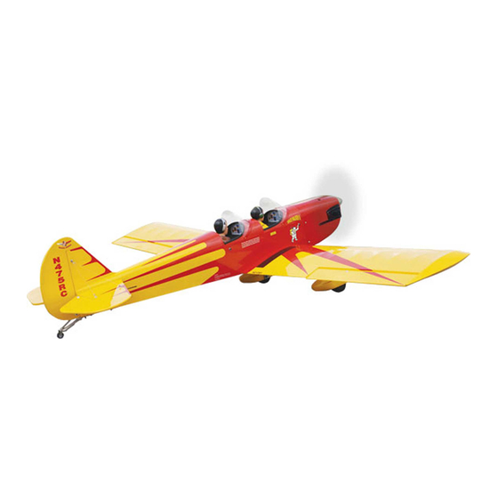
Hand-made Almost Ready to Fly R/C Model Aircraft
"Graphics and specfications may change without notice".
Specifications
Wingspan---------------------------------------- 82.7 in------------------------- 210cm.
Wing area----------------------------------- 1086 sq.in--------------------- 70 sq.dm.
Approximate flying weight------------------ 11 lbs------------------------------- 5kg.
Length-------------------------------------------- 58.7in------------ -------------- 149cm.
Recommended engine size---------- .1.2-1.5 cu.in--------------------- 4-stroke.
Radio System required 4 channels with 6 digital servos/karbonite
or metal gear.
Flying skill level Intermediate/advanced.
Kit features.
•
Ready-made—minimal assembly & finishing required.
•
Ready-covered covering.
•
Photo-illustrated step-by-step Assembly Manual.
Made in Vietnam.
ASSEMBLY MANUAL
MS: 61
Advertisement
Table of Contents

Related Manuals for Seagull Models SPACE WALKER II


Summary of Contents for Seagull Models SPACE WALKER II
-
Page 1: Specifications
Hand-made Almost Ready to Fly R/C Model Aircraft MS: 61 ASSEMBLY MANUAL “Graphics and specfications may change without notice”. Specifications Wingspan---------------------------------------- 82.7 in------------------------- 210cm. Wing area----------------------------------- 1086 sq.in--------------------- 70 sq.dm. Approximate flying weight------------------ 11 lbs------------------------------- 5kg. Length-------------------------------------------- 58.7in------------ -------------- 149cm. Recommended engine size---------- .1.2-1.5 cu.in--------------------- 4-stroke. -
Page 2: Fuselage Assembly
. Flying the SPACE WALKER II is simply a joy. This instruction manual is designed to help you build a great flying aeroplane. Please read this manual thoroughly before starting assembly of your SPACE WALKER II . Use the parts listing below to identify all parts. -
Page 3: Hinging The Ailerons
Hinge. gluing! This will ensure proper as- sembly as the SPACE WALKER II is made from natural materials and 3) Slide the wing panel on the aileron until minor adjustments may have to be there is only a slight gap. -
Page 4: Engine Mount Installation
SPACE WALKER II Instruction Manual 5) Turn the wing panel over and deflect the aileron in the opposite direction from the opposite side. Apply thin C/A glue to each hinge, making sure that the C/A penetrates into both the aileron and wing panel. -
Page 5: Installing The Stopper Assembly
www.seagullmodels.com Vent tube. Fuel pick up tube. INSTALLING THE STOPPER ASSEMBLY. Fuel fill tube. 1) Using a modeling knife, carefully cut Carefully use a lighter or heat gun to off the rear portion of one of the 3 nylon tubes permenently set the angle of the vent tube. - Page 6 SPACE WALKER II Instruction Manual Fuel tank. Rubber band. Lite -Plywood Vent tube. block. Wheel Collar. Landing Gear. Axle. Nut. Wheel. Nut. (2) Washer. Fuel fill tube. Wheel Pant. Fuel pick-up tube. Blow through one of the lines to ensure the fuel lines have not become kinked in- side the fuel tank compartment.
-
Page 7: Installing The Main Landing Gear
www.seagullmodels.com LANDING GEAR FAIRING Lite-plywood block. 3x10mm. (4 pcs). Landing gear fairing. 3) A drop of C/A glue on the wheel collar screws will help keep them from coming lose during operation. Repeat the process for the other wheel. INSTALLING THE MAIN LANDING GEAR. 1) The blind nuts for securing the landing gear are already mounted inside the fuselage. -
Page 8: Mounting The Engine
SPACE WALKER II Instruction Manual Pushrod wire. MOUNTING THE ENGINE. 1) Install the pushrod housing through the predrilled hole in the firewall and into the servo compartment. The pushrod housing should protrude 1/4" out past the front of the firewall. - Page 9 www.seagullmodels.com DUMMY ENGINE AND SPINNER INSTALLATION. Install the spinner backplate, propeller and Because of the size of the cowl, it may be nec- spinner cone. essary to use a needle valve extension for the high speed needle valve. Make this out of suf- The propeller should not touch any part ficient length 1.5mm wire and install it into the of the spinner cone.
-
Page 10: Horizontal Stabilizer
SPACE WALKER II Instruction Manual INSTALLING THE FUSELAGE SERVO. Loctite secure. Adjustable Servo Because the size of servos differ, you connector. may need to adjust the size of the precut open- ing in the mount. The notch in the sides of the Servo arm. -
Page 11: Vertical Stabilizer Installation
www.seagullmodels.com Double check all of your measurements once 4) With the stabilizer held firmly in place, more before the epoxy cures. Hold the stabi- use a pen and draw lines onto the stabilizer lizer in place with T-pins or masking tape and where it and the fuselage sides meet. - Page 12 SPACE WALKER II Instruction Manual 5) Slide the vertical stabilizer back in place. Using a triangle, check to ensure that the vertical stabilizer is aligned 90º to the hori- zontal stabilizer. Vertical Stabilizer. Horizontal 90º Stabilizer. 3) While holding the vertical stabilizer...
-
Page 13: Installing The Aileron Servos
www.seagullmodels.com Attach the string to the servo lead and INSTALLING THE AILERON SERVOS. carefully thread it though the wing. Once you have thread the lead throught the wing, remove the string so it can use for the other servo Servos. Small weight. -
Page 14: Aileron Control Horn Installation
SPACE WALKER II Instruction Manual Aileron electric. Wing bottom. Plastic tape. M3 lock nut. Repeat the procedure for orther wing M3 control horn. haft. M3 nut. AILERON CONTROL HORN INSTALLATION 2 sets. Aluminium washer. Wing bottom. 3x40mm. Aileron control horn. - Page 15 www.seagullmodels.com Repeat the procedure for the other wing. ELEVATOR - RUDDER CONTROL HORN INSTALLATION. 1) Install the elevator control horn using Elevator the same method as with the aileron control control horn. horns. 2) Position the elevator control horn on the both side of elevator.
-
Page 16: Mounting The Tail Wheel
SPACE WALKER II Instruction Manual Elevator. Throttle. Rudder. Elevator. INSTALLING TAIL STRUST SUPPORT MOUNTING THE TAIL WHEEL. The tail strut system assembly follow pic- tures below. See picture below. M3 x20 mm. 3x25mm. 3 x10 mm. 3x25mm. Spring. 3 x10 mm. - Page 17 www.seagullmodels.com Bottom. Bottom. Bottom. Bottom. Bottom. M3x20mm.
- Page 18 SPACE WALKER II Instruction Manual INSTALLATION PILOT. Battery. 2x8mm. Receiver. 60mm. 60mm. Antenna. Silicon glue. Silicon glue. ATTACHMENT WING-FUSELAGE. Attach the aluminium tube into fuselage. Machine Screw 2 x 8mm. 15mm. 15mm. Silicon glue pilot. Insert two wing panels as pictures below.
-
Page 19: Control Throws
CONTROL THROWS. wing bolt. 1) We highly recommend setting up the SPACE WALKER II using the control throws listed at right. We have listed control throws for both Low Rate (initial test flying/sport fly- ing) and High Rate (aerobatic flying). -
Page 20: Preflight Check
2) Check every bolt and every glue joint We wish you many safe and enjoyable in the SPACE WALKER II to ensure that ev- flights with your SPACE WALKER II erything is tight and well bonded.
Need help?
Do you have a question about the SPACE WALKER II and is the answer not in the manual?
Questions and answers