Table of Contents
Advertisement
Advertisement
Table of Contents

Related Manuals for Vertiv MPH2


Summary of Contents for Vertiv MPH2
- Page 1 Vertiv™ MPH2™ Rack PDU Installer/User Guide...
- Page 2 Technical Support Site If you encounter any installation or operational issues with your product, check the pertinent section of this manual to see if the issue can be resolved by following outlined procedures. Visit https://www.VertivCo.com/en-us/support/ for additional assistance.
-
Page 3: Table Of Contents
3.1.1 Attaching Input-power Cords without Conduit 3.1.2 Attaching Input-power Cords with Conduit 3.2 Tool-less Mounting 3.3 Installing a MPH2™ Rack PDU in a Vertiv™® Rack 3.3.1 Mounting Hardware and Tools Required 3.3.2 Mounting the Vertical MPH2™ Rack PDU 3.3.3 Mounting the Horizontal MPH2™ Rack PDU 3.3.4 Mounting a Horizontal MPH2™... - Page 4 4.5 View Branch-level Information 4.6 View Receptacle-level Information 4.7 View Sensor Information 4.8 Opening and Closing Circuit Breakers Appendices Appendix A: Specifications Appendix B: Troubleshooting Appendix C: Additional Troubleshooting by Plug Type Vertiv | Vertiv™ MPH2 Rack PDU Installer/User Guide |...
-
Page 5: Important Safety Instructions
SAVE THESE INSTRUCTIONS This safety sheet contains important safety instructions. Read all safety, installation and operating instructions before installing the Vertiv™ MPH2™ Rack Power Distribution Unit (PDU). Adhere to all warnings on the unit and in this safety sheet. Follow all instructions. -
Page 6: Installation Recommendations
WARNING! Opening or removing end caps from an MPH2™ Rack PDU may expose personnel to lethal voltages within the rack PDU. Observe all cautions and warnings. Failure to do so may result in serious injury or death. MPH2™ Rack PDU units contain no user-serviceable parts. For service or technical support, contact Vertiv™... - Page 7 For information regarding the disposal of this equipment, go to http://www.VertivCo.eu. ROHS Compliance The MPH2™ Rack PDU modules comply with the Restriction of Hazardous Substances directive (ROHS), prohibiting use of six hazardous materials manufacturing of electronics, including lead- free solder.
-
Page 8: Safety Symbols
Indicates the principal On/Off switch is in the Off position. Protective Grounding Terminal Indicates a terminal that must be connected to earth ground before any other connections to the equipment may be made. Vertiv | Vertiv™ MPH2 Rack PDU Installer/User Guide... -
Page 9: Introduction
2 INTRODUCTION The Vertiv™ MPH2™ Rack PDU is an intelligent, high-availability line of managed rack PDUs. It offers remote monitoring and control capabilities as well as environmental sensors with multiple power input selections and output configurations. 2.1 Metering Levels Four types of rack PDUs are available that provide metering and status of important electrical parameters for input, branch and receptacle levels, as well as integration with environmental sensors. - Page 10 ITEM DESCRIPTION ITEM DESCRIPTION Vertical rack PDU Serial appliance Connected equipment RPC basic display module (BDM) Case ventilation, both sides (Optional) Monitoring station Rack PDU array Network connection (10 MB/100 MB/1 GB) Sensors—integrated and modular Vertiv | Vertiv™ MPH2 Rack PDU Installer/User Guide...
-
Page 11: General Characteristics
Receptacle types include NEMA 5-20, IEC 60320 C13 and IEC 60320 C19. • Input power connection supports a highly flexible fixed power cord or hard-wired connection to the user accessible terminal block. Vertiv | Vertiv™ MPH2 Rack PDU Installer/User Guide... -
Page 12: Model Types
2.7 Model Types There are four types of Vertiv™ MPH2™ Rack PDU. All models provide power distribution and include input and branch metering. • Type B Rack PDU metered: Provides metering of input and branches. • Type C Rack PDU metered, receptacle-switched: Provides metering of input and branches and individual power on/off control of each receptacle. -
Page 13: On-Board Lcd Controls And Indicators
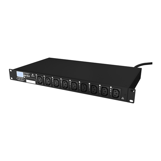
LEDs at their receptacles. Figure 2.4 Type B Rack PDU Model Example Table 2.4 Type B Rack PDU Model Example Descriptions ITEM DESCRIPTION Branch identification Receptacle identification Figure 2.5 Type R Rack PDU Model Example Vertiv | Vertiv™ MPH2 Rack PDU Installer/User Guide... -
Page 14: Branch Overcurrent Protection
Depending upon region and model, PDUs may also have labeling showing the phase associated with each circuit breaker. NOTE: The branch circuit breaker is not designed to be used as a disconnect device for the connected load. Figure 2.6 Circuit Breaker Branch Identification Vertiv | Vertiv™ MPH2 Rack PDU Installer/User Guide... -
Page 15: Hard-Wired Connection Features
A collar secures the input wire, providing stain relief for the terminal block connections. See Disassembly to install an input-power cable on page 14. Vertiv | Vertiv™ MPH2 Rack PDU Installer/User Guide... - Page 16 This page intentionally left blank. Vertiv | Vertiv™ MPH2 Rack PDU Installer/User Guide...
-
Page 17: Installation
9. Replace the terminal block cover by either sliding it on or snapping it into place. 10. Reattach the end cap to the MPH2™ Rack PDU with the two screws removed in step 1. Vertiv | Vertiv™ MPH2 Rack PDU Installer/User Guide... -
Page 18: Attaching Input-Power Cords With Conduit
8. Install the terminal block cover, by either sliding it on or snapping it into place and sliding it firmly against the main body of the MPH2™ Rack PDU. 9. Attach the metal end plate to the MPH2™ Rack PDU with four screws provided in the kit. Vertiv | Vertiv™ MPH2 Rack PDU Installer/User Guide... - Page 19 Conduit connector (field-supplied) and locknut Terminal block Conduit (cable not shown) Table 3.1 Hard-wired models—Recommended Wiring Sizes MPH2™ RACK PDU INPUT CURRENT RATING UNITS ≤32 A >32 A ² 10 mm Metric 4 mm² Imperial (US Standard) 10 AWG 6 AWG Vertiv | Vertiv™ MPH2 Rack PDU Installer/User Guide...
-
Page 20: Tool-Less Mounting
3.2 Tool-less Mounting For tool-less mounting, attach the mounts to the rear of the MPH2™ Rack PDU, then hang it in the rack as shown in the following figure. Tighten the screw attaching the mounting button to 17.7 lb-in. (2 Nm). -
Page 21: Mounting The Vertical Mph2™ Rack Pdu
Level 3.3.2 Mounting the Vertical MPH2™ Rack PDU The vertical MPH2™ Rack PDU can be installed on a vertical or horizontal frame member in the rack. Determine where in the rack the PDU will be installed. 2. Attach a bracket to each end of the PDU. -
Page 22: Mounting A Horizontal Mph2™ Rack Pdu On Vertical Frame Member With Aluminum Extrusions
Choose a position in the rack for the PDU and install four spring nuts into the groove. 2. Use a level to check if the horizontal plane is maintained. 3. Set the distance to match the holes on the PDU, and hold the MPH2™ Rack PDU over the desired position (now with the spring nuts). -
Page 23: Rack Grounding Strap
Vertiv™’s MPH2™ Rack PDU. Units with factory-attached input-power cords have a grounding conductor internal to the case. The rack grounding strap establishes the same ground potential between the MPH2™ Rack PDU and the rack enclosure. -
Page 24: Recommended Input Branch Circuit Protection
— — To connect a ground-strap to the rack: Insert a spring nut into the rack frame near the grounding point on the MPH2™ Rack PDU (see Tool-less mounting on page 16 for inserting the spring nut). 2. Attach a ground wire to the rack with a screw, washer and lock washer. The screw is secured to the rack’s frame with a spring nut. -
Page 25: Connecting Rack Equipment
Make sure that input power is installed in accordance with national and local electric codes. 2. Verify that all equipment is turned off. 3. If the MPH2™ Rack PDU will be monitored over a network, connect an Ethernet cable to the Network port on the RPC2. -
Page 26: Installing Optional Items
MPH2™ Rack PDUs. Display information is accessed via a navigation switch on the BDM. The RPC BDM is connected by cable to the MPH2™ Rack PDU, allowing the user to install the display to suit the local reading preferences. A 6.5-ft. (2-m) cable and general mounting provisions are provided. - Page 27 3. Insert the MPH2™ Rack PDU screw into the spacer sleeve. 4. Insert the MPH2™ Rack PDU screw into the spring nut and tighten securely with a flat-head screwdriver. 5. Hang the RPC BDM on the screw with the hooded mounting slot on the back of the RPC BDM.
-
Page 28: Temperature/Humidity Sensor Installation
3. Choose where in the rack to install the sensor assembly. NOTE: Vertiv™ recommends placing the sensor in the area of the rack that is likely to be warmest. That location helps determine extreme conditions that can cause equipment damage. -
Page 29: Operation
MPH2™ Rack PDU, such as firmware version, unit rating, model number and serial number. LEDs on the MPH2™ Rack PDU and an audible alarm also assist in providing alerts about events and alarm conditions. The keys under the on-board LCD are used to navigate to various information and to silence alarms. -
Page 30: View Input-Level Information
4.2 View Input-level Information When the MPH2 is first turned on, the input level information of the main screen is shown on the display. NOTE: If no key has been pressed after five minutes, the on-board LCD returns to the main screen. -
Page 31: View Mph2™ Rack Pdu System Information
4.3 View MPH2™ Rack PDU System Information Use the arrow keys to highlight the Information icon. 2. Press the Select key to view the MPH2™ Rack PDU model number, serial number, firmware version, power rating and number of receptacles. Figure 4.4 System information NOTE: The firmware version and other information in the preceding figure are examples only. -
Page 32: Rebooting
5. At the confirmation screen, use the arrow keys to highlight the up or down arrow, and press the Select key to highlight Yes/Reboot Now, then press the Select key to reboot the system. Vertiv | Vertiv™ MPH2 Rack PDU Installer/User Guide... -
Page 33: Restore System Defaults
Figure 4.9 Restore Defaults Confirmation When the "Restore to Factory Defaults" command is initiated via the RPC2 module clients, the MPH2 rack PDU settings are returned to the factory default values as well. NOTE: For detailed information about settings and about network- and protocol-related default settings for the RPC2 module, see the RPC2 Communications Module Installer/User Guide. - Page 34 Delay before RPC2 issues command to power off Post Off Delay seconds receptacle. Unconditionally applies regardless of locked/unlocked and Software Over Temperature loaded/unloaded status. Disabled — Protection (SWOTP) At least one temperature sensor is required. Vertiv | Vertiv™ MPH2 Rack PDU Installer/User Guide...
-
Page 35: Determine Ip Address, Mac Address And Firmware Version
Press any key to activate the display. 2. Use the arrow keys to highlight the Information icon, and press the Select key. 3. Use the arrow keys to highlight the Contrast icon, and press the Select key. Vertiv | Vertiv™ MPH2 Rack PDU Installer/User Guide... -
Page 36: Adjust The Orientation Of The On-Board Display
NOTE: These steps also apply to the RPC BDM. 4.3.6 Adjust the Orientation of the On-board display Because mounting of the MPH2™ Rack PDU in the rack may vary, the on-board display may be “flipped” to change the screen orientation for viewing ease. -
Page 37: View Branch-Level Information
O = open circuit breaker Branches (two shown, A and B) 4.6 View Receptacle-level Information At the input-level (main) screen, highlight the Receptacle icon, and press the Select key to display the receptacle list. Vertiv | Vertiv™ MPH2 Rack PDU Installer/User Guide... - Page 38 To display more details about the selected receptacle, highlight the Information icon and press the Select key. • To return to the previous level view, highlight the Return icon and press the Select key. Figure 4.14 Receptacle information Vertiv | Vertiv™ MPH2 Rack PDU Installer/User Guide...
-
Page 39: View Sensor Information
NOTE: The default label is the sensor’s serial number, but can be changed through the Web interface. Figure 4.15 Sensor List Example NUMBER DESCRIPTION Sensors connected to the MPH2™ Rack PDU. (two temperature sensors and one humidity sensor in the example) Vertiv | Vertiv™ MPH2 Rack PDU Installer/User Guide... -
Page 40: Opening And Closing Circuit Breakers
Figure 4.17 Manually Changing a Circuit Breaker State Table 4.2 Manually Changing a Circuit Breaker State Descriptions NUMBER DESCRIPTION Low-profile breaker switch Standard-profile breaker switch Flat-blade screw driver. To trip breaker (low- or standard-profile), press screw Vertiv | Vertiv™ MPH2 Rack PDU Installer/User Guide... - Page 41 NUMBER DESCRIPTION driver into slot. Press here to reset low-profile breaker. Push top of breaker switch in to reset standard-profile breaker. Vertiv | Vertiv™ MPH2 Rack PDU Installer/User Guide...
- Page 42 This page intentionally left blank. Vertiv | Vertiv™ MPH2 Rack PDU Installer/User Guide...
-
Page 43: Appendices
Universal mounting bracket Low-profile: 2.2 x 1.96 (56 x 50) Width x Depth Inches (mm) 1.73 x 9.84 (44 x 250) 3.46 x 9.84 (88 x 250) Standard: 2.2 x 2.7 (56 x 69) Vertiv | Vertiv™ MPH2 Rack PDU Installer/User Guide... - Page 44 Note: A temporary loss of touch-key functionality may occur for sufficiently large radio-frequency fields induced through the input power-supply cord. Agency Approvals (vary by model UL, cUL, CE, BV, CB, RoHS, REACH, WEEE and region) Vertiv | Vertiv™ MPH2 Rack PDU Installer/User Guide...
-
Page 45: Appendix B: Troubleshooting
Check for changing load conditions. Slow — Overcurrent (All Check overcurrent warning threshold settings. Warning LEDs) Branch Check for changing load conditions. ü Fast Overcurrent (All Check overcurrent alarm threshold settings. Alarm LEDs) Vertiv | Vertiv™ MPH2 Rack PDU Installer/User Guide... - Page 46 Check power source and input plug’s receptacle wiring. Check receptacle power control settings. Check power source for power quality problem. If the MPH2™ Rack PDU uses 3-phase Line power, a single low-voltage phase may cause one or more undervoltage alarms. The ü...
-
Page 47: Appendix C: Additional Troubleshooting By Plug Type
3P5W 16A IEC 60309 ü ü ü ü 3P5W L1-N L2-N L3-N L1-N L2-N L3-N 3P5W 32A IEC 60309 ü ü ü ü 3P4W L1-L2 L2-L3 L3-L1 L1-L2 L2-L3 L3-L1 3P4W 60A Vertiv | Vertiv™ MPH2 Rack PDU Installer/User Guide... - Page 48 This page intentionally left blank. Vertiv | Vertiv™ MPH2 Rack PDU Installer/User Guide...
- Page 50 VertivCo.com | Vertiv Headquarters, 1050 Dearborn Drive, Columbus, OH, 43085, USA © 2017 Vertiv Co. All rights reserved. Vertiv and the Vertiv logo are trademarks or registered trademarks of Vertiv Co. All other names and logos referred to are trade names, trademarks or registered trademarks of their respective owners. While every precaution has been taken to ensure accuracy and completeness herein, Vertiv Co.
Need help?
Do you have a question about the MPH2 and is the answer not in the manual?
Questions and answers