Table of Contents
Advertisement
Quick Links
Advertisement
Table of Contents

Related Manuals for Vertiv CoolChip 1-Phase Fluid Network In-Rack Manifold


Summary of Contents for Vertiv CoolChip 1-Phase Fluid Network In-Rack Manifold
- Page 1 CoolChip 1-Phase Fluid Network In-Rack Manifold User Manual...
- Page 2 The products covered by this instruction manual are manufactured and/or sold by Vertiv. This document is the property of Vertiv and contains confidential and proprietary information owned by Vertiv. Any copying, use, or disclosure of it without the written permission of Vertiv is strictly prohibited.
-
Page 3: Table Of Contents
4.4.3 Female Socket connection on the CoolChip 1-Phase Fluid Network hose 5 Installation 5.1 Precautions for Installation 5.2 Handling 5.3 Depressurizing 5.4 Hose Inspection 5.5 Installation 5.5.1 Single Configuration Installation 5.5.2 Double Configuration Installation 6 Commissioning Proprietary and Confidential ©2024 Vertiv Group Corp. - Page 4 Vertiv™ CoolChip 1-Phase Fluid Network 6.1 Flushing 6.1.1 Connecting Quick Disconnects 6.1.2 Purging Air 7 Maintenance Proprietary and Confidential © 2024 Vertiv Group Corp.
-
Page 5: Safety Instructions
This manual contains important safety instructions that should be followed during the installation and maintenance of the Vertiv™ CoolChip 1-Phase Fluid Network. Read this manual thoroughly before attempting to install or operate this product. Only skilled people should move, install or service this equipment. - Page 6 For anything related to warranties for this product, please refer to CoolChip 1-Phase Fluid Network SL-71201 Limited Warranty . 1 Safety Instructions Proprietary and Confidential © 2024 Vertiv Group Corp.
-
Page 7: Product Overview
2 Product Overview Vertiv™ CoolChip 1-Phase Fluid Network is an In-Rack Manifold and liquid cooling distribution from secondary fluid network to IT equipment in the rack. This product consists of stainless steel tube, hose assembly with quick disconnects, and brackets for the VR and VE Racks. - Page 8 This Mounting Bracket is factory installed and only applies to the Double configuration for CoolChip 1-Phase Fluid Network Item Description Quantity Item Description Quantity Mounting Bracket for Double In-Rack Button Retention Manifold Configuration M6x8 Torx Screw Button Hanger 2 Product Overview Proprietary and Confidential © 2024 Vertiv Group Corp.
-
Page 9: Accessories
Color coded: Red/ Return, Blue/ Supply Installation Bracket for VE Rack RMKBVE Please refer to QIG SL-71203 NOTE: Please refer to Vertiv™ Quick Installation Guide (QIG) SL-71203 for details of installation in VE Racks. 2 Product Overview Proprietary and Confidential ©2024 Vertiv Group Corp. -
Page 10: Product Specification
77.98 (171.92) 67 (147.1) (7.6) (134.53) 392 (15.4) x 1838 (72.4) x 194 52.67 (116.12) RM134 Manifold Assy In-Rack 36 Ports 9mm ID SP 67.9 (149.69) 57.1 (126) (7.6) 2 Product Overview Proprietary and Confidential © 2024 Vertiv Group Corp. -
Page 11: Product Configuration Selection
The Top and Bottom feed configuration refers to which position the In-Rack Manifold will be fed from, through the hose barb, refer to Figure 2.4 on the next page to have a better understanding of these configurations. 2 Product Overview Proprietary and Confidential ©2024 Vertiv Group Corp. -
Page 12: Double Configuration For Coolchip 1-Phase Fluid Network
NOTE: Side panels and doors removed for visual clarity. NOTE: The 42 and 48 Ports sizes of the CoolChip 1-Phase Fluid Network can also be installed in Top-Bottom positions and Double-Single configurations in their respective rack sizes. 2 Product Overview Proprietary and Confidential © 2024 Vertiv Group Corp. -
Page 13: Single Configuration For Coolchip 1-Phase Fluid Network
Table 2.5 Operating conditions Item Requirement Room Enviroment Storing the unit in its original packing in a clean indoor environment free of dust Operating humidity 10 to 90% RH (non-condensing) 2 Product Overview Proprietary and Confidential ©2024 Vertiv Group Corp. - Page 14 Vertiv™ CoolChip 1-Phase Fluid Network This page intentionally left blank 2 Product Overview Proprietary and Confidential © 2024 Vertiv Group Corp.
-
Page 15: Pre-Installation Preparation
• Carefully inspect all items for visible or concealed damage. • Report damage immediately to the carrier and file a damage claim with a copy sent to Vertiv™ or to your sales representative. 3.2 Installation Tools- Field provided Prepare the following tools for the installation process: •... -
Page 16: Internal Server Cabinet Clearance Requirements
Cap Manifold to Bottom Panel (B) 87.53 (3.4) NOTE: Keep space at least 915 mm (36 in.) from the rear of the rack to the wall or to other obstacles for service clearance. 3 Pre-Installation Preparation Proprietary and Confidential © 2024 Vertiv Group Corp. -
Page 17: Specifications
If the differential pressure indicates that there is build up on the filter, the filter should be removed and cleaned, and the particulate from the filter should be examined to determine the type of particulate in the system. 4 Specifications Proprietary and Confidential ©2024 Vertiv Group Corp. -
Page 18: Weldment Assembly
36.5 (1.44) Minimum Allowable Bend 50 (2) 65 (2.5) 75 (3) 150 (6) Radius 4.3.2 Humidity Requirements • 5 to 93%RH (non-condensing) • 10 to 90 % RH (non-condensing) operational 4 Specifications Proprietary and Confidential © 2024 Vertiv Group Corp. -
Page 19: Wetted Materials
Coupling connection at the CoolChip 1-Phase Fluid Network to either a In-Rack CDU or Secondary Fluid Row Manifold Figure 4.1 FD83 Item Description: mm (in) Closed flow position Open flow position 84 (3.31) 71.6 (2.82) 4 Specifications Proprietary and Confidential ©2024 Vertiv Group Corp. - Page 20 Vertiv™ CoolChip 1-Phase Fluid Network Figure 4.2 FD83 90° Item Description: mm (in) Closed flow position Open flow position 125 (4.92) 71.6 (2.82) 4 Specifications Proprietary and Confidential © 2024 Vertiv Group Corp.
-
Page 21: Male Plug Connection At The Coolchip 1-Phase Fluid Network
Figure 4.3 SCG Male Plug Dimensions Item Description: mm (in) 30.5 (1.2) 15.5 (0.6) Hex: 14 (0.5) Side attached to CoolChip 1-Phase Fluid Network Blue for Supply Color Marking Red for Return 4 Specifications Proprietary and Confidential ©2024 Vertiv Group Corp. -
Page 22: Female Socket Connection On The Coolchip 1-Phase Fluid Network Hose
4.4.3 Female Socket connection on the CoolChip 1-Phase Fluid Network hose Material: Nickel-plated brass Figure 4.4 SCG Female Socket Dimensions Item Description: mm (in) 63.8 (2.5) 18 (0.7) 15.7 (0.6) Connected hose 6 (0.2) 4 Specifications Proprietary and Confidential © 2024 Vertiv Group Corp. -
Page 23: Installation
Inspect all hoses for kinks, bulges or soft spots which might indicate broken or displaced reinforcement. If the hose is kinked upon receiving, inspect the kinked section, and do not use if there are signs of stress (discoloration) or cracks. 5 Installation Proprietary and Confidential ©2024 Vertiv Group Corp. -
Page 24: Installation
For this configuration it is necessary to remove both mounting brackets installed from factory of the In-Rack Manifold Weldment Assembly. Removing the M6 x 8 torx screws (8 screws) with the T30 torx key, will be enough to split the manifolds. Figure 5.1 Remove Mounting Brackets 5 Installation Proprietary and Confidential © 2024 Vertiv Group Corp. - Page 25 Figure 5.2 Fix the Hanger Button in the In-Rack Manifold Bracket NOTE: For 48U Ports In-Rack Manifold the bottom hanger goes in the 4th Port of the In-Rack Manifold welded bracket. 5 Installation Proprietary and Confidential ©2024 Vertiv Group Corp.
- Page 26 CAUTION: All 3 CoolChip 1-Phase Fluid Network sizes have to be carried by at least 2 people for safe installation. NOTE: For the 48 Ports In-Rack Manifold in the 52U Rack the button hanger needs to be installed in the 3rd pattern of the PDU bracket. 5 Installation Proprietary and Confidential © 2024 Vertiv Group Corp.
- Page 27 Figure 5.4 Attach the CoolChip 1-Phase Fluid Network into the Rack NOTE: For the 48U Ports In-Rack Manifold in the 52U Rack the button retention screw needs to be installed in the 3rd pattern of the PDU bracket. 5 Installation Proprietary and Confidential ©2024 Vertiv Group Corp.
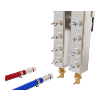
- Page 28 Figure 5.5 Installing Supply or Return hoses on to a CoolChip 1-Phase Fluid Network Item Description Supply Hose Installation (Blue Coded) Return Hose Installation (Red coded) 5 Installation Proprietary and Confidential © 2024 Vertiv Group Corp.
- Page 29 RMK installation position in hose barb RMK installed in hose barb NOTE: To have a better understanding of the opened and closed flow position of the coupling. See Figure 4.1 and Figure 4.2 Specifications 5 Installation Proprietary and Confidential ©2024 Vertiv Group Corp.
-
Page 30: Double Configuration Installation
Inspect the M6x8 torx screws to insure they are fixed to the mounting bracket, if not, use the T30 torx key to tighten them. For this double configuration, the mounting bracket will not have to be removed. Figure 5.7 Inspect the M6 Screws from the Mounting Bracket 5 Installation Proprietary and Confidential © 2024 Vertiv Group Corp. - Page 31 T25 torx key with 50 in-lbs torque. Figure 5.8 Install the Button Hanger in the Mounting Bracket NOTE: For 48U Ports In-Rack Manifold the bottom hanger goes in the 4th Port of the In-Rack Manifold welded bracket. 5 Installation Proprietary and Confidential ©2024 Vertiv Group Corp.
- Page 32 CAUTION: All 3 CoolChip 1-Phase Fluid Network sizes have to be carried by at least 2 people for safe installation. NOTE: For the 48 Ports In-Rack Manifold in the 52U Rack the button hanger needs to be installed in the 3rd pattern of the PDU bracket. 5 Installation Proprietary and Confidential © 2024 Vertiv Group Corp.
- Page 33 Figure 5.10 Attach the CoolChip 1-Phase Fluid Network into the Rack NOTE: For the 48U Ports In-Rack Manifold in the 52U Rack the button retention screw needs to be installed in the 3rd pattern of the PDU bracket. 5 Installation Proprietary and Confidential ©2024 Vertiv Group Corp.
- Page 34 Figure 5.11 Install the Hoses in the CoolChip 1-Phase Fluid Network Assembly Item Description Supply Hose Installation (Blue Coded) Return Hose Installation (Red coded) 5 Installation Proprietary and Confidential © 2024 Vertiv Group Corp.
- Page 35 Remove the Plug G1/4 with the adjustable wrench and install the air bleeder by hand as shown in the figure below. Figure 5.12 Air Bleeder Kit Installation NOTE: The same process applies for the single configuration in both manifolds. 5 Installation Proprietary and Confidential ©2024 Vertiv Group Corp.
- Page 36 FD83 Coupling installation position in hose barb FD83 Coupling installed in hose barb NOTE: To have a better understanding of the opened and closed flow position of the coupling. See Figure 4.1 and Figure 4.2 Specifications 5 Installation Proprietary and Confidential © 2024 Vertiv Group Corp.
-
Page 37: Commissioning
Remove the top plug and install a G¼ male hose (field supply) on the top. • Then fill the In-Rack Manifold trough the hose barb to fill the manifold with same fluid use for secondary system. • Purge all the air. 6 Commissioning Proprietary and Confidential ©2024 Vertiv Group Corp. - Page 38 Vertiv™ CoolChip 1-Phase Fluid Network This page intentionally left blank 6 Commissioning Proprietary and Confidential © 2024 Vertiv Group Corp.
- Page 39 Maintenance should only be carried out by personnel qualified to work on this type of equipment once per year. During Preventive Maintenance check for leaks and/or damage at the drain, air vent, couplings and ports. Test the air vent to make sure there is no blockage. 7 Maintenance Proprietary and Confidential ©2024 Vertiv Group Corp.
- Page 40 Vertiv™ CoolChip 1-Phase Fluid Network This page intentionally left blank 7 Maintenance Proprietary and Confidential © 2024 Vertiv Group Corp.
- Page 41 Vertiv™ CoolChip 1-Phase Fluid Network...
- Page 42 Vertiv.com | Vertiv Headquarters, 1050 Dearborn Drive, Columbus, OH, 43085, USA © 2024 Vertiv Group Corp. All rights reserved. Vertiv™ and the Vertiv logo are trademarks or registered trademarks of Vertiv Group Corp. All other names and logos referred to are trade names, trademarks or registered trademarks of their respective owners. While every precaution has been taken to ensure accuracy and completeness here, Vertiv Group Corp.
Need help?
Do you have a question about the CoolChip 1-Phase Fluid Network In-Rack Manifold and is the answer not in the manual?
Questions and answers