Dimetix DLS-C 15 Technical Reference Manual
Distance laser sensor dls-c series fls-c series
Hide thumbs
Also See for DLS-C 15:
- Technical reference manual (71 pages) ,
- Technical reference manual (42 pages)
Table of Contents

Related Manuals for Dimetix DLS-C 15


Summary of Contents for Dimetix DLS-C 15
- Page 1 Distance Laser Sensor DLS-C 15 / DLS-C 30 DLS-CH 15 / DLS-CH 30 FLS-C 10 / FLS-C 30 FLS-CH 10 / FLS-CH 30 Technical Reference Manual V5.02 Please check www.dimetix.com for the latest version This Manual is Valid for software version 0500 or later...
-
Page 2: Table Of Contents
ECHNICAL EFERENCE ANUAL Table of Contents 1 Introduction........................................4 1.1 Product identification...................................5 1.2 Components......................................5 1.3 Validity.........................................5 2 Application examples....................................6 2.1 Serial interface RS-232 / RS-422................................6 2.2 Analog and digital output..................................6 2.3 External display....................................6 2.4 External trigger....................................6 2.5 SSI connection.....................................7 2.6 Positioning......................................7 3 Device overview and setup....................................8 3.1 Connection for configuration................................8 3.2 Output interfaces....................................9... - Page 3 ECHNICAL EFERENCE ANUAL 7 Physical dimensions.....................................28 8 Factory settings......................................28 8.1 Standard configuration..................................28 8.2 User configured measurement................................28 9 Command set......................................29 9.1 General......................................29 9.1.1 Command termination <trm>..............................29 9.1.2 Device identification N................................29 9.1.3 Parameter separator.................................29 9.1.4 Set/Get commands...................................29 9.1.5 Startup sequence..................................29 9.2 Operation commands..................................30 9.2.1 Distance measurement (sNg)..............................30 9.2.2 Single sensor tracking (sNh)..............................30 9.2.3 Single sensor tracking with timer(sNh).............................30...
-
Page 4: Introduction
Measured distance DLS-C(H) FLS-C(H) Fig. 1 Standard application Key features • Compatible with DIMETIX DLS-B(H) and DLS-A(H) Laser Distance Sensor • Measurement range 0.05 to 500 m • Serial interface (RS-232 and RS-422) • SSI interface (FLS-C(H) only) •... -
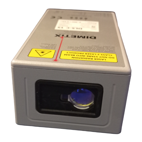
Page 5: Product Identification
The product is identified by the label on the top of the sensor: DLS-C Version with a measurement rate of up to 6 Hz and a maximum measuring distance of 150m Typical Accuracy 1.5mm 3.0mm Standard version DLS-C 15 DLS-C 30 Part No.: 500622 Part No.: 500621 Extended temperature range DLS-CH 15 DLS-CH 30 Part No.: 500624... -
Page 6: Application Examples
Since the configuration of the DLS-C(H)/FLS-C(H) is very flexible the device is usable in various situations. The following application examples give an idea of possible applications. Please visit www.dimetix.com for a detailed description of the mentioned application examples and check for additional application examples. -
Page 7: Ssi Connection
In this applications the FLS-C(H) uses the SSI interface (4.2.6 SSI Possition connection on page 19) and the moving target characteristic (3.4.2 Moving target characteristic on page 13. Please check on www.dimetix.com for detailed application notes. Fig. 7: Positioning application Distance Laser Sensor Page 7/53... -
Page 8: Device Overview And Setup
To be able to configure the DLS-C(H)/FLS-C(H), it must be powered and connected to a PC. Figure 8 shows the necessary connections. On the PC, any terminal program can be used to communicate with the module. A configuration utility is also available on the web page www.dimetix.com. DLS-C(H) -
Page 9: Output Interfaces
ECHNICAL EFERENCE ANUAL 3.2 Output interfaces The DLS-C(H)/FLS-C(H) contains different interfaces. Measurement results and errors are signaled at the outputs as described below. RS-232 The RS-232 is meant for the configuration of the device, however measurement can also be taken using the RS-232 interface. -
Page 10: Operation Modes
Host software is required for operation of the DLS-C(H)/FLS-C(H) in controlled mode. When connecting multiple devices to a single serial line (RS-422), strict Master-Slave communication must be implemented (DLS-C(H)/FLS-C(H) operates as slave). For software sample-code or application-notes please consult our web site www.dimetix.com. Careful testing of the host software together with the devices prior to installation is strongly recommended. -
Page 11: Stand-Alone Mode
ECHNICAL EFERENCE ANUAL 3.3.2 Stand-alone mode Before starting the stand-alone mode, output configuration must be done (See 3.2 Output interfaces on page 9) 3.3.2.1 Auto start configuration The following steps are necessary to configure the DLS-C(H)/FLS-C(H) for stand-alone mode with auto start. Action Comment Command... -
Page 12: Measuring Characteristics
ECHNICAL EFERENCE ANUAL 3.4 Measuring characteristics Multiple measuring characteristics are available in the FLS-C measuring devices to meet different requirements for various applications. With these measuring characteristics measuring rate and accuracy can be optimized for special requirements. The FLS-C measuring device at factory settings has an accuracy of ±1 mm (FLS-C(H) 10) respectively ±3 mm (FLS-C(H) 30) at 2σ. Measuring rate depends on environmental conditions such as target surface, distance, background light (e.g. -
Page 13: Moving Target Characteristic
ECHNICAL EFERENCE ANUAL 3.4.2 Moving target characteristic For continuous movements of a target which typically appears in positioning applications like automatic warehouses there is a special measurement characteristic built into the FLS-C (H) called “Moving target”(See 2.6 Positioning on page 7 for a sample application) moving target jumping target >... -
Page 14: Error Behavior
ECHNICAL EFERENCE ANUAL 3.4.3 Error behavior The device has different error behaviors depending on the measuring characteristics and on the start operation. 3.4.3.1 A - Behavior In case the device detects an error, this error is signalized at the outputs. On the serial and SSI output the error code will be visible depending on the configuration. -
Page 15: Special User Commands
ECHNICAL EFERENCE ANUAL 3.5 Special user commands The standard command set is extended by a special user command set, which makes it possible to change the output format and apply a offset and gain. User command configuration do not influence Analog, Digital and SSI outputs. 3.5.1 Offset / Gain The user can set an individual user gain and offset to create user defined output values. -
Page 16: Output Value Filter
ECHNICAL EFERENCE ANUAL 3.6 Output value filter The DLS-C(H)/FLS-C(H) contains a filter for the measurement value, which can be activated and offers different configurations. This filter is available in the following Measuring characteristics (see 3.4 Measuring characteristics) on the DLS-C(H) and the FLS-C(H): - Normal - Fast - Precise... -
Page 17: Installation
Alignment of the laser beam is often difficult when the target is far away, as the laser spot is not visible. An optional telescopic viewfinder and an alignment jig is available to simplify the alignment procedure. (See www.dimetix.com for additional accessories and further details). -
Page 18: Serial Connection
ECHNICAL EFERENCE ANUAL 4.2.4 Serial connection This connection is mainly used for the controlled mode or to configure the device. RS-232 Only point-to-point communication is possible when using the RS-232 interface. Never connect multiple DLS-C(H)/FLS-C(H)s on a RS-232 serial line DLS-B(H) DLS-C(H) Host... -
Page 19: Analog / Digital Connection
ECHNICAL EFERENCE ANUAL 4.2.5 Analog / Digital connection This connection is mainly used with the stand-alone mode. The analog interface of the DLS-C(H)/FLS-C(H) is isolated from the rest of the device (See 4.2.3 Shield and ground on page 17). When using the analog interface, connect the analog ground (AGND). Make sure, that the total resistance in the analog path is lower than 500 Ω. -
Page 20: External Trigger Connection
ECHNICAL EFERENCE ANUAL 4.2.7 External trigger connection The DO1 (Digital Output 1) can also be used as digital input. For safety reasons, always use a resistor to protect the connection terminal. The function of digital input can be configured by the command sNDI1 (see 9.3.8 Configure digital input (sNDI1) on page 38) DLS-C(H) DO/DI 1... -
Page 21: Technical Data
ECHNICAL EFERENCE ANUAL 5 Technical data 5.1 Measuring accuracy definition The measuring accuracy corresponds to the ISO-recommendation ISO/R 1938-1971 with σ, 99.7% a statistical confidence level of 95.4% (i.e. ± twice the standard deviation refer to diagram on the right). The typical measuring accuracy relates to average conditions for measuring. -
Page 22: Prevention Of Erroneous Measurements
5.3.1 Rough surfaces On a rough surface (e.g. coarse plaster), measure against the center of the illuminated area. To avoid measuring to the bottom of gaps in the surface use a target plate (see accessories on www.dimetix.com) or board. 5.3.2 Transparent surfaces To avoid measuring errors, do not measure against transparent surfaces such as colorless liquids (such as water) or (dust-free) glass. -
Page 23: Specifications
Dimensions 150 x 80 x 55 mm Temperature range during operation DLS-C 15 / DLS-C 30 / FLS-C 10 / FLS-C 30 -10 °C to +50 °C DLS-CH 15 / DLS-CH 30 / FLS-CH 10 / FLS-CH 30 -40 °C to +50 °C Temperature range during storage -40 °C to +70 °C... -
Page 24: Electrical Components
ECHNICAL EFERENCE ANUAL 6 Electrical components To open the side cover, a Torx T9 screwdriver is needed. 6.1 ID switch This switch is used to set the Device ID and can be set from 0 to 9. The default setting is 0. 6.2 Reset switch To reset the device to factory settings do the following: •... -
Page 25: Analog Output
ECHNICAL EFERENCE ANUAL 6.5 Analog output The analog output of the DLS-C(H)/FLS-C(H) is a current source (0..20mA or 4..20mA). It is capable of driving loads up to 500 Ω. ( MaxDist −MinDist )∗Accuracy Conf Conf =Accuracy Dist Device Total error in mm MaxDist Configured max Distance in mm Dist... -
Page 26: Ssi Output
ECHNICAL EFERENCE ANUAL 6.8 SSI output The SSI Interface is implemented in the FLS-C(H) only. 6.8.1 SSI Specification SSI parameters Setting for FLS-C(H) Distance output values 0.. 16777215 1/10mm (max. 1.67km) Measurement value coding Binary or gray, MSB first Transmission mode Configurable, 23/24-bit measurement value, error bit, error code Resolution 0.1mm... -
Page 27: Connector
ECHNICAL EFERENCE ANUAL 6.9 Connector 6.9.1 D-Sub connector Designator Description RS-232 receive line RS-232 send line RS-422 send line negative SSI data output negative (for FLS-C(H) if configured for SSI) RS-422 send line positive SSI data output positive (for FLS-C(H) if configured for SSI) RS-422 receive line negative SSI clock input negative (for FLS-C(H) if configured for SSI) RS-422 receive line positive... -
Page 28: Physical Dimensions
ECHNICAL EFERENCE ANUAL 7 Physical dimensions 88.5 38.5 3 x M4 x 5 150.0 M16 x 1.5 37.3 12.2 152.5 Laser Beam 19.0 Measuring reference 80.0 All dimensions in mm 8 Factory settings 8.1 Standard configuration Operation Mode Controlled Serial Communication Setting 7 Baud: 19200... -
Page 29: Command Set
ECHNICAL EFERENCE ANUAL 9 Command set 9.1 General 9.1.1 Command termination <trm> <trm> <cr><lf> All commands for the DLS-C(H)/FLS-C(H) are ASCII based and terminated with 9.1.2 Device identification N Since the device can be addressed with the ID switch, the ID is represented in the commands by At the location of the insert the Device ID. -
Page 30: Operation Commands
ECHNICAL EFERENCE ANUAL 9.2 Operation commands 9.2.1 Distance measurement (sNg) Triggers simple measurement of distance. Each new command cancels an active measurement. Command Command sNg<trm> Return successful gNg+xxxxxxxx<trm> Return error gN@Ezzz<trm> Parameters Device ID xxxxxxxx Distance in 1/10 mm Error code 9.2.2 Single sensor tracking (sNh) Triggers continuous measurements of the distance. -
Page 31: Tracking With Buffering - Start (Snf)
ECHNICAL EFERENCE ANUAL 9.2.4 Tracking with buffering – Start (sNf) Triggers continuous measurements of the distance with internal buffering in the device (buffer for one measurement). The rate of measurements is defined with the sampling time. If the sampling time is set to zero, the measurements are executed as fast as possible (Measuring speed depends on target conditions). -
Page 32: Temperature Measurement (Snt)
ECHNICAL EFERENCE ANUAL 9.2.8 Temperature measurement (sNt) Triggers measurement of the temperature inside the sensor. Command Command sNt<trm> Return successful gNt+xxxxxxxx<trm> Return error gN@Ezzz<trm> Parameters Device ID xxxxxxxx Temperature in 0.1°C Error code 9.2.9 Laser ON (sNo) Switches the laser beam ON for easy adjustment. Command Command sNo<trm>... -
Page 33: Configuration Commands
ECHNICAL EFERENCE ANUAL 9.3 Configuration commands 9.3.1 Set communication parameter (sNbr) Sets the communication parameters for the serial interface. This command saves all configuration parameters to Flash. The changed baud rate is activated after the next power on. Bold = default parameters (first use or after reset) Command Command sNbr+yy<trm>... -
Page 34: Measuring Characteristic Configuration (Snuc)
ECHNICAL EFERENCE ANUAL 9.3.2 Measuring characteristic configuration (sNuc) Multiple measuring characteristic available in the FLS-C measuring devices meet different requirements for various applications. With these measuring characteristics measuring rate and accuracy can be optimized for special requirements. While on factory settings, the FLS-C measuring device has an accuracy of ±1 mm 2σ (FLS-C(H) 10) respectively ±3 mm 2σ (FLS-C(H) 30). Measuring rate depends on environmental conditions such as target surface, distance, background light (e.g. -
Page 35: Set Auto Start Configuration (Sna)
ECHNICAL EFERENCE ANUAL 9.3.3 Set auto start configuration (sNA) This command activates the stand-alone mode with auto start of the DLS-C(H)/FLS-C(H). It triggers continuous measurements of the distance. The analog, digital and SSI outputs are updated according to the measured distance values. The sampling time defines the measurement rate. -
Page 36: Set/Get Analog Output Distance Range (Snv)
ECHNICAL EFERENCE ANUAL 9.3.6 Set/Get analog output distance range (sNv) Sets the minimum and maximum distances corresponding to the minimum and maximum analog output current levels. 0...20mA 4...20mA DIST −D DIST −D Aout= Aout= ∗20mA ∗16mA +4mA −D −D Aout Analog current output DIST Actual measured distance... -
Page 37: Set/Get Digital Output Levels (Snn)
ECHNICAL EFERENCE ANUAL 9.3.7 Set/Get digital output levels (sNn) Sets the distance levels at which the digital outputs are switched ON and OFF with a hysteresis. Two different situations are possible: ON level > OFF level The ON level of the hysteresis is larger than the OFF level. With an increasing distance, the digital output is switched on (open drain output is closed) when closed the distance exceeds the ON level. -
Page 38: Configure Digital Input (Sndi1)
ECHNICAL EFERENCE ANUAL 9.3.8 Configure digital input (sNDI1) The digital output 1 of the DLS-C(H)/FLS-C(H) can also be used as digital input. The command sNDI1 configures an action for the device. sNRI The state of the digital input can be read with the command On active digital input, the digital output function of DO1 is deactivated Set command Get command... -
Page 39: Interface 2 Configuration (Rs-422 / Ssi)
ECHNICAL EFERENCE ANUAL 9.3.10 Interface 2 configuration (RS-422 / SSI) The SSI interface is implemented on the FLS-C(H) device only and deactivated by default. Since the SSI interface uses the same connection as the RS-422 interface only one of these two interface can be used at the same time. Use the stand-alone mode with auto start to automatically update the SSI output value. -
Page 40: Set/Get Error Value On Ssi Output
ECHNICAL EFERENCE ANUAL 9.3.11 Set/Get error value on SSI output In case of an error the SSI output will show a value corresponding to this configuration. There can be a replacement value in a range of 0 to 16777215 (24Bit) or 0 to 8388607 (23Bit), the last valid distance value or the error code. All values are shown either as binary value or gray coded depending on configuration. -
Page 41: Set Configuration Parameters To Factory Default (Snd)
ECHNICAL EFERENCE ANUAL 9.3.14 Set configuration parameters to factory default (sNd) This command restores all configuration parameters to their factory default values. The parameters are written to the Flash Memory and therefore permanently saved. The communication parameters are also reset to factory settings. Command Command sNd<trm>... -
Page 42: Get Device Generation And Type (Dg)
ECHNICAL EFERENCE ANUAL 9.3.17 Get device generation and type (dg) This command returns the device type, generation and current communication settings. Works only from device generation C on. Never use this command if more than one device is connected to the RS-422 line Command Command <trm>... -
Page 43: Special User Operation Commands
ECHNICAL EFERENCE ANUAL 9.4 Special user operation commands The special user commands are user configurable and are an extension to the standard commands. Use these commands carefully and only if you really understand their impact. The syntax of the user commands differ to the standard commands as follows: Standard Commands: sNxx User Commands:... -
Page 44: User Single Sensor Tracking With Timer(Snuh)
ECHNICAL EFERENCE ANUAL 9.4.3 User single sensor tracking with timer(sNuh) This command does the same as the sNuf command, but the unit sends the results directly to the output. This command takes the user distance offset and user gain into account Never use this command if more than one device is connected to the RS-422 line Command sNuh+xxx<trm>... -
Page 45: Special User Configuration Commands
ECHNICAL EFERENCE ANUAL 9.5 Special User configuration commands 9.5.1 Set user auto start configuration (sNuA) This command activates the user stand-alone mode with auto start of the DLS-C(H)/FLS-C(H). It triggers continuous measurement of the distance. The distance output at the serial interface (RS-232 and RS-422) is corrected with the user offset and user gain as set with the command 9.5.2 Set/Get user distance offset (sNuof) and 9.5.3 Set/Get user distance gain (sNuga) on page 45. -
Page 46: User Output Protocol (Snuo)
ECHNICAL EFERENCE ANUAL 9.5.4 User output protocol (sNuo) This command modifies the output for the user configured commands. The output can be configured to fit the requirement of an external display. A parameter for the output mode between 100 and 189 defines the format for an external display. The last digit of the parameter defines the field length for the output number. -
Page 47: Error Codes
Received signal too weak or target lost in moving target characteristic @E255 (Use different target and distances, if the problem persists, please contact Dimetix) Received signal too strong @E256 (Use different target and distances, if the problem persists, please contact Dimetix) -
Page 48: Safety Instructions
Opening of the equipment, except to open the cover for access to the screw terminal Carrying out modification or conversion of the product Operation after failure in operation Use of accessories from other manufacturers without the express approval of Dimetix Aiming directly into the sun Deliberate dazzling of third parties; also in the dark 10) Inadequate safeguards at the surveying location (e.g. -
Page 49: Areas Of Responsibility
Responsibilities of the manufacturer of non-Dimetix accessories: The manufacturers of non-Dimetix accessories for the DLS-C(H)/FLS-C(H) are responsible for developing, implementing and communicating safety concepts for their products. They are also responsible for the effectiveness of these safety concepts in combination with the Dimetix equipment. -
Page 50: Laser Classification
ECHNICAL EFERENCE ANUAL Precautions: Only use this product as a measuring sensor, not as a control device. The system must be configured and operated in such a way that no damage will occur in the event of an erroneous measurement, malfunction of the device or power failure due to installed safety measures (e.g. -
Page 51: Electromagnetic Compatibility (Emc)
10.7 Producer Standards Dimetix hereby certifies that the product has been tested and complies with the specifications as stated in this 'Technical Reference Manual'. The test equipment used is in compliance with national and international standards. This is established by our Quality Management System. -
Page 52: Labeling
All other cleanser or resolvent are not allowed. 10.12 Service If you need to service the device, please contact Dimetix for instructions. CAUTION: The warranty is void if the device is opened except the cover of the screw terminal. Removing the label is also understood as opening. - Page 53 Important Notice Dimetix reserves the right to make corrections, modifications, enhancements, improvements and other changes to its products, documentation and services at any time and to discontinue any product or service without notice. We try to give our best possible effort to provide you with perfect documents, but we can not guarantee for incorrect information.
Need help?
Do you have a question about the DLS-C 15 and is the answer not in the manual?
Questions and answers