
Related Manuals for Dimetix DLS-B 15


Summary of Contents for Dimetix DLS-B 15
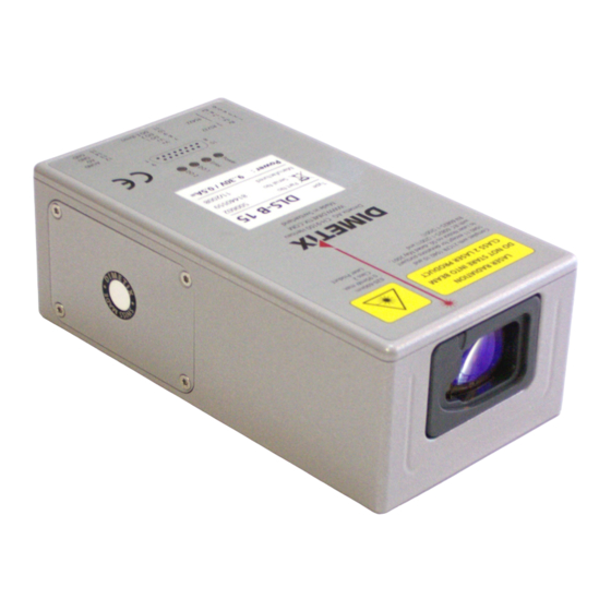
- Page 1 Distance Laser Sensor DLS-B 15 DLS-B 30 DLS-BH 15 DLS-BH 30 Technical Reference Manual V1.02 Please check www.dimetix.com for the latest version...
-
Page 2: Table Of Contents
Table of Contents 1 Introduction..............................3 1.1 Product identification..............................4 1.2 Components................................4 1.3 Validity..................................4 1.4 Measurement range..............................5 1.5 Prevention of erroneous measurements........................5 2 Device setup..............................6 2.1 Connection.................................6 2.2 Controlled mode.................................7 2.3 Automatic mode.................................8 2.4 Display Mode................................9 2.5 External Trigger.................................10 3 Installation.............................. -
Page 3: Introduction
• IP65 (protected against ingress of dust and water) • 4 LEDs for status signaling • Complementary configuration software available at Dimetix web site (www.dimetix.com) • Optional: Internal heater for module operation down to -40°C • Laser class II (<0.95mW) •... -
Page 4: Product Identification
1.1 Product identification The product is identified by the label on the top of the enclosure: Version Typical Accuracy 1.5mm 3.0mm Standard version DLS-B 15 DLS-B 30 Part No.: 500602 Part No.: 500601 Extended temperature range DLS-BH 15 DLS-BH 30 Part No.: 500612... -
Page 5: Measurement Range
ECHNICAL EFERENCE ANUAL 1.4 Measurement range The DLS-B(H) is an optical instrument, whose operation is influenced by environmental conditions. Therefore, the measurement range achieved in use may vary. The following conditions may influence the measurement range: Factors increasing range Factors reducing range Target surface Bright and reflective surfaces such as the Matt and dark surfaces... -
Page 6: Device Setup
To be able to configure the DLS-B(H), it must be powered and connected to a PC. Figure 2 shows the necessary connections. On the PC, any terminal program can be used to communicate with the module. A configuration utility is also available on the web page www.dimetix.com. DLS-B(H) -
Page 7: Controlled Mode
(RS422), strict Master-Slave communication must be implemented (DLS-B(H) operates as slave). For software sample-code or application-notes please consult our web site www.dimetix.com. Careful testing of the host software together with the devices prior to installation is strongly recommended. -
Page 8: Automatic Mode
ECHNICAL EFERENCE ANUAL 2.3 Automatic mode A automatic mode is provided for host-less operation of the DLS-B(H). The analog and digitals outputs are updated according the configuration described below as soon as the unit is powered up. Analog Output The analog output is configurable and works with two ranges: 0..20mA –... -
Page 9: Display Mode
External Displays with a serial interface. Since the DLS-B(H) outputs this formatted string automatically on the serial interface after completing a measurement. Measurement results can be displayed on an external display without an additional controller. For a detailed description of this mode, please contact Dimetix or your dealer. 14,15 RS232 or RS422 Distance Laser Sensor V1.02... -
Page 10: External Trigger
ECHNICAL EFERENCE ANUAL 2.5 External Trigger The DLS-B(H) includes the option of triggering measurements with an external switch or push button on Digital Input 1 (DI 1). Using the Digital Input DI 1 disables the Digital Output DO 1. DLS-B(H) AGND DO/DI 1 The command to activate the external trigger option is described in 8.4 Digital Input on page 30. -
Page 11: Installation
ECHNICAL EFERENCE ANUAL 3 Installation 3.1 Mounting Three M4 threaded holes in the bottom of the DLS-B(H) make it easy to mount the device. Always obey all applicable safety regulations and never use the device outside the specifications stated under 4 Technical data on page 14 3.2 Device wiring 3.2.1 Power Supply... - Page 12 ECHNICAL EFERENCE ANUAL 3.2.4 Controlled mode RS232 Only point-to-point communication is possible when using the RS232 interface. ❢ Never connect multiple DLS-B(H)s on a RS232 serial line DLS-B(H) Host (PC or PLC) 9..30VDC 24..30VDC with Heating 14,15 RS422 It is possible to connect multiple devices on a single RS422 line. To ensure proper operation, strict Master-Slave communication must be applied.
-
Page 13: Alignment Of The Laser Beam
ECHNICAL EFERENCE ANUAL 3.2.5 Automatic mode The analog interface of the DLS-B(H) is isolated from the rest of the device. When using the analog interface, connect the analog ground (AGND). Make sure, that the total resistance in the analog path is lower than 500 Ω. DLS-B(H) Analog Input AGND... -
Page 14: Technical Data
ECHNICAL EFERENCE ANUAL 4 Technical data 4.1 Measuring accuracy The measuring accuracy corresponds to the ISO-recommendation ISO/R 99.7% 1938-1971 with a statistical confidence level of 95.4% (i.e. ± twice the σ 95.4% standard deviation , refer to diagram on the right). The typical measuring accuracy relates to average conditions for measuring. -
Page 15: Specifications
ECHNICAL EFERENCE ANUAL 4.2 Specifications Typical measuring accuracy for DLS-B 15 / DLS-BH 15 ± 1.5 mm @ 2σ DLS-B 30 / DLS-BH 30 ± 3.0 mm @ 2σ Smallest unit displayed 0.1 mm Measuring range on natural surfaces 0.05 to approx. 65 m Measuring range on orange (reflective) target plate. -
Page 16: Electrical Components
ECHNICAL EFERENCE ANUAL 5 Electrical components 5.1 ID switch This switch is used to set the module ID and can be set from 0 to 9. Default setting is 0. 5.2 Reset switch To reset the module to factory settings do the following: Switch OFF the power for the module •... -
Page 17: Connector
ECHNICAL EFERENCE ANUAL 5.6 Connector 5.6.1 D-Sub connector Designator Description RS232 receive line RS232 send line RS422 send line negative RS422 send line positive RS422 receive line negative RS422 receive line positive DC Power + 9V…+30V for DLS-B +24V…+30V for DLS-BH (Heating option) DO 1 Digital output 1 (Open Drain) or Digital input 1 DO 2... -
Page 18: Physical Dimensions
ECHNICAL EFERENCE ANUAL 6 Physical dimensions All dimension in mm 88.5 38.5 3 x M4 x 5 150.0 14.5 36.0 M16 x 1.5 Laser Beam 152.5 Measuring reference 80.0 Distance Laser Sensor V1.02 Page 18/43... -
Page 19: Factory Settings
ECHNICAL EFERENCE ANUAL 7 Factory settings 7.1 Operation Mode: Controlled Mode 7.2 Communication parameters Baud: 19200 Data bit: Parity: Even Stop bit: 7.3 Analog outputs Min output: Range min: Range max: Error output: 7.4 Module ID ID Number: 7.5 Digital output 1 (DOUT1) 2m + 5mm 2005mm OFF:... -
Page 20: Command Set
ECHNICAL EFERENCE ANUAL 8 Command set 8.1 General 8.1.1 Command termination <trm> All commands for the DLS-B(H) are ASCII based and terminated <trm> with <cr><lf>. 8.1.2 Module identification N Since the module can be addressed with the ID switch, the ID is represented in the commands by . -
Page 21: Operation Commands
ECHNICAL EFERENCE ANUAL 8.2 Operation commands 8.2.1 STOP/CLEAR command (sNc) Stops the current execution and resets the status LEDs as well as the digital outputs. Command sNc<trm> Command gN?<trm> Return successful Return Error gN@Ezzz Parameters Module ID Error code 8.2.2 Distance measurement (sNg) Triggers simple measurement of distance. - Page 22 ECHNICAL EFERENCE ANUAL 8.2.4 Temperature measurement (sNt) Triggers measurement of the temperature inside the sensor. Command sNt<trm> Command gNt+xxxxxxxx<trm> Return successful gN@Ezzz Return Error Parameters Module ID xxxxxxxx Temperature in 0.1°C Error code 8.2.5 Laser ON (sNo) Switches laser beam ON for easy adjustment. Command Command sNo<trm>...
- Page 23 ECHNICAL EFERENCE ANUAL 8.2.7 Single sensor Tracking (sNh) Never use this command if more than one module is connected to the RS232/RS422 line Triggers continuous measurement of the distance. This command is not to be used with more then one DLS- B(H) on a RS-232/RS-422 line.
-
Page 24: Configuration Commands
ECHNICAL EFERENCE ANUAL 8.3 Configuration commands 8.3.1 Set/Get communication parameter (sNbr) Sets the communication parameters for the serial interface. This command saves all configuration parameters to Flash. The changed baud rate is activated after the next power on. Bold = default parameters (first use or after reset) Command sNbr+y<trm>... - Page 25 ECHNICAL EFERENCE ANUAL 8.3.2 Set automatic mode (sNA) This command activates the automatic mode of the DLS-B(H). It triggers continuous measurement of the distance and sets the analog and digital outputs according to the measured distance values. The rate of measurements is defined with the sampling time.
- Page 26 ECHNICAL EFERENCE ANUAL 8.3.4 Set/Get analog output value in error case (sNve) This command sets the analog output current level in mA in case of an error. This level can be lower than the minimum level set in 8.3.3 Set/Get analog output min level (sNvm). Set Command Get Command Command...
- Page 27 ECHNICAL EFERENCE ANUAL 8.3.6 Set/Get digital output levels (sNn) Sets the distance levels at which the digital outputs are switched ON and OFF with a hysteresis. Two different situations are possible: ON level > OFF level The ON level of the hysteresis is larger than the OFF level. With an increasing distance, the digital output is switched on (open drain closed output is closed) when the distance exceeds the ON level.
- Page 28 ECHNICAL EFERENCE ANUAL 8.3.7 Save configuration parameters (sNs) This command saves all configuration parameters, which are set by the commands above. The parameters are written to the Flash Memory. Command Command sNs<trm> Return successful gNs?<trm> gN@Ezzz Return Error Parameters Module number (0..9) Error code 8.3.8 Set configuration parameters to factory default (sNd) This command restores all configuration parameters to their factory default values.
- Page 29 ECHNICAL EFERENCE ANUAL 8.3.10 Get Serial Number (sNsn) Retrieves the serial number of the DLS-B(H). Command sNsn<trm> Command +xxxxxxxx<trm> Return successful gNsn gN@Ezzz Return Error Parameters Module number (0..9) xxxxxxxx Serial number of the device Error code Distance Laser Sensor V1.02 Page 29/43...
-
Page 30: Digital Input
ECHNICAL EFERENCE ANUAL 8.4 Digital Input The following commands configure the terminal DO1. This port can also be used as digital input. For safety reasons, always use a resistor to protect the connection terminal. DLS-B(H) DO/DI 1 8.4.1 Configure digital input (sNDI1) The digital output 1 of the DLS-B can also be used as digital input. -
Page 31: Special User Commands
ECHNICAL EFERENCE ANUAL 8.5 Special User Commands The special user commands can be configured by the user and are an extension to the standard commands. Use these commands carefully and only if you really understand what they do. 8.5.1 Set/Get user distance offset (sNuof) The user can set an individual overall offset correction for all distance measurement commands in this 'Special User Command' section. - Page 32 ECHNICAL EFERENCE ANUAL 8.5.3 User-configured single sensor tracking (sNuh) Triggers continuous measurement of the distance and outputs the result immediately to the serial interface. The measured distance is corrected with the user offset (and user gain) as set with the command 8.5.1 Set/Get user distance offset (sNuof).
- Page 33 ECHNICAL EFERENCE ANUAL 8.5.5 Read out – User-configured tracking with buffering (sNuq) After starting “User-configured fast tracking with buffering” with the command sNuf , the last measurement can be read out from the DLS-B(H). This command takes the user distance offset into account Set Command Get Command Command...
-
Page 34: Error Codes
Measurement canceled by user input on serial interface Received signal too weak, distance @E255 (Use different target and distances, if the problem persists, please contact Dimetix) Received signal too strong @E256 (Use different target and distances, if the problem persists, please contact Dimetix) -
Page 35: Accessories
ECHNICAL EFERENCE ANUAL 9 Accessories 9.1 Viewfinder The telescopic viewfinder can be used for easy alignment of the DLS-B(H) for long distances. Clip the support onto the case of the DLS-B(H). Part Number Description 500101 Telescopic viewfinder with DLS-B(H) support 9.2 Target plates The target plates provide a defined measuring target. -
Page 36: Cables
ECHNICAL EFERENCE ANUAL 9.4 Cables Part Number Description PC-Connection cable 3m (configuration cable): 500200 DLS-B to - 9 pin D-Sub for PC (RS232) - 2 wires for power supply RS422-Connection cable 5m: 500203 DLS-B to - 5 wires for RS422 - 2 wires for power supply Connection cable for automatic mode 3m: 500202... -
Page 37: Safety Instructions
5) Carrying out modification or conversion of the product 6) Operation after failure in operation 7) Use of accessories from other manufacturers without the express approval of Dimetix. 8) Aiming directly into the sun 9) Deliberate dazzling of third parties; also in the dark 10) Inadequate safeguards at the surveying location (e.g. -
Page 38: Limits To Use
Responsibilities of the manufacturer of the original equipment Dimetix AG, CH-9100 Herisau (Dimetix): Dimetix is responsible for supplying the product, including the Technical Reference Manual and original accessories, in a completely safe condition. Responsibilities of the manufacturer of non-Dimetix accessories: The manufacturers of non-Dimetix accessories for the DLS-B(H) are responsible for developing, implementing and communicating safety concepts for their products. -
Page 39: Hazards In Use
ECHNICAL EFERENCE ANUAL 10.4 Hazards in use Important hazards in use WARNING: The absence of instruction, or the inadequate provision of instruction, can lead to incorrect or prohibited use, and can give rise to accidents with far-reaching personal, material and environmental consequences. Precautions: All users must follow the safety instructions given by the manufacturer and the directions of the person responsible for the instrument. -
Page 40: Laser Classification
ECHNICAL EFERENCE ANUAL CAUTION: Be careful when pointing a telescope towards the sun, because the telescope functions as a magnifying glass and can injure eyes and/or cause damage inside the DLS-B(H). Precautions: Do not point the telescope directly at the sun. 10.5 Laser classification The DLS-B(H) produces a visible laser beam, which emerges from the front of the instrument. -
Page 41: Electromagnetic Compatibility (Emc)
10.7 Producer Standards Dimetix hereby certifies that the product has been tested and complies with the specifications as stated in this 'Technical Reference Manual'. The test equipment used is in compliance with national and international standards. -
Page 42: Labeling
620-690nm with IEC 60825-1 (2001) and Laser Product EN 60825-1 (2001) Beam divergence 0.16 x 0.6 mrad Pulse duration 0.45x10 Dimetix AG CH-9100 Herisau Max. radiant power 0.95 mW WWW.DIMETIX.COM Made in Switzerland DLS-B 15 Type: Part No.: 500 602 Serial No.:... -
Page 43: Maintenance
Customers should obtain the latest relevant information before placing orders and should verify that such information is up to date and complete. All products are sold subject to Dimetix terms and conditions of sale supplied at the time of order acknowledgment.
Need help?
Do you have a question about the DLS-B 15 and is the answer not in the manual?
Questions and answers