Table of Contents
Advertisement
Quick Links
Laser Distance Sensors
Application Note
AN2019
Moving Target Characteristic with SSI
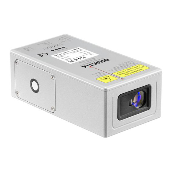
FLS-C
Abstract
The "Moving target characteristic" is made for fast position measuring on continuous moving targets. This
document describes the necessary settings of the FLS-C sensor for the "Moving target characteristic" as well as
the configuration of the SSI and Analog interface.
V1.00
Please check
www.dimetix.com
for the latest version
This application note is provided as is without any warranty for any problems this sample may cause.
Dimetix AG, Degersheimerstrasse 14, CH-9100 Herisau, Switzerland
Phone: +41 71 353 0000, Fax: +41 71 353 0001,
E-mail:
info@dimetix.com
©
www.dimetix.com
Copyright by Dimetix AG
Advertisement
Table of Contents

Related Manuals for Dimetix FLS-C


Summary of Contents for Dimetix FLS-C
- Page 1 The “Moving target characteristic” is made for fast position measuring on continuous moving targets. This document describes the necessary settings of the FLS-C sensor for the "Moving target characteristic" as well as the configuration of the SSI and Analog interface.
-
Page 2: Table Of Contents
Laser Distance Sensors Table of Contents 1 Introduction........................................3 1.1 Feedback positioning...................................3 1.2 Usable sensors.....................................3 2 Preparation........................................4 2.1 Connect DLS/FLS UtilitySW with the FLS-C............................5 3 Measurement characteristic configuration..............................6 4 Interface setup......................................7 4.1 General........................................7 4.2 SSI........................................7 4.2.1 Configuration of the SSI output..............................7 4.2.2 Wiring......................................8... -
Page 3: Introduction
FLS-C for various applications. The FLS-C laser distance sensor is able to measure continuous moving targets with a speed of 200Hz, as long as there are no distance jumps. While the FLS-C is measuring with 200Hz the “SSI” interface is the best choice to transfer the measured results to the host system. -
Page 4: Preparation
24V DC Power supply Download the DLS/FLS UtilitySW from the website http://www.dimetix.com/UtilitySW/ and install it on a PC. Connect the FLS-C sensor to the PC and to the 24V DC Power supply as shown in Fig 2. 14,15 9 pin D-Sub... -
Page 5: Connect Dls/Fls Utilitysw With The Fls-C
Fig. 4. Further the “Status:” field at the bottom will show “OK”. If the DLS/FLS UtilitySW does not show the described information, the connection with the FLS-C is not done properly. If the connection is not done properly, press the reset button and follow the description to reset the sensor. Then make sure that the Port setting is correct and press the “CHECK CONNECTION”... -
Page 6: Measurement Characteristic Configuration
Laser Distance Sensors 3 Measurement characteristic configuration Activate the “Moving target characteristic” to be able to measure with 200Hz. To do so, change to the “Configuration” tab and select the “Measurement characteristic” sub tab on the left, check “Moving target” and press the “DOWNLOAD TO DEVICE”... -
Page 7: Interface Setup
4.2 SSI The FLS-C device contains a SSI interface, that operates as SSI slave. This interface shares the connection pins with the integrated RS422 interface. Hence the RS422 and the SSI interface can not be used at the same time. -
Page 8: Wiring
Laser Distance Sensors 4.2.2 Wiring Never connect the FLS-C to a SSI master before the interface is configured as SSI. Always configure the interface before connecting to the master. SSI slave SSI master FLS-C(H) (i.e. controller) twisted pair connection Clock+... -
Page 9: Analog / Digital
Laser Distance Sensors 4.3 Analog / Digital The analog and digital outputs are updated after each measurement executed by the FLS-C. The scaling of the analog output and the switching limits of the digital outputs can be configured with the DLS/FLS UtilitySW. -
Page 10: Configuration Of The Digital Output
On the “Configuration” tab, select the “Digital output” sub tab on the left and set the values as shown in Fig. 9. After configuring all options press the “DOWNLOAD TO DEVICE” button to save the settings in the FLS-C. If you use manual start (see 5.2 Manual start), digital output 1 can not be used, since this pin will be used as digital input to trigger the measurement. -
Page 11: Measurement Mode
“ON” box and set the “Sample time” input field to 0 sec for fastest possible measurement. As soon as you press the “DOWNLOAD TO DEVICE” button, the device starts to measure. Now the FLS-C is configured to start measuring every time after power on. -
Page 12: Manual Start
Laser Distance Sensors 5.2 Manual start In Manual start operation, the measurement is controlled be the digital input of the FLS-C. The function of the digital input can be configured with the DLS/FLS UtilitySW as shown in Fig. 12. Fig. 12: Manual start configuration (Digital input) On the “Stand-alone Mode”...
Need help?
Do you have a question about the FLS-C and is the answer not in the manual?
Questions and answers