
Related Manuals for Lightware MODEX-F15-OPTS-TX


Summary of Contents for Lightware MODEX-F15-OPTS-TX
- Page 1 User’s Manual MODEX-F15-OPTS-TX MODEX-F15-OPTM-TX MODEX-F15-OPTS-RX MODEX-F15-OPTM-RX Modular Fiber Optical Multimedia Extender...
-
Page 2: Important Safety Instructions
MODEX-F15-OPTS, MODEX-F15-OPTM series – User's Manual Important Safety Instructions Waste Electrical & Electronic Equipment Common Safety Symbols WEEE Class I apparatus construction. This marking shown on the product or its literature, This equipment must be used with a mains power system with a Symbol Description indicates that it should not be disposed with other... -
Page 3: Modex-F15-Opts, Modex-F15-Optm Series – User's Manual
Hardware/Firmware/Software environment: recommended to read and keep in every case! Item Version Lightware Device Controller (LDC) software 1.20.0b5 ATTENTION! Useful information to perform a successful procedure; it is recommended to read. Lightware Device Updater (LDU) software 1.4.0b3 Controller firmware 2.1.1b2... -
Page 4: Table Of Contents
MODEX-F15-OPTS, MODEX-F15-OPTM series – User's Manual Table of Contents 3.10. Video Interface.................20 1. INTRODUCTION ...................6 5. SOFTWARE CONTROL – LIGHTWARE BUILT-IN WEB ....30 3.10.1. Video Inputs in MODEX Transmitters .......... 20 1.1. Box Contents ................6 5.1. Establishing the Connection .............30 3.10.2. Video Outputs in MODEX Receivers ..........20 1.2. Description ...................6... - Page 5 10.4.2. Types of Serial Cables ..............85 7.5.7. Restore the Factory Default Settings ..........56 7.8.8. Change the Gateway Address (Static) .......... 66 10.4.3. RS-232 Signal Transmission over Lightware Extender Devices 85 7.6. Video Port and Crosspoint Settings .........57 7.8.9. Apply Network Settings ..............66 11. APPENDIX ..................86 7.6.1. Query the Video Crosspoint Setting ..........
-
Page 6: Introduction
I ntroduction Model number Transmitter/Receiver MODEX-F15-OPTS-TX Thank you for choosing MODEX, Lightware’s Modular Extender family. In the first chapter we would like to introduce the device highlighting the most Power cable with important features in the below listed sections: Neutrik powerCON... -
Page 7: Typical Application
1. Introduction MODEX-F15-OPTS, MODEX-F15-OPTM series – User's Manual 1.4. Typical Application Wide Range of Interface Modules Integrated System Diagram There are two slots in the extenders where interface modules can be installed. Numerous modules are available which contain Analog-, S/PDIF audio THEATER CONTROL ROOM CINEMA... -
Page 8: Installation
2. Installation MODEX-F15-OPTS, MODEX-F15-OPTM series – User's Manual 2.1. Mounting Options 2.1.2. Truss Mounting (with Mounting Bracket V2) Step 1. Fasten the mounting bracket on the side Devices can be mounted in several ways, depending on the application. of the unit with the provided screws. -
Page 9: Connecting Steps
2. Installation MODEX-F15-OPTS, MODEX-F15-OPTM series – User's Manual 2.2. Connecting Steps Media player Infrared Transmitter side Receiver side Projector Audio amplifier HDMI Audio RS-232 Audio HDMI OPTS / OPTM MODEX MODEX transmitter receiver RS-232 Power Power Keyboard / Ethernet Touch panel Power... -
Page 10: Product Overview
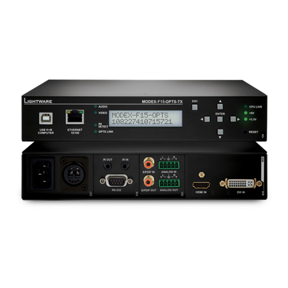
The following sections are about the physical structure of the device, input/ output ports, and connectors: INFO: The photo below depicts a MODEX-F15-OPTS-TX frame. It is almost identical to a MODEX-F15-OPTM-TX frame with two differences: the "OPTM’"designation and the part number. -
Page 11: Receiver
3. Product Overview MODEX-F15-OPTS, MODEX-F15-OPTM series – User's Manual Transmitter Frames Receiver Frames Frame type Part number Frame type Part number MODEX-F15-OPTS-TX 9161 0108 MODEX-F15-OPTS-RX 9161 0109 MODEX-F15-OPTM-TX 9161 0110 MODEX-F15-OPTM-RX 9161 0111 3.1.2. Receiver 3.2. Rear View INFO: The photo below depicts a MODEX-F15-OPTS-RX frame. It is almost identical to a MODEX can be supplied with many kind of interface modules, thus the rear view of the extenders is different. -
Page 12: Media Connectors
3. Product Overview MODEX-F15-OPTS, MODEX-F15-OPTM series – User's Manual 3.3. Media Connectors Module code: MODEX-CON-OPTS-EBCJ Module code: MODEX-CON-OPTM-EBCJ Module code: MODEX-CON-OPTS-EBCM Module code: MODEX-CON-OPTM-NT-PCN Module code:MODEX-CON-OPTS-HF4 Module code:MODEX-CON-OPTM-HF4 Part nr. 9161 0207 Part nr. 9161 0210 Part nr. 9161 0223 Part nr. -
Page 13: Interface Modules
3. Product Overview MODEX-F15-OPTS, MODEX-F15-OPTM series – User's Manual Module code: MODEX-CON-OPTS-NT-BRK-LC Module code: MODEX-CON-OPTM-NT-BRK-LC Module code: MODEX-CON-OPTS-NT-QUAD Module code: MODEX-IF-RS232-IR Module code: MODEX-IF-ETH Module code: MODEX-IF-AUDIN Part nr. 9161 0241* Part nr. 9161 0242 * Part nr. -
Page 14: Video Modules
3. Product Overview MODEX-F15-OPTS, MODEX-F15-OPTM series – User's Manual 3.5. Video Modules 3.5.1. Input Modules Module code: MODEX-IF-ETH-ECN Module code: MODEX-IF-2ETH-RS232 Module code: MODEX-IF-2ETH-RS422* Part nr. 9161 0727 Part nr. 9161 0730 Part nr. 9161 0731 Module code: MODEX-AV-DVIDL-IM Module code: MODEX-AV-HDMI-DVI-IM Module code: MODEX-AV-HDMI-DVI-4K-IM Connector type... -
Page 15: Output Modules
3. Product Overview MODEX-F15-OPTS, MODEX-F15-OPTM series – User's Manual Module code: MODEX-AV-BLANK Module code: MODEX-AV-5HDMI-4K-IM-LH Module code: MODEX-AV-2HDMI-4K-IM-LH Module code: MODEX-AV-DVI-OM* Module code: MODEX-AV-DP-OM Module code: MODEX-AV-DVI-4K-OM Part nr. 9161 0442 Part nr. 9161 0443 Part nr. 9161 0699 Part nr. -
Page 16: Electrical Connections
20-pole DisplayPort connectors for inputs and outputs. Always use high quality DP cable for Phoenix Combicon series (3.5mm pitch, 5-pole), type: MC 1.5/5-ST- Lightware recommends the termination of LAN cables on the basis of ® connecting sources and displays. 3.5. -
Page 17: Ir Connector
3. Product Overview MODEX-F15-OPTS, MODEX-F15-OPTM series – User's Manual 3.6.9. IR Connector Neutrik opticalCON connector (NO2-4FDW type LC duplex) and LC ODVA connector have two fiber channels, channel A and channel B. IR detector and IR emitter can be connected to the receiver with Only one channel is used (from channel A on transmitter to channel B TRS (Tip, Ring, and Sleeve) connectors. -
Page 18: Modular Extender Concept
3. Product Overview MODEX-F15-OPTS, MODEX-F15-OPTM series – User's Manual 3.7. Modular Extender Concept 3.9. Audio Interface Supplied Power Cable The cable is assembled with NAC3FCA Neutrik power connector MODEX extender family is a multifunctional modular transmitter and 3.9.1. Audio Inputs and Modes (Power In) with white chuck that fits for thin cables (diameter between receiver pair with fiber optical connectivity. -
Page 19: Crosspoint Modes
Crosspoint Settings Menu section); ▪ (Audio amplifier and HD TV). ▪ Using the Lightware Device Controller (LDC) (see The Layout of the Crosspoint Menu section); Digital audio signal from the Microphone is transmitted to the Media player as a "reverse direction" ▪... -
Page 20: Video Interface
▪ Using the LCD menu by pressing the navigation buttons (see in Crosspoint Settings Menu section); Flowchart of Autoselection Modes Using the Lightware Device Controller (LDC) (see in Video Layer section); ▪ Automatic Input Selection - Example ▪ Sending LW3 protocol commands (see... -
Page 21: Usb Interface (Kvm Function)
USB device. Thus, the computer will not be aware of any switching in the matrix. Laptop I3 (HDMI IN 3) INFO: You can find the related settings for Lightware Device Controller software in USB KVM Layer section. -
Page 22: Controlling Features
3. Product Overview MODEX-F15-OPTS, MODEX-F15-OPTM series – User's Manual 3.13. Controlling Features Command Injection - Signal Path INFO: You can find the related settings for Lightware Device Controller software in RS-232 Layer section. Transmitter Receiver The control interfaces of MODEX devices can be used to install both 3.13.2. Infrared Interface... -
Page 23: Further Built-In Features
The unit stores EDID of the last device connected to an output, so there is an EDID shown even if there INFO: You can find the related settings for Lightware Device is no display device attached to the output port at the moment. -
Page 24: Operation
4. Operation MODEX-F15-OPTS, MODEX-F15-OPTM series – User's Manual 4.1. Powering On LCD Menu Structure LCD menu Connect the power cord to the device’s IEC C14 standard power input Status connector. The device is immediately powered ON when the power Modules cord is connected to the AC source. -
Page 25: Status Menu
4. Operation MODEX-F15-OPTS, MODEX-F15-OPTM series – User's Manual 4.3. Status Menu 4.4. Link Status Menu 4.5. Crosspoint Settings Menu Status menu has five submenus, you can navigate between them by Link status menu has five submenus, you can navigate between them by Audio and video crosspoint settings are available in this menu. -
Page 26: Audio Ports
4. Operation MODEX-F15-OPTS, MODEX-F15-OPTM series – User's Manual Output Port Settings (O1, O2, ...) ▪ Sampling: information about the sampling of incoming audio signal. ▪ Factory defaults: you can set the Reset settings t Factory defaults: you can set the factory defaults values for the ▪... -
Page 27: Ir Ports
4. Operation MODEX-F15-OPTS, MODEX-F15-OPTM series – User's Manual 4.6.4. IR Ports ▪ Factory defaults: you can set the Dynamic EDID (D). Use the Up and Down buttons to select Reset settings t factory defaults values for the the desired EDID (keep the button pressed to scroll the list ATTENTION! IR port settings are available just in case an IR Enter:Yes Esc:No... -
Page 28: Edid View In The Transmitter And Receiver
4. Operation MODEX-F15-OPTS, MODEX-F15-OPTM series – User's Manual 4.8. Network Settings Menu 4.8.3. Subnet Mask Step 5. Use the Left and Right buttons AllÝF1 ¼ to select EDID group: Factory Step 1. Navigate to the Network settings LWR D640x480p60 If the extender is connected to an Ethernet Network, the settings are ¹Network settin¥... -
Page 29: Apply Settings
4. Operation MODEX-F15-OPTS, MODEX-F15-OPTM series – User's Manual 4.8.5. Apply Settings 4.10.2. Reset the Device Step 2. Select the desired Preset by pressing the Up and Down buttons than press the Enter Step 1. Navigate to the Maintenance / If more modifications happened in the ½Save Preset: Apply settings? -
Page 30: Software Control - Lightware Built-In Web
The controlling features are not so wide ATTENTION! If the connection is made through the Ethernet port as in the case of Lightware Device Contoller, but numerous information is of the router, be sure that the computer is in the same network displayed and many settings are available. -
Page 31: Software Control - Lightware Device Controller
The device can be controlled by a computer through the Ethernet port and down list. instance RS-232 / RS-422 using Lightware Device Controller (LDC). The software can If the proxy settings do not range with the required settings, set ▪... -
Page 32: The Layout Of The Crosspoint Menu
6. Software Control - Using Lightware Device Controller MODEX-F15-OPTS, MODEX-F15-OPTM series – User's Manual Step 3. Select the unit from the discovered Ethernet devices. Double click on the name of the extender or Port Tiles select the device and click on the green Connect button. -
Page 33: Video Layer
6. Software Control - Using Lightware Device Controller MODEX-F15-OPTS, MODEX-F15-OPTM series – User's Manual 6.4. Video Layer 6.4.2. Output Port Properties - Transmitter Click on the optical output port to open the port properties After selecting the Video tab the video crosspoint status is displayed. -
Page 34: Output Port Properties - Receiver
MODEX-F15-OPTS, MODEX-F15-OPTM series – User's Manual 6.4.4. Output Port Properties - Receiver Lightware’s Frame Detector function works like a signal analyzer and makes possible to determine the exact video format that is present on the port, thus helps to identify many problems. E.g. actual timing parameters Click on the desired input port to open the port properties may differ from the expected and this may cause some displays to drop the picture. -
Page 35: Port Properties - Transmitter
6. Software Control - Using Lightware Device Controller MODEX-F15-OPTS, MODEX-F15-OPTM series – User's Manual 6.5.1. Port Properties - Transmitter The Layout of the Crosspoint Menu ▪ Audio mode: Analog / Digital / Mixed; Autoselect settings - see the details below;... -
Page 36: Port Properties - Receiver
6. Software Control - Using Lightware Device Controller MODEX-F15-OPTS, MODEX-F15-OPTM series – User's Manual Analog Audio Settings - Output Output port: Analog Audio Settings - Input The output analog audio settings are available by clicking on the ▪... -
Page 37: Layer
6. Software Control - Using Lightware Device Controller MODEX-F15-OPTS, MODEX-F15-OPTM series – User's Manual 6.6. RS-232 Layer 6.7. Infrared Layer ATTENTION! The layer is available only for the following interface Modules: MODEX-IF-RS232, MODEX-IF- ATTENTION! The layer is available only in case of the following interface Modules: MODEX-IF-RS232-IR 2xRS232, MODEX-IF-RS232-RS422, MODEX-IF-RS232-IR, MODEX-IF-2ETH-RS232. -
Page 38: Usb Kvm Layer
6. Software Control - Using Lightware Device Controller MODEX-F15-OPTS, MODEX-F15-OPTM series – User's Manual Output Port Properties ATTENTION! The USB mode can be set only in the receiver! Clicking on the output port to open the port properties window. -
Page 39: Edid Menu
6. Software Control - Using Lightware Device Controller MODEX-F15-OPTS, MODEX-F15-OPTM series – User's Manual 6.9. EDID Menu 6.9.1. EDID Operations Advanced EDID Management can be accessed by selecting the EDID menu. There are two panels: the left Changing the Emulated EDID one contains Source EDIDs, the right one contains Destination places where the EDIDs can be emulated or Step 1. -
Page 40: Edid Summary Window
EDID and displays it as readable information to the user. All descriptors can be edited, and saved in an EDID file, or uploaded to the User memory. For more details about EDID Editor please visit our website (www.lightware.com) and download the EDID Editor user's manual. EDID Summary Window... -
Page 41: Creating An Edid - Easy Edid Creator
6.9.4. Creating an EDID - Easy EDID Creator 6.10. Control Menu Since the above mentioned Advanced EDID Editor needs more complex knowledge about EDID, Lightware 6.10.1. Ethernet introduced a wizard-like interface for fast and easy EDID creation. With Easy EDID Creator it is possible to create custom EDIDs in four simple steps. -
Page 42: Event Manager
6. Software Control - Using Lightware Device Controller MODEX-F15-OPTS, MODEX-F15-OPTM series – User's Manual 6.10.2. Event Manager 6.11.1. The Event Editor See details about Event Manager in the next section. Press the Edit button in the desired Event line to open the Event editor window. -
Page 43: Create Or Modify An Event
6. Software Control - Using Lightware Device Controller MODEX-F15-OPTS, MODEX-F15-OPTM series – User's Manual 6.11.2. Create or Modify an Event Step 3. Select the desired Property from the menu. The manual of the Enable or Disable an Event... -
Page 44: Clear One Or More Events
6. Software Control - Using Lightware Device Controller MODEX-F15-OPTS, MODEX-F15-OPTM series – User's Manual 6.11.6. Creating and Event - Example TIPS AND TRICKS: The Show advanced expressions option is a Step 2. Set the action. useful tool when you look for the path or value of a property but just... -
Page 45: Settings Menu
6. Software Control - Using Lightware Device Controller MODEX-F15-OPTS, MODEX-F15-OPTM series – User's Manual 6.12. Settings Menu 6.12.2. Network 6.12.1. Status Network tab in Settings menu IP address and DHCP settings can be set on this tab. Always press the Apply settings button to save changes. -
Page 46: System Log
Select the folder where you want to save the report file. The default file name can be changed. This information package can be sent to the Lightware support team when a problem may arise with the device. The Error dump button generates a .bin file which can help our developers to investigate the emerging issues. -
Page 47: Steps In A Nutshell
6. Software Control - Using Lightware Device Controller MODEX-F15-OPTS, MODEX-F15-OPTM series – User's Manual 6.13.4. Create and Restore Backups from the Device Memory Configuration cloning of Lightware LW3 devices is a simple method About the Backup File that eliminates the need to repeatedly configure certain devices to... -
Page 48: Advanced View Window
6. Software Control - Using Lightware Device Controller MODEX-F15-OPTS, MODEX-F15-OPTM series – User's Manual 6.14. Advanced View Window Advanced view is the surface for displaying the LW3 protocol tree. Commands and specific parameters (which are not available on the graphical user interface of the LDC) can be run and set by the controlling tools. -
Page 49: Lw3 Programmers' Reference
MODEX-F15-OPTS, MODEX-F15-OPTM series – User's Manual 7.1. Overview Lightware 3 (LW3) protocol is used by the 25G hybrid matrix, the MODEX family and the new series of Lightware TPS and OPT products. The protocol (LW3) is ASCII-based and all commands are terminated with a carriage return (Cr, ‘\r’) and line feed (Lf, ‘\n’) pair. - Page 50 7. LW3 Programmers’ Reference MODEX-F15-OPTS, MODEX-F15-OPTM series – User's Manual Following example presents the structure of the tree traversal: Example: The following two ones are read-only properties: node1 Path of the nodes: pr●/node1/node12.ReadOnlyProperty=value1 n- /node1 node11 pr●/.DeviceName=25G Hybrid Device n- /node1/node11 node12...
-
Page 51: Escaping
7. LW3 Programmers’ Reference MODEX-F15-OPTS, MODEX-F15-OPTM series – User's Manual 7.1.2. Escaping 7.1.4. Prefix Summary Property values and method parameters can contain characters that are used as control characters in the The following prefixes are defined in the LW3 protocol: protocol. -
Page 52: Lw3 Commands
7. LW3 Programmers’ Reference MODEX-F15-OPTS, MODEX-F15-OPTM series – User's Manual 7.3. LW3 Commands Legend: 7.3.1. Get Command X can be: ‘r’: read-only The ‘GET’ command can be used to get the child nodes, properties and methods of a specific node. It can also be used to get the value of a property. -
Page 53: Set Command
7. LW3 Programmers’ Reference MODEX-F15-OPTS, MODEX-F15-OPTM series – User's Manual 7.3.3. Invocation Example: A method can be invoked with the help of the ‘CALL’ command. ˃ GETALL /EDID Command format: CALL●[nodePath]:[methodName]([parameter]) ˂ n- /EDID/F ˂ n- /EDID/D Response format: ˂... -
Page 54: Manual
7. LW3 Programmers’ Reference MODEX-F15-OPTS, MODEX-F15-OPTM series – User's Manual 7.3.4. Manual Example: For every node, property and method in the tree there is a manual. The manual is a human readable text that ˃ 1103#GET /MEDIA/UART.* describes the syntax and provides a hint for how to use the primitives. -
Page 55: Notifications About The Changes Of The Properties
7. LW3 Programmers’ Reference MODEX-F15-OPTS, MODEX-F15-OPTM series – User's Manual Get the Active Subscriptions for the Current Connection A Short Example of How to Use the Subscription Command format: OPEN In the following, an example is presented, how the subscriptions are working and how to use them. In the example, there are two independent users controlling the device through two independent connections Response format: o-●[nodePath]... -
Page 56: System Commands
7. LW3 Programmers’ Reference MODEX-F15-OPTS, MODEX-F15-OPTM series – User's Manual 7.5. System Commands 7.5.5. Set the Displayed Text on the LCD Screen Two-line long message can be displayed on the LCD screen. 7.5.1. Query the Product Name Command format: CALL●/MANAGEMENT/UI:LcdMenuMessage(<time>;<1stline_text>;<2ndline_text>) The name of the product is a read-only parameter and cannot be modified. -
Page 57: Video Port And Crosspoint Settings
7. LW3 Programmers’ Reference MODEX-F15-OPTS, MODEX-F15-OPTM series – User's Manual 7.6. Video Port and Crosspoint Settings 7.6.4. HDCP Setting (Receiver's Output Port) HDCP capability can be set to Auto/Always on the output ports, non-encrypted content can be transmitted INFO: The settings described in the coming sections and port numbering depend on the installed video to a non-HDCP compliant display. -
Page 58: Query The Status Of Source Ports
7. LW3 Programmers’ Reference MODEX-F15-OPTS, MODEX-F15-OPTM series – User's Manual 7.6.7. Query the Status of Source Ports The Most Common Received Port Status Responses Command format: GET●/MEDIA/VIDEO/XP.SourcePortStatus Response format: pr●/MEDIA/VIDEO/XP.SourcePortStatus=[<I1>;<I2>;…; <In>] T00AA Unlocked, The response contains 5 ASCII characters for each port. The first character indicates the mute/lock state, No embedded Unmuted Reserved... -
Page 59: Query The Status Of Destination Ports
7. LW3 Programmers’ Reference MODEX-F15-OPTS, MODEX-F15-OPTM series – User's Manual 7.6.8. Query the Status of Destination Ports 7.6.10. Change the Autoselect Mode Command format: GET●/MEDIA/VIDEO/XP.DestinationPortStatus Command format: CALL●/MEDIA/VIDEO/XP:setDestinationPortAutoselect(<O >:<O _set>) Response format: pr●/MEDIA/VIDEO/XP.DestinationPortStatus=[<O >;<O >;…; <O >] Response format: mO●/MEDIA/VIDEO/XP.setDestinationPortAutoselect The responses contain one letter and a 2-byte long HEX code showing the current state of the output ports. -
Page 60: Change The Input Port Priority
7. LW3 Programmers’ Reference MODEX-F15-OPTS, MODEX-F15-OPTM series – User's Manual 7.6.12. Change the Input Port Priority 7.6.16. Unlock an Input Port Command format: CALL●/MEDIA/VIDEO/XP:setAutoselectionPriority(<I >\(<O >\):<prio>) Command format: CALL●/MEDIA/VIDEO/XP:unlockSource(<I >) Response format: mO●/MEDIA/VIDEO/XP:unlockSource Response format: mO●/MEDIA/VIDEO/XP:setAutoselectionPrioirty Example: Legend: <prio>: Priority number from 0 to 31, equal numbers are allowed (31 means that the port will be ˃... -
Page 61: Test Pattern Generator
7. LW3 Programmers’ Reference MODEX-F15-OPTS, MODEX-F15-OPTM series – User's Manual 7.6.21. Test Pattern Generator Test Pattern Command format: SET●/MEDIA/VIDEO/<O >.TpgPattern=<pattern> INFO: This setting is available only in case of MODEX-AV-HDMI-DVI-4K-OM module is installed in the MODEX receiver. Response format: pw●/MEDIA/VIDEO/<O >.TpgPattern=<pattern>... -
Page 62: Audio Port And Crosspoint Settings
7. LW3 Programmers’ Reference MODEX-F15-OPTS, MODEX-F15-OPTM series – User's Manual 7.7. Audio Port and Crosspoint Settings The Most Common Received Port Status Responses 7.7.1. Query the Status of Source Port Command format: GET●/MEDIA/AUDIO/XP.SourcePortStatus T000A Unlocked, Response format: pr●/MEDIA/AUDIO/XP.SourcePortStatus=[<I >;<I >;...;<I >]... -
Page 63: Query The Audio Crosspoint Setting
7. LW3 Programmers’ Reference MODEX-F15-OPTS, MODEX-F15-OPTM series – User's Manual 7.7.3. Query the Audio Crosspoint Setting 7.7.5. Change the Autoselect Mode Command format: GET●/MEDIA/AUDIO/XP.DestinationConnectionList Command format: CALL●/MEDIA/AUDIO/XP:setDestinationPortAutoselect(<O >:<O _set>) Response format: pr●/MEDIA/AUDIO/XP.DestinationConnectionList=<I >;...;<I > Response format: mO●/MEDIA/AUDIO/XP.setDestinationPortAutoselect Legend: Legend: see previous section. -
Page 64: Change The Input Port Priority
7. LW3 Programmers’ Reference MODEX-F15-OPTS, MODEX-F15-OPTM series – User's Manual 7.7.7. Change the Input Port Priority 7.7.10. Unmute Audio Input Command format: Command format: CALL●/MEDIA/AUDIO/XP:unmuteSource(<I >) CALL●/MEDIA/AUDIO/XP:setAutoselectionPriority(<I >\(<O >\):<prio>) Response format: mO●/MEDIA/AUDIO/XP:unmuteSource Response format: Example: mO●/MEDIA/AUDIO/XP:setAutoselectionPrioirty ˃ CALL /MEDIA/AUDIO/XP:unmuteSource(I1) Legend: ˂... -
Page 65: Analog Audio Output Level Settings
7. LW3 Programmers’ Reference MODEX-F15-OPTS, MODEX-F15-OPTM series – User's Manual 7.7.14. Analog Audio Output Level Settings Balance Command format: SET●/MEDIA/AUDIO/<I >.Balance=<level> Volume Response format: pw●/MEDIA/AUDIO/<I >.Balance=<level> Command format: SET●/MEDIA/AUDIO/<O >.Volume=<level> Parameters: Response format: pw●/MEDIA/AUDIO/<O >.Volume=<level> <level> Sets the balance; 0 means left balance, 100 means right balance, Parameters: step is 1. -
Page 66: Network Configuration
7. LW3 Programmers’ Reference MODEX-F15-OPTS, MODEX-F15-OPTM series – User's Manual 7.8. Network Configuration 7.8.5. Query the Subnet Mask Command format: GET●/MANAGEMENT/NETWORK.NetworkMask ATTENTION! Please note that all settings below will be applied after calling ApplySettings() method or after the device is restarted next time. See the description of the method in Apply Network Settings Response format: pr●/MANAGEMENT/NETWORK.NetworkMask=<netmask>... -
Page 67: Port Configuration
7. LW3 Programmers’ Reference MODEX-F15-OPTS, MODEX-F15-OPTM series – User's Manual 7.9. RS-232 Port Configuration 7.9.4. Parity Setting Command format: SET●/MEDIA/UART/<P >.Parity=0|1|2|3|4 7.9.1. BAUD Rate Setting Response format: pw●/MEDIA/UART/<P >.Parity=0|1|2|3|4 Command format: SET●/MEDIA/UART/<P >.Baudrate=<Baud_rate> Response format: pw●/MEDIA/UART/<P >.Baudrate=<Baud_rate> Parameters: Parameters: .Parity <Baud_rate>... -
Page 68: Sending Message Via The Communication Ports
7. LW3 Programmers’ Reference MODEX-F15-OPTS, MODEX-F15-OPTM series – User's Manual 7.10. Sending Message via the Communication Ports 7.11. Infrared Port Configuration 7.10.1. Send Message via TCP Port 7.11.1. Command Injection Mode The device can be used for sending a message to a certain IP:port address. The feature allows controlling a Command format: SET●/MEDIA/IR/<S|D >.CommandInjectionEnable=true|false... -
Page 69: Query The Preferred Resolution Of An User Edid
7. LW3 Programmers’ Reference MODEX-F15-OPTS, MODEX-F15-OPTM series – User's Manual 7.12.3. Query the Preferred Resolution of an User EDID 7.12.6. Deleting an EDID from User Memory Command format: GET●/EDID/U/U .PreferredResolution Command format: CALL●/EDID:delete(<U >) Response format: pr●/EDID/U/U .PreferredResolution=<preferred_resolution> Response format: mO●/EDID:delete Example:... -
Page 70: Lw3 Commands - Quick Summary
7. LW3 Programmers’ Reference MODEX-F15-OPTS, MODEX-F15-OPTM series – User's Manual 7.13. LW3 Commands – Quick Summary System Settings Operation / Path Operation / Path Query the Product Name Change the Autoselect Mode 7.5.1 7.5.10 GET /.ProductName CALL /MEDIA/VIDEO/XP:setDestinationPortAutoselect(<On>:<On_set>) Query the Serial Number Query the Input Port Priority 7.5.2... - Page 71 7. LW3 Programmers’ Reference MODEX-F15-OPTS, MODEX-F15-OPTM series – User's Manual Audio Port and Crosspoint Settings Operation / Path Operation / Path Analog Audio Input Level Settings Query the Status of Source Port 7.6.1 7.6.13 GET /MEDIA/AUDIO/XP.SourcePortStatus SET /MEDIA/AUDIO/<input>.Volume|Balance|Gain Analog Audio Output Level Settings Query the Status of Destination Port...
- Page 72 7. LW3 Programmers’ Reference MODEX-F15-OPTS, MODEX-F15-OPTM series – User's Manual RS-232 Port Configuration EDID Management Operation / Path Operation / Path BAUD Rate Setting Query the Emulated EDIDs 7.11.1 7.8.1 SET /MEDIA/UART/<port_no>.Baudrate GET /EDID.EdidStatus Query the Validity of a Dynamic EDID Databit Setting 7.8.2 7.11.2...
-
Page 73: Firmware Upgrade
Lightware website and shows the 8.2. Short Instructions available version. Step 1. Get the firmware pack and the Lightware Device Updater (LDU) application. Step 2. Install the LDU application. Step 3. Establish the connection between the computer and the device(s). -
Page 74: Detailed Instructions
Installed Update Instructions firmware version version In this case, please contact our support team (support@lightware.com) v1.x. v2.0 or above for the .lfp packages and detailed instructions. v2.0 or above v2.0 or above Start the LDU and Follow the Instructions Highly not recommended. - Page 75 8. Firmware Upgrade MODEX-F15-OPTS, MODEX-F15-OPTM series – User's Manual Step 1. Select the package. Click on the Next button for the instruction panel. Click on the Browse button and select the “.lfp” file that will be used for the upgrade. The package information is displayed: ▪...
- Page 76 8. Firmware Upgrade MODEX-F15-OPTS, MODEX-F15-OPTM series – User's Manual Step 2. Select a device. Firmware Components The components of the installed and update firmware version for the selected devices are listed on the following screen. (Update version will be uploaded to the device.) The next step is to select the desired device(s).
- Page 77 8. Firmware Upgrade MODEX-F15-OPTS, MODEX-F15-OPTM series – User's Manual Click on the Start button to start the upgrade process. After you confirmed the warnings and clicked on the Start button, the upgrade process starts immediately. Details button opens a new window where the process is logged – see below.
- Page 78 8. Firmware Upgrade MODEX-F15-OPTS, MODEX-F15-OPTM series – User's Manual Step 4. Finish. If the upgrade of a device is finished, the log can be opened by the View button on the right. When all the tasks are finished, a window appears.
-
Page 79: Troubleshooting
9. Troubleshooting MODEX-F15-OPTS, MODEX-F15-OPTM series – User's Manual 9.1. Use Case Studies Symptom Root cause Action Refer to Video & Audio modules Device(s) not Check the extenders and the other devices if powered properly they are properly powered; try to unplug and reconnect them. - Page 80 9. Troubleshooting MODEX-F15-OPTS, MODEX-F15-OPTM series – User's Manual Symptom Root cause Action Refer to Symptom Root cause Action Refer to Audio interface modules Serial and Infra modules Other audio port Check the crosspoint settings of audio layer. 4.6.2 Connected serial Cable connection...
-
Page 81: How To Speed Up The Troubleshooting Process
(Channel A) to RX (Channel B). software. used channel Extenders are not linked The more of the above information you can give us the better. Please send these information to the Lightware Optical cable became Use special fiber optical cable cleaning or remote device cannot Support Team (support@lightware.com) to speed up the troubleshooting process. -
Page 82: Technologies
(dynamic EDID emulation). information about additional Detailed Timings, audio capabilities, For example, the Lightware device can be set up to emulate a sink speaker allocation and HDMI capabilities. It is important to know that device, which is connected to one of the outputs. -
Page 83: Hdcp Management
HDCP enabling/disabling function: the HDCP capability can be of the matrix, the source will not send the signal. The solution is to disabled in the Lightware device. If HDCP is disabled, the connected replace the display device to an HDCP-capable one. -
Page 84: Pixel Accurate Reclocking
Without reclocking, sparkles, noise, and jaggies appear on the image. Lightware’s sophisticated Pixel Accurate Reclocking technology fixes more problems than general TMDS reclocking. It removes not only intra-pair skew but inter-pair skew as well. The Pixel Accurate... -
Page 85: Serial Management
MODEX-F15-OPTS, MODEX-F15-OPTM series – User's Manual 10.4. Serial Management 10.4.3. RS-232 Signal Transmission over Lightware Extender Devices The following examples describe the detailed integration of Lightware devices between different RS-232 pin 10.4.1. General Information assignment units. There are two types of devices in general serial communication: INFO: Both transmitter and receiver are DCE units according to their pinouts. -
Page 86: Appendix
11. Appendix MODEX-F15-OPTS, MODEX-F15-OPTM series – User's Manual 11.1. Specification Connectors Ethernet ................. RJ45 connector 11.1.1. Frames USB KVM (transmitter) ......1 x USB-B female connector General USB KVM (receiver) ........2 x USB-A female connector Compliance ..................CE Ethernet Specification EMC compliance (emission) ......... -
Page 87: Video & Audio Modules
11. Appendix MODEX-F15-OPTS, MODEX-F15-OPTM series – User's Manual Fiber optical ............Expanded Beam Mini Weight ..................... 100 g Max cable length (22 AWG)............30 m Power connector ..............IEC C14 AC Power consumption ..........1.4W (typ), 2W (max) Color depth ............24, 30, 36 bit deep color Power connector ........PowerCON NAC3MPA-1 AC Connectors .............. - Page 88 11. Appendix MODEX-F15-OPTS, MODEX-F15-OPTM series – User's Manual Embedded audio ................Yes 11.1.3.6. MODEX-AV-DVI-IM Max pixel clock .................300 MHz EDID emulation ....... Yes, Advanced EDID management Part number ................9161 0433 Supported video formats .......... DVI 1.0, HDMI 1.4 HDCP compliancy ................1.3 Max resolution ............
- Page 89 11. Appendix MODEX-F15-OPTS, MODEX-F15-OPTM series – User's Manual Power consumption ........5.5 W (typ.), 10.7 W (max.) Frame delay ................No delay Audio capability * ......8 channel PCM or HBR compressed Connectors ..............3x HDMI receptacle Data rate ..............Total max 6.75 Gbps Weight ....................95 g ESD protection .............
-
Page 90: Interface Modules
11. Appendix MODEX-F15-OPTS, MODEX-F15-OPTM series – User's Manual 11.1.3.13. MODEX-AV-DVI-OM Max pixel clock .................300 MHz Power consumption ........0.38 W (typ), 2.88 W (max) Part number ................9161 0430 Supported video formats .......... DVI 1.0, HDMI 1.4 Connectors ...... - Page 91 11. Appendix MODEX-F15-OPTS, MODEX-F15-OPTM series – User's Manual RS-232 General Sample frequency ...............16 to 96 kHz Supported baud rate ....from 4800 to 460800 (configurable) Part number ................9161 0719 Maximum level ..............4.4 Vp-p (6 dBu) Signal type ............... RX/TX bidirectional Weight ....................80 g Frequency response ..........20 Hz to 20 kHz: ±1 dB Power consumption ........
-
Page 92: Content Of Backup File
Auto-MDIX ..................Yes For the detailed instructions about backup and restore procedure see IR (Valid for the Supplied IR Receiver and IR Emitter) the related Lightware Device Controller software function in section in Configuration Cloning (Backup Tab) section. Supported frequencies (input carrier frequency) ....... 38 kHz... -
Page 93: Factory Default Settings
11. Appendix MODEX-F15-OPTS, MODEX-F15-OPTM series – User's Manual 11.3. Factory Default Settings Parameter Setting/Value Command Injection status Enabled Parameter Setting/Value Command injection port nr. Video port settings 8001 (TCP port) HDCP Enabled IR port settings Test pattern mode Disabled Command Injection Enabled... -
Page 94: Factory Edid List
11. Appendix MODEX-F15-OPTS, MODEX-F15-OPTM series – User's Manual 11.5. Factory EDID List Mem. Resolution Type Mem. Resolution Type Mem. Resolution Type Mem. Resolution Type 1440 x 576i @ 50.08 Hz 3840 x 2400 @ 24.00 Hz F128 2560 x 1080 @ 60.00 Hz... -
Page 95: Mechanical Drawings
11. Appendix MODEX-F15-OPTS, MODEX-F15-OPTM series – User's Manual 11.6. Mechanical Drawings Side View 13.65 The following drawings present the physical dimensions of the 15.2 transmitter. Dimensions are in mm. Front View MODEX-F15-OPTM-TX AUDIO CPU LIVE VIDEO ENTER +3.3V M4 thread DETECT... -
Page 96: The New Features From Modex Hw V3.0 (Cm-1004)
Internal view of MODEX with HW v3.2 link Cooling Convection only Cooling fan Part number of frames MODEX-F15-OPTS-TX 9161 0103 9161 0108 MODEX-F15-OPTS-RX 9161 0104 9161 0109 MODEX-F15-OPTM-TX 9161 0106 9161 0110 MODEX-F15-OPTM-RX... -
Page 97: Audio Cable Wiring Guide
Symmetric audio is most often referred to as balanced audio, as opposed to asymmetric, which is referred to as unbalanced audio. Lightware products are usually built with 5-pole Phoenix connectors so we would like to help users assembling their own audio cables. -
Page 98: Further Information
2.0 30-05-2017 function and audio options, LDC Forgacs period will either be repaired or replaced at the discretion of Lightware. support, new Modules added If Lightware chooses to replace the product then the replacement will be warranted for the remainder of the original unit’s warranty period.
Need help?
Do you have a question about the MODEX-F15-OPTS-TX and is the answer not in the manual?
Questions and answers