
Related Manuals for Hayward ProLogic


Summary of Contents for Hayward ProLogic
- Page 1 ProLogic®/AquaLogic Consumer Troubleshooting Guide CTSG-PL447a Copyright 2016 Hayward Industries Inc.
-
Page 2: Safety Precautions
Safety Precautions Warning High Voltage Electrocution Hazard Hazardous voltage can shock, burn, cause serious injury and or death. To reduce the risk of electrocution and or electric shock hazards: • Only qualified technicians should remove the dead front • Qualified technicians should: replace damaged wiring immediately •... -
Page 3: Table Of Contents
4. Freeze Protection Active: In Error 22-23 5. Heater Not Firing 24-26 6. Auxiliary Equipment Inactive 27-28 7. Wireless Remote Not Pairing to ProLogic 29-31 8. Pump Error Codes & 9. Sense & Dispense Error Codes 32-33 10. Additional Sensor Error Codes Additional Information: Pg. -
Page 4: How Prologic® Works
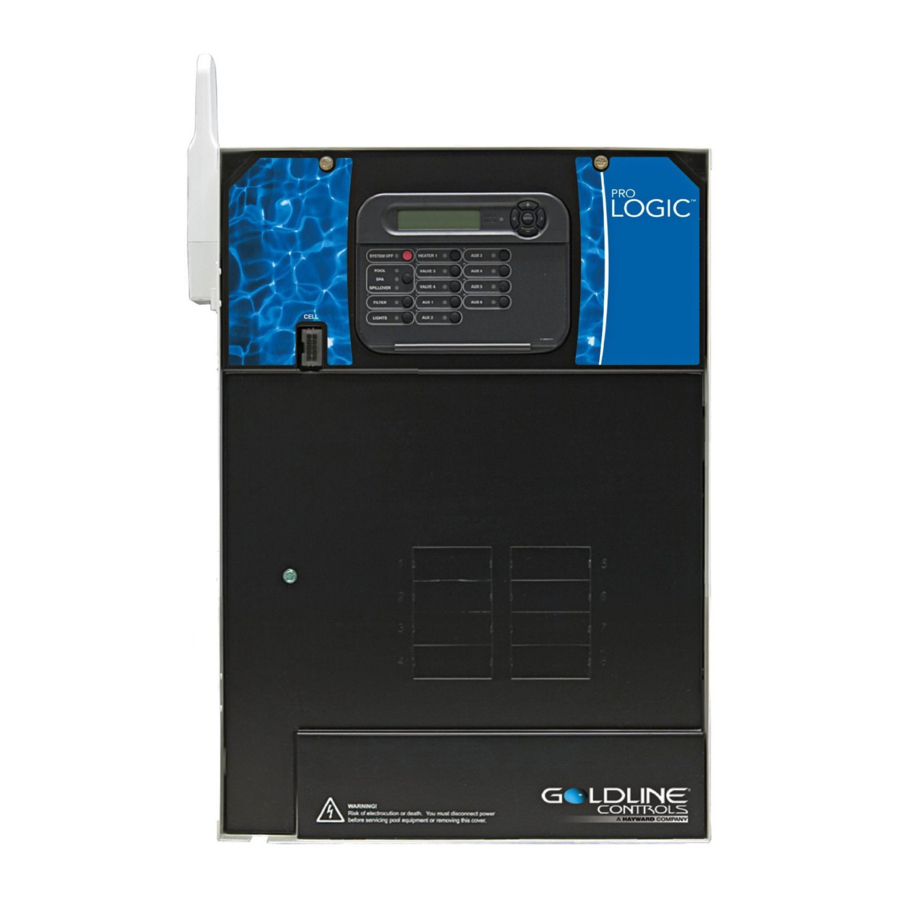
ProLogic: How It Works • All ProLogic systems are salt chlorination ready and can control 4-16 high voltage relays, 3-4 valve actuators and 1-2 heaters. • These systems can manage: Hayward Variable Speed Pumps, ColorLogic Lighting, Sense & Dispense, AquaConnect Homenet, as well as a wide variety of remotes. -
Page 5: How To
ProLogic® How To:... -
Page 6: Reset Average Salt & Adjust Chlorinator Output
How To: Reset Average Salt Follow these steps ONLY if Salt Chlorination is Enabled. The Average Salt level needs to be reset after initial start up, after a board replacement, following major pool chemistry adjustments, and when a cell is replaced. Step 1 Step 2 The active salt readings (instant salt) appears in the ‘Diagnostic... - Page 7 How To: Adjust Chlorinator Output Follow these steps to adjust the Chlorinator Output Percentage ONLY if Salt Chlorination is Enabled. NOTE: IF Sense & Dispense ‘ORP Auto Sensing’ is being used, output must be adjusted under the ‘Chemistry Config. Wizard’; refer to next page. Step 1 Step 2 To display the settings, press the ‘Menu’...
-
Page 8: Adjust Orp Set Points & Adjust Heater Set Points
How To: Adjust ORP Set Point (S&D) Follow these steps to adjust the Chlorinator’s ORP Set Point, ONLY if Salt Chlorination is Enabled AND the system is configured for ‘ORP Auto Sensing’. Step 1 Step 2 Press the ‘Menu’ until, ‘Configuration Menu-Locked’ appears. To Press the (>) repeatedly, until ‘Chemistry Config. - Page 9 ‘MENU’ button four times to return to the ‘Default Menu’. NOTE: If the heater is not wired through the ProLogic then it will need to be adjusted directly on the Heater instead of through the ProLogic system.
-
Page 10: Clear Inspect Cell Message & Set A Pump Schedule
How To: Clear Inspect Cell Message Follow these steps ONLY if Salt Chlorination is Enabled AND the system shows a Check System LED, with an ‘Inspect Cell’ message. Every 500 operational hours this message will appear. Before resetting, inspect and/or clean the cell if necessary. Step 1 Step 2 Press the ‘Menu’... - Page 11 How To: Set a Pump Schedule Follow these steps to program your pump to turn ON & OFF automatically through the Timer’s Menu. Step 1 Step 2 Press the ‘Menu’ repeatedly, until ‘Timers Menu’ appears on the Press the (>) until ‘Filter T1,T2,T3,T4’ or ‘Spa-all’ appears on the display.
-
Page 12: Change Vsp Speed Settings & Clean The Turbo Cell
How To: Change VSP Speed Settings Follow these steps ONLY if using a Variable Speed Pump in conjunction with the ProLogic Controller AND you wish to change the pump’s operational percentages. Step 1 Step 2 Press the ‘Menu’ repeatedly, until ‘Settings Menu’ appears on Press the (>) until ‘VSP Speed Settings’... - Page 13 Even if a TurboCell appears clean, it may still equipment. It is highly recommended to use a require cleaning if salt accuracy is off AND/OR chlorine Hayward Cell Cleaning Stand as shown on the right production has diminished. (GLX-CELLSTAND) NOTE: ALWAYS WEAR PROPER EYE PROTECTION AND PROTECTIVE GLOVES.
- Page 14 How To: Clean the TurboCell (cont.) The TurboCell draws amperage when power is applied, during chlorination. The amperage draw will be impaired when calcium and other debris exist within the cell’s electrolytic grid; this in turn effects the salt reading and chlorination efficiency. Mix: 4 Parts H O / 1 Part Muriatic Acid Carefully Pour Solution into Cell...
- Page 15 How To: Clean the TurboCell (cont.) The check system > ‘Inspect Cell’ message indicates that the system is recommending the TurboCell should be inspected and cleaned (if necessary). This message will appear every 500 operational hours as a reminder to inspect and/or clean the TurboCell. Thoroughly Rinse Cell &...
-
Page 16: Troubleshooting
ProLogic® Troubleshooting... -
Page 17: No Cell Power/Low Volts
STOP: This must be resolved by a certified technician. Please contact tech service: (908) 355-7995 OR contact a pool professional: https://www.hayward-pool.com/shop/en/pools/Dealer-Locator NOTE: These reported errors DO NOT indicate that there is a problem with the turbo cell. However, it is recommended to clean the cell, if it is calcified, before scheduling service repairs. Cell cleaning... -
Page 18: Chlorinator Off, High Salt/Amps
2. Chlorinator OFF, High Salt/Amps The message ‘Chlorinator Off – High Salt/Amps’ indicates that the ProLogic has detected an amperage draw, from the turbo cell, that exceeds the allowable threshold for the programmed cell model. Test salt level Reset chlorinator in diagnostics... - Page 19 Verify chlorinator readings Step 2C After a short delay, new readings should appear on the display. These readings report on the active chlorinator circuit. IF the ProLogic is reporting a voltage of 35V or higher, contact a contact a pool professional: https://www.hayward-pool.com/shop/en/pools/Dealer-Locator IF voltage is under 35V, Contact tech service: (908) 355-7995 for more assistance.
-
Page 20: Chlorinator Off, High Salt/Amps
2. Chlorinator OFF, High Salt/Amps (cont.) The salt concentration will need to reduced. To calculate how much water to drain, follow the formula provided below (Proportional Method): Step 2D Part I Part 1: Take the average depth of the pool in inches and multiply that by 3200. -
Page 21: Chlorinator Off, Cell Sensor Open
6). Press the ‘Menu’ button until the contact an authorized dealer to purchase a ‘Default Menu’ appears then scroll to the right. IF the replacement: https://www.hayward- error message has not cleared, contact technical pool.com/shop/en/pools/Dealer-Locator support for more assistance: (908) 355-7995. -
Page 22: Freeze Protection Active: In Error
4. Freeze Protection Active: In Error Freeze Protection is a safety feature built into ProLogic systems to protect all freeze enabled equipment from dangerously low temperatures. Verify ambient temperature Locate & inspect air sensor Step 4A Step 4B Freeze Protection will run between a range of 33ºF - Navigate through the ‘Default Menu’, press the (>) until... -
Page 23: Freeze Protection Active: In Error
4. Freeze Protection Active: In Error (cont.) When freeze protection is active, even though the water temperature is reading normal, the ProLogic will continue to make chlorine. Suspending freeze protection by activating service mode will suspend chlorination. Contact service (*optional: activate service mode) Step 4C The air temperature sensor may need to be replaced. -
Page 24: Heater Not Firing
5. Heater Not Firing The ProLogic features a normally open circuit for each heater. When heat is called for, based on the temp set point and water sensor, the low voltage contact will close; once closed, the low voltage supplied by the heater should be returned to it. - Page 25 5. Heater Not Firing (cont.) Service mode cancels all scheduled automation and also suspends safety features such as ‘Freeze Protection’. If the heater only fires while in service mode, make sure freeze protection is not active, also verify that solar priority is not overriding regular heating. Service mode test Inspect heater display Step 5C...
- Page 26 5. Heater Not Firing (cont.) The ProLogic supports features like Solar Priority. Verify that no additional heating is occurring, as this can take precedence over automatic heating. Verify set points and/or errors Step 5E First verify the status of the Check System LED. IF ON, go to the ‘Default Menu’...
-
Page 27: Auxiliary Equipment Inactive
6. Auxiliary Equipment Inactive The ProLogic should only attempt to turn on wired equipment if the LED next to the specific auxiliary or valve is illuminated. Inspect relay LED Service mode Step 6A Step 6B The ProLogic will only attempt to engage a relay if the Activate service mode &... - Page 28 6. Auxiliary Equipment Inactive (cont.) Service mode suspends all automation, including schedules, equipment protections and set point limitations. Equipment running/on in service? Step 6C While in service mode: IF the equipment wired to the relay in question does not run/turn on, then there is likely a problem with that piece of equipment.
-
Page 29: Wireless Remote Not Pairing To Prologic
7. Wireless Remotes Not Pairing to ProLogic All Wireless remotes that pair with the ProLogic run of RF. There are up to 5 RF channels that can be used to counteract possible interference. Check for antenna Service mode Step 7A... - Page 30 7. Wireless Remotes Not Pairing to ProLogic The ProLogic RF remotes should work between 200-400ft line of sight (depending on the remote). The RF antenna may also be mounted up to 500ft away from the ProLogic control panel. Check for RF settings...
-
Page 31: Wireless Remote Not Pairing To Prologic
7. Wireless Remotes Not Pairing to ProLogic All Wireless remotes that pair with the ProLogic run of RF. There are up to 5 RF channels that can be used to counteract possible interference. Change wireless channel Verify compatibility Step 7E... -
Page 32: Pump Error Codes & 9. Sense & Dispense Error Codes
8. Pump Error Codes Below is a list of additional “Check System” error codes which relate to the ProLogic’s operation with Hayward’s TriStar and EcoStar Variable Speed Pumps. All errors may be prefaced with Pool Filter (or Spa Filter (Dual Equipment) or Lights or Aux 1…14): •... - Page 33 9. Sense & Dispense Error Codes Below is a list of additional “Check System” error codes which relate to the Pro Logic’s operation with Sense and Dispense™ Chemistry Automation: • pH Calibration Error • ORP Low-Check Chlor •pH Probe Error •ORP High-Check Chlor •pH Low-Check feeder •ORP High-Chlor off...
-
Page 34: Additional Sensor Error Codes
•Pool Sensor Short •Chk Flow Switch ‘Open sensor’, ‘Cell Missing’, and ‘Check Flow Switch’ errors should be checked by confirming sensor wiring is not broken. Shorted sensor errors require may require replacement by a pool professional, to locate one, please visit: https://www.hayward-pool.com/shop/en/pools/Dealer-Locator... -
Page 35: Additional Information
ProLogic® Additional Information... -
Page 36: Cell Compatibility Chart & Salt Addition Chart
Software Revision: Cell Compatibility Chart Cell Compatibility Chart Control Center Model Cell Type AquaLogic AquaPlus ProLogic T-CELL-3 For residential pools up to 15,000 4.10 or later 4.10 or later gallons T-CELL-5 For residential pools up to 18,000 All revisions All revisions... - Page 37 Salt Addition Chart: lbs. required for 3200ppm Pool Size - Gallons Current Salt Level 8,000 10,000 12,000 14,000 16,000 18,000 20,000 22,000 24,000 26,000 28,000 30,000 32,000 34,000 36,000 38,000 40,000 1013 1067 1000 1000 1200 1400 1600 1800 2000 2200 2400 2600...
-
Page 38: Salt Addition Chart & Chlorine Output
Chlorine Output & Salt Levels 1. The cycle time (reversal of polarity) is 180 minutes (3 hrs). When you set the ‘Desired Output %’ through the control system it sets the level of chlorination based on the three hour cycle. 50% represents the factory default. The following represents an example of how the system reacts to percentage output: •... - Page 39 Chlorine Output & Salt Levels (cont.) 3. It is possible that the displayed salt level can be significantly different from the actual salt level (when measured through an independent test). This can happen as a result of a dirty cell or from a cell that is experiencing the aging process. Low salt readings should ALWAYS be followed by a cell cleaning first and then an actual meter measurement of the salt level in the water.
Need help?
Do you have a question about the ProLogic and is the answer not in the manual?
Questions and answers
I'm getting an vsp error 80 code
I got a 76p code on salt meter - never saw before. What does it mean? Pool is green