Hayward Pro Logic Installation Manual
Automation and chlorination
Hide thumbs
Also See for Pro Logic:
- Operation manual (52 pages) ,
- Installation manual (48 pages) ,
- Installation and operation manual (13 pages)
Table of Contents
Advertisement
Quick Links
Programming Menu
default menu
Flowchart
settings menu
maintenance menu
timers menu
PS-4 only
diagnostic menu
configuration menu
PS-4 only
620 Division St.
Elizabeth, NJ 07207
day and time
water temperature
air temperature
denotes conditional items
chlorinator setting
salt level
reason pump is running (not scheduled)
inspect cell
reason hi-speed is running (not scheduled)
countdown time remaining
heater control status
system manual off
check system error
group active
filter vsp speed/reason
spa filter vsp speed/reason
lights/aux speed/reason
pH/ORP levels
spa heater1 temperature
pool heater1 temperature
spa heater2 temperature
pool heater2 temperature
spa heater2 priority
pool heater2 priority
spa solar temperature
pool solar temperature
vsp speed settings
superchlorinate
spa chlorinator setting
pool chlorinator setting
aux colorlogic settings
day and time
backlit display light
beeper
teach wireless remote
wireless channel
pH calibration wizard
clean probe wizard
pool filter 1 or hi-speed 1
pool filter 2 or lo-speed 1
pool filter 3 or hi-speed 2
pool filter 4 or lo-speed 2
spa filter 1 or hi-speed
spa filter 2 or lo-speed
spa
lights
aux1
aux2
valve3
valve4
superchlorinate
chlorinator diagnostics
instant salt
pH/orp levels
flow switch
cell temperature sensor
water/pool sensor
spa sensor
air sensor
solar sensor
vsp speed/power
main software revision
display software revision
expansion unit software revision
chemistry sense module software
vsp software revision
RF base software revision
6 button spa side software revision
digital spa side software revision
colorlogic module software revision
colorlogic light software revision
chlorinator
chemistry config. Wizard
pool/spa
filter
spa filter
heater1
heater2
solar
colorlogic
external input active state
lights
aux1
aux2
valve3
valve4
6 button spa side remote
digital spa side remote
remote menus
7-day or weekend/weekday timeclock
12 hour or 24 hour time format
ºF or ºC
vsp speed (% or rpm)
reset colorlogic to default
reset to default
Copyright © 2010 Hayward
092330D RevG
Pro Logic
Automation and Chlorination
Installation Manual
for models
PL-PS-4
PL-PS-8-V
PL-PS-8
PL-PS-16-V
PL-PS-16
www.haywardnet.com
Advertisement
Table of Contents

Subscribe to Our Youtube Channel
Related Manuals for Hayward Pro Logic


Summary of Contents for Hayward Pro Logic
- Page 1 7-day or weekend/weekday timeclock 12 hour or 24 hour time format ºF or ºC vsp speed (% or rpm) reset colorlogic to default 620 Division St. 092330D RevG reset to default www.haywardnet.com Copyright © 2010 Hayward Elizabeth, NJ 07207...
-
Page 2: Important Safety Instructions
(3) years. Hayward/Goldline also warrants its Aqua Trol chlorination products to be free of defects in materials and work- manship, under normal use and service for a period of one (1) year. These warranties are applicable from the initial date of installation on private residential swimming pools in the US and Canada. -
Page 3: Table Of Contents
Before You Begin..............Installation Steps..............1. Preparing General Water Chemistry............. Pool/Spa Water Salt..................2. Mounting Pro Logic Control Center........... Equipment PS-16 Expansion Unit............Temperature Sensors............Optional Chlorination Function..........Optional AQL-CHEM ORP and pH Sensing Kit....Optional AQL-COLOR-MODHV Network Module..... Optional Wired Remote Display/Keypad...... -
Page 4: Introduction Before You Begin
The pump will automatically turn off at the end of the 5 minute heater cooldown period. Before You Begin For more detailed instructions on control and operation of the Pro Logic system, refer to the Operation Manual. What’s Included Before attempting to install the Pro Logic system, check that the following components have been included in the... -
Page 5: Installation Steps
Follow these instructions to verify that the Pro Logic is properly controlling the heater. 4. Electrical Wiring (page 12) 1. Check that the Pro Logic is calling for the heater to turn on as indicated by the “Heater” LED being illuminated. Main service If the “Heater”... -
Page 6: General Water Chemistry
Move to previous/next configuration menu Salt is required only if you are using the chlorinator features on the Pro Logic Control. If you are NOT using the This is the unit of measure for displaying the speed of the variable speed pump. Select % of maximum chlorinator, it is recommended that you follow all of the other chemistry recommendations besides salt. - Page 7 Select Digital Spa result in low chlorine production. A high salt level can cause the Pro Logic to stop chlorinating. The salt in your This menu only appears if more than one AQL-SS-D is detected at power up. Select which of the pool/spa is constantly recycled and the loss of salt throughout the swimming season should be minimal.
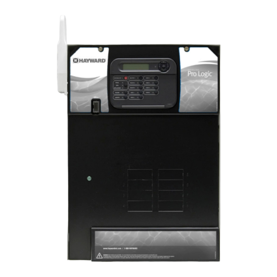
- Page 8 Select 6B Spa The Pro Logic is contained in a raintight enclosure that is suitable for outdoor mounting. The control must be This menu only appears if more than one AQL-SS-6B is detected at power up. Select which of the mounted a minimum of 5 ft.
-
Page 9: Temperature Sensors
+ to view/change Move to previous/next configuration menu Temperature Sensors Three sensors are included with the Pro Logic. A water sensor and an air sensor must be installed at all times for Valve3 Name Rotates between all available names proper operation. An additional supplied sensor can be used for either solar or dual equipment function. If both... -
Page 10: Optional Base Station
Freeze Protection is not available for low speed filter pump, dimmer, wireless remotes and the base station on the Pro Logic main control unit is 400 feet (120m) line of sight or 200 feet group, super chlorinate or pH dispense functions. -
Page 11: Standard" Pool/Spa Configuration
CHECK VALVE HEAT VALVE HEATER POOL/SPA SUCTION Low Speed of a 2-Speed Spa Filter Pump – the Pro Logic will turn on the aux relay whenever the low PUMP VALVE FILTER SOLAR FLOW speed operation of the Dual Equipment Spa filter pump is required. “Pool and Spa-Dual” (located in... - Page 12 3. The dual equipment spa sensor should be installed on the spa loop prior to the heater and will display the program the timeclocks. A sheet of small name labels is included with the Pro Logic main unit and each spa temperature whenever the “Spa Filter”...
-
Page 13: Dual Equipment" Pool/Spa - Shared Heaters
7. The plumbing diagram on page 9 is intended to be used as a general guideline and is not a complete Low Speed of a 2-Speed Spa Filter Pump – the Pro Logic will turn on the lights relay whenever the low plumbing schematic for the pool. -
Page 14: Turbo Cell
Pro Logic much more user friendly to the homeowner when they want to turn various Flow Switch lights on or off. A sheet of small name labels is included with the Pro Logic main unit and each remote (supplied with P-KIT) display/keypad so that the “Lights”... -
Page 15: Main Service
External Input to “Active Closed”. Connect a ground wire from the primary electrical panel to the Pro Logic ground bus bar. Also ground each piece of high voltage (120 or 240VAC) equipment that is connected to the Pro Logic control relays or circuit breakers. -
Page 16: Pro Logic Control Power
High Voltage (120/240V) Pool Equipment Toggle between Enabled and Disabled (default) Solar Solar All Pro Logic relays are double pole (they make/break both “legs” of 240V circuits) and are rated at 3HP/30A at Disabled Move to next menu item or previous/next configuration menu 240V (1½HP/30A at 120V). - Page 17 VSP pump control and be on when the output is on. When the output is off, the relay will be off. Note that when the relay is off (power off to the VSP), the Pro Logic will not display errors or diagnostics Heater1 for the pump.
-
Page 18: Low Voltage Wiring
Move to next menu item External Input Toggle between Enabled and Disabled (default) The Pro Logic provides a set of low voltage dry contacts that can be connected to most gas heaters or heat pumps Disabled Move to previous/next configuration menu with 24V control circuits. - Page 19 This feature will help protect the filter pump from damage due to no flow. When used with a Hayward flow switch, the Pro Logic monitors the state of water flow when the filter pump is on. If no flow is detected for more than 15 minutes, the Pro Logic will shut down the pool pump and the “Check...
- Page 20 Filter Name The Pro Logic allows you to assign any one of a number of names (e.g. “Filter Pump, Pool Filter, Spa Filter, etc.) to the filter relay. This will make the Pro Logic more user friendly to the homeowner when...
- Page 21 Requires use of the optional AQL-CHEM Sensing Kit. Following the steps of the Chemistry Config. Wizard will set up the AQL-CHEM to sense ORP and pH levels and, if the chlorination function is used, can configure the Pro Logic to generate the correct amount of chlorine to properly sanitize the Fireman’s pool.
- Page 22 Pro Logic will automatically chlorinate both the the Pro Logic main unit and the wired remote display/keypad are numbered: Connect 1 to 1, 2 to 2, etc. Refer to pool and spa according to the desired output setting (see Settings Menu in the Operation manual).
- Page 23 Note that all functions in the table may not be offered. The available functions are dependent on how the Pro Logic Base Station is configured. For example, if the Pro Logic is configured for a single heater, “Heater2” will not be available as an Plug in the connector from the wireless base station into the “Wireless”...
-
Page 24: Group Function
Refer to page 12 for the location of the connector. The latest version of the Pro Logic offers the ability to assign a Group function to a particular button. Instead of a button controlling one particular function, the button can be programmed to initiate a sequence of commands that External Input Interlock are programmed in the Configuration Menu.
Need help?
Do you have a question about the Pro Logic and is the answer not in the manual?
Questions and answers