Hayward Pro Logic Installation Manual
Automation and chlorination
Hide thumbs
Also See for Pro Logic:
- Operation manual (52 pages) ,
- Installation manual (48 pages) ,
- Installation and operation manual (13 pages)
Table of Contents
Advertisement
Pro Logic Programming Flow Chart
default menu
reason hi-speed is running (not scheduled)
settings menu
maintenance menu
timers menu
diagnostic menu
configuration menu
620 Division St.
Elizabeth, NJ 07207
day and time
denotes conditional items
water temperature
air temperature
chlorinator setting
salt level
reason pump is running (not scheduled)
inspect cell
countdown time remaining
heater control status
system manual off
check system error
filter vsp speed/reason
lights/aux speed/reason
pH/ORP levels
spa heater1 temperature
pool heater1 temperature
spa solar temperature
pool solar temperature
vsp speed settings
superchlorinate
spa chlorinator setting
pool chlorinator setting
day and time
backlit display light
beeper
teach wireless remote
wireless channel
pH calibration wizard
clean probe wizard
pool filter 1 or hi-speed 1
pool filter 2 or lo-speed 1
pool filter 3 or hi-speed 2
pool filter 4 or lo-speed 2
spa
lights
aux1
aux2
valve3
superchlorinate
chlorinator diagnostics
instant salt
pH/orp levels
flow switch
cell temperature sensor
water/pool sensor
air sensor
solar sensor
vsp speed/power
main software revision
display software revision
chemistry sense module software
vsp software revision
RF base software revision
6 button spa side software revision
chlorinator
chemistry config. Wizard
pool/spa
filter
heater1
solar
external input active state
lights
aux1
aux2
valve3
6 button spa side remote
remote menus
7-day or weekend/weekday timeclock
12 hour or 24 hour time format
ºF or ºC
vsp speed (% or rpm)
reset to default
Copyright © 2010 Hayward
092337C RevF
Pro Logic
Automation and Chlorination
Installation Manual
for model
PL-P-4
®
www.haywardnet.com
Advertisement
Table of Contents

Subscribe to Our Youtube Channel
Related Manuals for Hayward Pro Logic


Summary of Contents for Hayward Pro Logic
- Page 1 Pro Logic Programming Flow Chart default menu day and time denotes conditional items water temperature air temperature chlorinator setting salt level Pro Logic reason pump is running (not scheduled) ® inspect cell reason hi-speed is running (not scheduled) countdown time remaining...
-
Page 2: Important Safety Instructions
(3) years. Hayward/Goldline also warrants its Aqua Trol chlorination products to be free of defects in materials and work- manship, under normal use and service for a period of one (1) year. These warranties are applicable from the initial date of installation on private residential swimming pools in the US and Canada. -
Page 3: Table Of Contents
Table of Contents 1. Check that the Pro Logic is calling for the heater to turn on as indicated by the “Heater” LED being illuminated. If the “Heater” LED is illuminated, go directly to step 2; if not, then check the following: •... -
Page 4: Before You Begin
Before You Begin What’s Included Are you sure? Reset all configuration parameters Before attempting to install the Pro Logic system, check that the following components have been included in the + to proceed Move to previous/next menu (config. not reset) package: Config. -
Page 5: General Water Chemistry
(A, B or C) is to be configured. Salt is required only if you are using the chlorinator features on the Pro Logic Control. If you are NOT using the chlorinator, it is recommended that you follow all of the other chemistry recommendations besides salt. Refer to the 6B A, Button 1 description of the Pro Logic configuration menu for information on enabling/disabling the chlorinator (see page 20). -
Page 6: Salt
A low salt level will reduce the efficiency of the sanitization and result in low chlorine Settings Menu production. A high salt level can cause the Pro Logic to stop chlorinating. The salt in your pool/spa is constantly Move to previous/next configuration menu recycled and the loss of salt throughout the swimming season should be minimal. - Page 7 Liters Gallons Low Speed of a 2-speed Filter Pump – the Pro Logic will operate the aux relay whenever the low speed (pool size in meters) (pool size in feet) operation of the filter pump is required. It is very important that the “2-speed” filter pump option be...
-
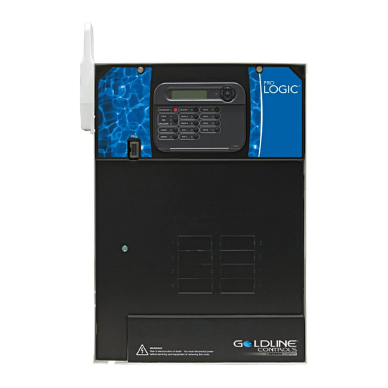
Page 8: Pro Logic Control Center
Lights Freeze Protection Three sensors are included with the Pro Logic. A water sensor and an air sensor must be installed at all times for This function helps protect equipment that is wired to the lights relay against freeze damage. If Freeze proper operation. -
Page 9: Optional Aql-Chem2 Co
When selecting a location, note or all functions except dimmer relay, super chlorinate that the wire to the Pro Logic main unit must be less than 500’ long. Refer to the remote’s installation instructions as well pH dispense, low speed, and group... -
Page 10: Optional Base Station
Note that the Pro Logic is compatible with AQL2 wireless remote controls only. A single AQL2-BASE-RF Base Move to previous/next configuration menu Station must be installed on the Pro Logic in order to use any of the Hayward wireless remote controls. With the Toggle between Enabled and Disabled (default) Solar Solar Base Station installed, there is no limit on the number of wireless remotes that can used. -
Page 11: Pool/Spa Configuration
This feature ensures that the heater cools down before water circulation is stopped. When enabled, the DRAIN ENERGY SUCTION NON-BOOST SAVER Pro Logic will continue to run the filter pump for 5 minutes after the heater turns off. During this period the PRESSURE CLEANER PRESSURE PRESSURE CLEANER... -
Page 12: Turbo Cell
Lowest Speed that ensures that water is flowing through the cell before the Pro Logic starts to generate chlorine. Failure to properly This is the lowest speed that the variable speed pump is allowed to run at. It is used as the lower limit in the install the flow switch can result in explosive gases accumulating in the pool plumbing system. -
Page 13: Main Service
The valves will remain in this position for the remainder of the super-chlorinate Connect a ground wire from the primary electrical panel to the Pro Logic ground bus bar. Also ground each piece of period. This option is usually preferable because both the pool and spa water will be filtered and sanitized. -
Page 14: General Purpose Outlet
Pro Logic will automatically detect and control any Aqua Rite(s) installed in the system. High Voltage (120/240V) Pool Equipment All Pro Logic relays are double pole (they make/break both “legs” of 240V circuits) and are rated at 3HP/30A at Display 240V (1½HP/30A at 120V). - Page 15 VSP pump control and be on when the output is on. When the output is off, the relay will be off. Note that when GREEN the relay is off (power off to the VSP), the Pro Logic will not display errors or diagnostics for the pump. The relay must YELLOW BLACK be on for diagnostic function.
-
Page 16: Low Voltage Wiring
Main PCB Heater Control The Pro Logic provides a set of low voltage dry contacts that can be connected to most gas heaters or heat pumps with Tighten nut 24V control circuits. Refer to the diagram below for a generic connection. The manuals supplied with most heaters also include specific wiring instructions for connecting the heater to an external control (usually identified as “2-wire”... - Page 17 Refer to the instructions in the heater manual for “2-wire Remote Thermostat” operation under “Remote Control Pro Logic main unit and the wired remote display/keypad are numbered: Connect 1 to 1, 2 to 2, etc. Refer to diagram Connections” and the diagram below: below.
- Page 18 3. Remove the jumper for the “fireman’s switch. 4. The wires to the Pro Logic must be separated from any line voltage wires. Failure to follow these instructions 4. Wire to the Pro Logic using wire rated for 105°C minimum.
Need help?
Do you have a question about the Pro Logic and is the answer not in the manual?
Questions and answers