
Subscribe to Our Youtube Channel
Related Manuals for Hayward ProLogic


Summary of Contents for Hayward ProLogic
- Page 1 ProLogic®/AquaLogic Troubleshooting Guide Residential TSG-PL447c Copyright 2016 Hayward Industries Inc.
- Page 2 Safety Precautions Warning High Voltage Electrocution Hazard Hazardous voltage can shock, burn, cause serious injury and or death. To reduce the risk of electrocution and or electric shock hazards: • Only qualified technicians should remove the dead front • Replace damaged wiring immediately •...
-
Page 3: Table Of Contents
Table of Contents How ProLogic® Works & Main PCB Layout Pg. 4-5 How To: Pg. 6-15 Reset Config. to Default & Reset Average Salt Adjust Chlorinator Output & Adjust ORP Set Point 9-10 Change Cell Type & Clear Inspect Cell Message... -
Page 4: How Prologic® Works & Main Pcb Layout
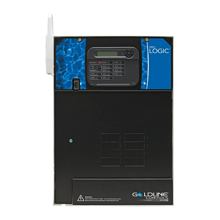
ProLogic: How It Works • All ProLogic systems are salt chlorination ready and can control 4-16 high voltage relays, 3-4 valve actuators and 1-2 heaters. • These systems can manage: Hayward Variable Speed Pumps, ColorLogic Lighting, Sense & Dispense, AquaConnect Homenet, as well as a wide variety of remotes. - Page 5 ProLogic: Main PCB Layout Transformer Rectifiers Remote DSP comm (RS485 – 10VDC) System Input Power (120VAC from breaker) Temp sensor terminal block (5VDC) Rectifier input (24VAC for Chlor. circuit) Air/Water Sensor Heater 1&2 terminal block (dry contacts) Transformer Output (24VAC) Valves 1-4 &...
-
Page 6: How To
ProLogic® How To:... -
Page 7: Reset Config. To Default & Reset Average Salt
How To: Reset Config. to Default Follow these steps ONLY if you wish to restore the system to factory default. WARNING: Resetting the system to factory default will wipe out all configuration changes, schedules, and settings preferences. Step 1 Step 2 Press the ‘Menu’... - Page 8 How To: Reset Average Salt Follow these steps ONLY if Salt Chlorination is Enabled. The Average Salt level needs to be reset after initial start up, after a board replacement, following major pool chemistry adjustments, and when a cell is replaced. Step 1 Step 2 The active salt readings (instant salt) appears in the ‘Diagnostic...
-
Page 9: Adjust Chlorinator Output & Adjust Orp Set Point
How To: Adjust Chlorinator Output Follow these steps to adjust the Chlorinator Output Percentage ONLY if Salt Chlorination is Enabled. NOTE: IF Sense & Dispense ‘ORP Auto Sensing’ is being used, output must be adjusted under the ‘Chemistry Config. Wizard’; refer to next page. Step 1 Step 2 To display the settings, press the ‘MENU’... - Page 10 How To: Adjust ORP Set Point (S&D) Follow these steps to adjust the Chlorinator’s ORP Set Point, ONLY if Salt Chlorination is Enabled AND the system is configured for ‘ORP Auto Sensing’. Step 1 Step 2 Press the ‘Menu’ until, ‘Configuration Menu-Locked’ appears. To Press the (>) repeatedly, until ‘Chemistry Config.
-
Page 11: Change Cell Type & Clear Inspect Cell Message
How To: Change Cell Type Follow these steps ONLY if Salt Chlorination is Enabled. It is important to verify which cell type is being used AND to verify the system is configured for the correct model. If incorrectly set, salt readings and chlorinator operations will be unreliable. Step 1 Step 2 Press the ‘Menu’... - Page 12 How To: Reset Inspect Cell Message Follow these steps ONLY if Salt Chlorination is Enabled AND the system shows a Check System LED, with an ‘Inspect Cell’ message. Every 500 operational hours this message will appear. Before resetting, inspect and/or clean the cell if necessary. Step 1 Step 2 Press the ‘Menu’...
-
Page 13: Clean The Turbo Cell
Even if a TurboCell appears clean, it may still equipment. It is highly recommended to use a require cleaning if salt accuracy is off AND/OR chlorine Hayward Cell Cleaning Stand as shown on the right production has diminished. (GLX-CELLSTAND) NOTE: ALWAYS WEAR PROPER EYE PROTECTION AND PROTECTIVE GLOVES. - Page 14 How To: Clean the TurboCell (cont.) The TurboCell draws amperage when power is applied, during chlorination. The amperage draw will be impaired when calcium and other debris exist within the cell’s electrolytic grid; this in turn effects the salt reading and chlorination efficiency. Mix: 4 Parts H O / 1 Part Muriatic Acid Carefully Pour Solution into Cell...
- Page 15 How To: Clean the TurboCell (cont.) The check system > ‘Inspect Cell’ message indicates that the system is recommending the TurboCell should be inspected and cleaned (if necessary). This message will appear every 500 operational hours as a reminder to inspect and/or clean the TurboCell. Thoroughly Rinse Cell &...
-
Page 16: Troubleshooting
ProLogic® Troubleshooting... -
Page 17: Prologic Vs. Aqualogic Skus
SKUs: ProLogic vs. AquaLogic Product SKUs ProLogic AquaLogic Main Board GLX-PCB-PRO Main Board GLX-PCB-MAIN **GLX-LOCAL-xx *GLX-PL-LOC-xx **substitute *substitute appropriate Local Display Local Display appropriate model model number (xx=P4, number (xx=P-4, PS-4, PS4, PS8, or PS16) PS-8, or PS-16) -
Page 18: No Cell Power/Low Volts
1. No Cell Power/Low Volts Verify 24VAC on No Cell Pwr. Check 20A Is 24VAC the transformer present? fuse /Low Volts output Verify Is fuse transformer damaged? input Is 120VAC available Replace fuse Replace main Replace Check Rectifier on both (GLX-F20A- board Transformer... - Page 19 1. No Cell Power/Low Volts ‘No Cell Power’ & Low Volts implies the chlorinator cycle has been interrupted due to no/low voltage detected when the cell power relay was turned on. If the system reports ‘CELL POWER ERROR’, replace the main board (see pg.
- Page 20 Inspect Fuse & Rectifier wiring Step 1C Step 1D Verify the ProLogic is receiving 120VAC between the Visually inspect & test the 20Amp fuse. IF fuse is blown, black & white wires on the “Control Power” side of the replace it (GLX-F20A-10PK). IF fuse is OK, inspect the terminal block.
- Page 21 2. Blank Display/No LEDs Problem is in Remove Local display cable Blank Display/ terminal block Is Display terminal blocks free of damage? normal? or comm NO LEDs and power cycle equipment. Contact tech Isolate System has a Power OFF & support for equipment to 2amp,...
- Page 22 2. Blank Display/No LEDs If the local display shows a blank display or no lights are illuminated an abrupt power outage may have been the cause, in this case, resetting the unit may correct this problem. Verify display connections Disconnect terminal blocks Step 2A Step 2B Turn off power at the main breaker and remove the...
-
Page 23: Blank Display
2. Blank Display/No LEDs (cont.) ProLogic main boards have a 2amp, permanently installed fuse that protects the local display circuit. AquaLogic main boards had a 3amp violet ATO style fuse that protected the local display circuit. Test fuse Test 3amp fuse... - Page 24 2. Blank Display/No LEDs (cont.) If the local display shows a blank display or no lights are illuminated an abrupt power outage may have been the cause, in this case, resetting the unit may correct this problem. Test incoming power Test local display power Step 2E Step 2F...
-
Page 25: Csm Comm Error
3. CSM Comm Error Is a chemistry Verify connections CSM Comm Wire is sensing module & inspect CSM damaged? Error installed? wire for damage Disable Problem Chemistry solved Sensing Replace CSM Test Comm port Module (GLX- power SD-ELEC-MOD) Replace CSM 5-10VDC Module (GLX-... - Page 26 3. CSM Comm Error CSM stands for (Chemistry Sensing Module), this error appears when Sense & Dispense is enabled, but the Chemistry Sensing Module is not found. Verify HL-CHEM is installed Disable sensing system Step 3A Step 3B HL-CHEM CSM = Chemical Sensing Module...
- Page 27 (GLX-SD-ELEC-MOD). IF free of damage, go to step 3D. chemistry sensing module (GLX-SD-ELEC-MOD). NOTE: If the cable that runs from the HL-CHEM to the ProLogic board is damaged then the chemistry module MUST be replace. DO NOT attempt to repair damaged cable.
-
Page 28: Chlorinator Off, High Salt/Amps
4. Chlorinator OFF, High Salt/Amps Reset Is salt level Test salt Chlor. Off 3400 or Chlorinator level High Salt/Amps below? diagnostics Dilute salt level Is voltage and reset reading above average salt 35V? Replace main Contact tech Verify correct board support TCELL type in (see pg. - Page 29 4. Chlorinator OFF, High Salt/Amps The message ‘Chlorinator Off – High Salt/Amps’ indicates that the ProLogic has detected an amperage draw, from the turbo cell, that exceeds the allowable threshold for the programmed cell model. Test salt level Reset chlorinator in diagnostics...
- Page 30 4. Chlorinator OFF, High Salt/Amps (cont.) The message ‘Chlorinator Off – High Salt/Amps’ indicates that the ProLogic has detected an amperage draw, from the turbo cell, that exceeds the allowable threshold for the programmed cell model. Verify chlorinator readings Verify cell programming...
- Page 31 4. Chlorinator OFF, High Salt/Amps (cont.) The salt concentration will need to reduced. To calculate how much water to drain, follow the formula provided below (Proportional Method): Step 4E Part I Part 1: Take the average depth of the pool in inches and multiply that by 3200.
-
Page 32: Comm Error 1 Or
5. Comm Error 1 OR 2 Power down Disconnect all Comm Error Comm Error control for at terminal blocks and 1 or 2 still present? least 2 minutes comm equipment Did Comm Problem Error clear? solved Problem is in Test local terminal block display wiring or comm... - Page 33 IF still present, go to 5C. NOTE: With ProLogic revision 4.10, a heater terminal block was added (moving the heaters off the main sensor block which was common in older revisions). Verify all connected heaters are wired to...
- Page 34 5. Comm Error 1 OR 2 (cont.) Comm Error 2: Typically appears when power is incorrectly applied to the communication circuit, a problem with the local display, OR in some rare cases the main circuit board. Test the local display harness Replace the local display Step 5C Step 5D...
-
Page 35: Heater Not Firing
6. Heater Not Firing Test both heater Is main Heater Not Is Heater LED term. blocks to circulation Firing ground for pump running? 12-24VAC Go to section 7 Put the system The problem Turn ON Pump, Both term. and test pump in service resides on the Is pump ON? - Page 36 6. Heater Not Firing The ProLogic features a normally open circuit for each heater. When heat is called for, based on the temp set point and water sensor, the low voltage contact will close; once closed, the low voltage supplied by the heater (12-24VAC) should be returned to it.
- Page 37 6. Heater Not Firing (cont.) Service mode cancels all scheduled automation and also suspends safety features such as ‘Freeze Protection’. If the heater only fires while in service mode, make sure freeze protection is not active, also verify that solar priority is not overriding regular heating. Service mode test Test the heater relay Step 6C...
- Page 38 6. Heater Not Firing (cont.) The ProLogic supports features like Solar Priority. Verify that no additional heating is occurring, as this can take precedence over automatic heating. Troubleshoot heater Verify set points and/or errors Step 6E Step 6F Verify the heater has power AND inspect heater for First verify the status of the Check System LED.
-
Page 39: Auxilariry Not Running
7. Auxiliary Equipment Inactive Inspect display, Verify 20-25VDC AUX Equip. verify the AUX on low voltage Section B Inactive LED is ON side of relay Relay line Is LED Is voltage power present? illuminated? present? (120/240VAC) Correct Put the system in Replace main Is AUX plugged service mode &... - Page 40 7. Auxiliary Equipment Inactive The ProLogic Relays are rated for 120/240VAC, 300W, 25A. To avoid damage, make sure wired equipment does not exceed these specifications. Inspect relay LED Service mode Step 7A Step 7B The ProLogic will only attempt to engage a relay if the Activate service mode &...
- Page 41 7. Auxiliary Equipment Inactive (cont.) Service mode suspends all automation, including schedules, equipment protections and set point limitations. Equipment running/on in service? Test relay: low voltage side Step 7C Step 7D While in service mode: IF the equipment wired to the With the Auxilary LED illuminated, remove the relay relay in question does not run/turn on, go to step 7D.
- Page 42 7. Auxiliary Equipment Inactive (cont.) There are two relay sockets on the ProLogic board. IF the ProLogic is a P-4, PS-4, OR PS-8V then the top socket should be filled and the bottom should remain open. Inspect Relay wiring harness...
- Page 43 7. Auxiliary Equipment Inactive (cont.) Test relay: high voltage (load side) Step 7G With the Auxiliary LED illuminated, test the load side of the relay off the second terminal to ground (left to right) for 120VAC. For 240V equipment, also test the fourth terminal to ground for 120VAC. IF no voltage is present on either 2 OR 2 AND 4, then replace the relay (GLX-RELAY).
-
Page 44: Additional Information
ProLogic® Additional Information... -
Page 45: Cell Compatibility Chart & Air Sensor Chart
Software Revision: Cell Compatibility Chart Cell Compatibility Chart Control Center Model Cell Type AquaLogic AquaPlus ProLogic T-CELL-3 For residential pools up to 15,000 4.10 or later 4.10 or later gallons T-CELL-5 For residential pools up to 18,000 All revisions All revisions... - Page 46 Air/Water Sensors: Resistance Chart Use the following chart to determine the reported temperature of a sensor based on either resistance (with sensor disconnected) or DC voltage (with sensor connected): F° Ohms Volts F° Ohms Volts F° Ohms Volts F° Ohms Volts F°...
-
Page 47: Salt Addition Chart & Chlorine Output
Salt Addition Chart: lbs. required for 3200ppm Pool Size - Gallons Current Salt Level 8,000 10,000 12,000 14,000 16,000 18,000 20,000 22,000 24,000 26,000 28,000 30,000 32,000 34,000 36,000 38,000 40,000 1013 1067 1000 1000 1200 1400 1600 1800 2000 2200 2400 2600... - Page 48 Chlorine Output & Salt Levels 1. The cycle time (reversal of polarity) is 180 minutes (3 hrs). When you set the ‘Desired Output %’ through the control system it sets the level of chlorination based on the three hour cycle. 50% represents the factory default. The following represents an example of how the system reacts to percentage output: •...
- Page 49 Chlorine Output & Salt Levels (cont.) 3. It is possible that the displayed salt level can be significantly different from the actual salt level (when measured through an independent test). This can happen as a result of a dirty cell or from a cell that is experiencing the aging process. Low salt readings should ALWAYS be followed by a cell cleaning first and then an actual meter measurement of the salt level in the water.
-
Page 50: Reading Serial Numbers
Reading Serial Numbers Beginning 08-05-2011 3L11284 Standard Warranty Term 3L11284 Product Family 3L11284- 123456 3L11284 Year of Manufacture 3L11284 Day of Manufacture 123456 = Manufacturing ID Beginning 11-01-2001 3L0112 = Standard Warranty Term 3L0112 = Product Family 3L0112- 123456 3L0112 = Year of Manufacture 3L0112 Month of Manufacture...
Need help?
Do you have a question about the ProLogic and is the answer not in the manual?
Questions and answers