Table of Contents
Advertisement
Quick Links
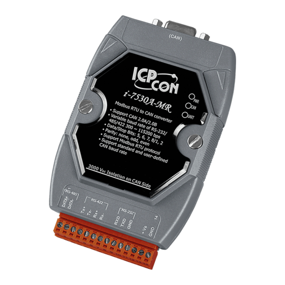
The I-7530A-MR Modbus RTU to CAN
Warranty
All products manufactured by ICP DAS are under warranty regarding
defective materials for a period of one year from the date of delivery to the
original purchaser.
Warning
ICP DAS assumes no liability for damages resulting from the use of this
product. ICP DAS reserves the right to change this manual at any time without
notice. The information furnished by ICP DAS is believed to be accurate and
reliable. However, no responsibility is assumed by ICP DAS for its use, or for
any infringements of patents or other rights of third parties resulting from its use.
Copyright
Copyright 2016 by ICP DAS. All rights are reserved.
Trademark
The names used for identification only may be registered trademarks of
their respective companies.
I-7530A-MR Modbus RTU to CAN Converter User's Manual (Version 1.07, 06/2016) ------------- 1
Converter
User's Manual
Advertisement
Table of Contents

Related Manuals for ICP DAS USA I-7530A-MR


Summary of Contents for ICP DAS USA I-7530A-MR
- Page 1 Copyright Copyright 2016 by ICP DAS. All rights are reserved. Trademark The names used for identification only may be registered trademarks of their respective companies. I-7530A-MR Modbus RTU to CAN Converter User’s Manual (Version 1.07, 06/2016) ------------- 1...
- Page 2 Testing the I-7530A-MR module ............... 43 3.5.1 Normal mode ..................... 45 3.5.2 Pair Connection Mode ................47 3.5.3 Modbus Slave Mode .................. 48 Command list (Only for normal mode) ................ 50 I-7530A-MR Modbus RTU to CAN Converter User’s Manual (Version 1.07, 06/2016) ------------- 2...
- Page 3 Modbus Read Configuration ..............92 6.3.1.1 Modbus Read Command..............93 6.3.1.2 Response CAN Message Configuration ......... 96 6.3.2 Modbus Write Configuration ..............99 6.3.3 Common Configuration ................103 Troubleshooting ......................106 I-7530A-MR Modbus RTU to CAN Converter User’s Manual (Version 1.07, 06/2016) ------------- 3...
-
Page 4: Introduction
“Normal”, “Modbus Slave” , “Pair connection”, and “Modbus Master” (firmware version v1.11 or later). In the Normal mode, the I-7530A-MR is designed to unleash the power of CAN bus via RS-232/485/422 communication method. It accurately converts ASCII format messages and CAN messages between RS- 232/485/422 and CAN networks. - Page 5 CAN devices on a CAN network. The following figure shows the application architecture in this mode. Figure 1-3: The application architecture in the Modbus Master mode. I-7530A-MR Modbus RTU to CAN Converter User’s Manual (Version 1.07, 06/2016) ------------- 5...
-
Page 6: Features
CAN message (Modbus Slave mode). Besides, function code 0x10 has additional functions for configuring module. Support Modbus Master function (firmware version v1.11 or later). I-7530A-MR Modbus RTU to CAN Converter User’s Manual (Version 1.07, 06/2016) ------------- 6... -
Page 7: Specifications
Storage temperature: -30 to 80ºC (-22 to 176ºF) Humidity: 10 to 95%, non-condensing LEDs: PWR LED for power CAN LED for CAN bus communication UART LED for UART communication I-7530A-MR Modbus RTU to CAN Converter User’s Manual (Version 1.07, 06/2016) ------------- 7... - Page 8 Function for transmitting or receiving CAN messages Application: Factory Automation Building Automation Home Automation Control system Monitor system Vehicle Automation I-7530A-MR Modbus RTU to CAN Converter User’s Manual (Version 1.07, 06/2016) ------------- 8...
-
Page 9: Hardware
2. Hardware Figure 2-1: Hardware profile of the I-7530A-MR I-7530A-MR Modbus RTU to CAN Converter User’s Manual (Version 1.07, 06/2016) ------------- 9... -
Page 10: Block Diagram
MR module. It provides the 3000V Isolation in the CAN and UART interface. And hardware media in RS-232 interface only adopts 3-wire connection. Figure 2-2: Block diagram of I-7530A-MR I-7530A-MR Modbus RTU to CAN Converter User’s Manual (Version 1.07, 06/2016) ------------- 10... -
Page 11: Pin Assignment
RS-422 TxD- RS-422 RxD+ RS-422 RxD- No use RS-232 RXD RS-232 TXD RS-232 GND No use +Vs(+10 ~ +30 VDC) Figure 2-3: Pin Assignment on the I-7530A-MR I-7530A-MR Modbus RTU to CAN Converter User’s Manual (Version 1.07, 06/2016) ------------- 11... -
Page 12: Hardware Connection
2.3.1 CAN port connection The pin assignment of the CAN port of the I-7530A-MR (DB9 male) is defined in both the CANopen DS102 profile and in appendix C of the DeviceNet specifications. It is the standard pin assignment for CAN interface. -
Page 13: Serial Port Connection
The following figures describe these port types and the wiring method for a serial device. Figure 2-5: RS-232 Wire Connection Figure 2-6: RS-422 Wire Connection Figure 2-7: RS-485 Wire Connection I-7530A-MR Modbus RTU to CAN Converter User’s Manual (Version 1.07, 06/2016) ------------- 13... -
Page 14: Terminator Resistor Settings
I-7530A-MR cover and use the JP3 to activate the 120 terminal resistor built in the module, as the Figure 2-9. Note that the default setting is active. Figure 2-9: Terminal Resistor Jumper I-7530A-MR Modbus RTU to CAN Converter User’s Manual (Version 1.07, 06/2016) ------------- 14... -
Page 15: Init / Normal Dip-Switch
Figure 2-10: Terminal resistor JP3 Jumper Position 2.5 Init / Normal Dip-switch On the back of the I-7530A-MR module, there is a DIP-switch used to configure the “firmware operation mode”, “firmware update mode” or “module configuration mode”. The following steps show how to use it. - Page 16 [2] Choose “COM” interface and “COM Port”. [2] Click “Browser” button to choose the firmware file. (e.g. I7530AMR_100.fw) [3] Click “Firmware Update” button to start firmware update process. I-7530A-MR Modbus RTU to CAN Converter User’s Manual (Version 1.07, 06/2016) ------------- 16...
-
Page 17: Firmware Operation Mode
LEDs are turned off. That means the I-7530A- MR module is working in the operation mode. In this mode, users can use the RS-232/485/422 device to send/receive CAN messages via COM port. I-7530A-MR Modbus RTU to CAN Converter User’s Manual (Version 1.07, 06/2016) ------------- 17... -
Page 18: Module Configuration Mode
The positions of these three LEDs are shown as Figure 2-17. (1) PWR LED : It is used to help users with checking if the I-7530A-MR is standby. If the module is supplied the proper power, the PWR LED is turned on. The different situations of the module may cause the different blinking display. - Page 19 CAN Bus Transmission Fail Blink every 100 ms PWR LED CAN Bus-Off Blink every 500 ms Power Failure Transmission Blink CAN LED Bus Idle Transmission Blink UART LED Bus Idle I-7530A-MR Modbus RTU to CAN Converter User’s Manual (Version 1.07, 06/2016) ------------- 19...
-
Page 20: Cable Selection
(heavier) the wire, the lower the number. For example: a 24AWG wire is thicker/heavier than a 26AWG wire. I-7530A-MR Modbus RTU to CAN Converter User’s Manual (Version 1.07, 06/2016) ------------- 20... -
Page 21: Software Utility
The next section will show you how to configure the I-7530A-MR and test it by using UART2CAN Utility. Figure 3-1: Configuration and testing screen for UART2CAN Utility. I-7530A-MR Modbus RTU to CAN Converter User’s Manual (Version 1.07, 06/2016) ------------- 21... -
Page 22: Install The Uart2Can Utility
Windows Installer 3.1: http://ftp.icpdas.com/pub/cd/fieldbus_cd/can/converter/i-7530a- mr/utility/windowsinstaller3_1/ .NET Framework 4 Client Profile: http://ftp.icpdas.com/pub/cd/fieldbus_cd/can/converter/i-7530a- mr/utility/dotnetfx40client/ Figure 3-2: Setup the Windows Installer and .NET Framework. I-7530A-MR Modbus RTU to CAN Converter User’s Manual (Version 1.07, 06/2016) ------------- 22... - Page 23 1. Click the “Next” button to continue. Figure 3-3: Setup the UART2CAN Utility. 2. Select the installation path of the UART2CAN Utility and click the “Next” button. Figure 3-4: Select Installation Folder. I-7530A-MR Modbus RTU to CAN Converter User’s Manual (Version 1.07, 06/2016) ------------- 23...
- Page 24 3. Confirm the installation. Click the “Next” button to start the installation. Figure 3-5: Confirm Installation. 4. Installation complete. Click the “Close” button to exit. Figure 3-6: Installation complete. I-7530A-MR Modbus RTU to CAN Converter User’s Manual (Version 1.07, 06/2016) ------------- 24...
-
Page 25: Configure The Module Parameters
3. Set the Init/Normal switch to the “Init” (Initial) position at least three seconds. 4. The PWR LED of the I-7530A-MR module will turned on and the other LEDs will flash approximately once per second. That means the I-7530A-MR module is working in the configuration mode. -
Page 26: Select The Communication Mode
RS-232/485/422 devices via CAN bus. In the Modbus Master mode, this module is worked as Modbus Master/CAN module. It can communicate with Modbus slave device via RS-232/485/422. I-7530A-MR Modbus RTU to CAN Converter User’s Manual (Version 1.07, 06/2016) ------------- 26... -
Page 27: Set The Com Port Parameters
CAN message commands are sent out from the COM port of I-7530A-MR. These three parameters above can only use at the “Normal” communication mode. Figure 3-10: The COM port of I-7530A-MR configuration. I-7530A-MR Modbus RTU to CAN Converter User’s Manual (Version 1.07, 06/2016) ------------- 27... -
Page 28: Set The Can Parameters
7530A-MR COM port will be transferred to the CAN bus directly. For more detail information about pair connection mode, please refer to the section 3.4. Figure 3-12: The configuration for Pair connection. I-7530A-MR Modbus RTU to CAN Converter User’s Manual (Version 1.07, 06/2016) ------------- 28... -
Page 29: Set The "Modbus Slave" Parameter
03/04/06/10 of Modbus RTU commands for reading and writing CAN messages. For more details about Modbus Slave mode, please refer to the section 5. Figure 3-13: The configuration for Modbus Slave mode. I-7530A-MR Modbus RTU to CAN Converter User’s Manual (Version 1.07, 06/2016) ------------- 29... -
Page 30: Configuration Of Default Value
3.2.7 Configuration of default value If users click the “Defaults” button, all of the module communication parameters on the I-7530A-MR will be set to the factory default, which are: Communication Mode = Normal RS232/485/422: Baud rate = 115200 kbps Data Bit... -
Page 31: Load/Save The Parameter Configuration
(*.INI). And the “Save Parameter from Utility” function provides users to save the current configuration to a file (*.INI). Figure 3-14: Load/Save the parameter configuration from/to file. I-7530A-MR Modbus RTU to CAN Converter User’s Manual (Version 1.07, 06/2016) ------------- 31... -
Page 32: Can Filter Configuration
When users set the CAN filter first time, they need use “Download CAN Filter” field. Step 1: Click the “Create CAN Filter File” button to start setting CAN filter. Then uses will see the following window. I-7530A-MR Modbus RTU to CAN Converter User’s Manual (Version 1.07, 06/2016) ------------- 32... - Page 33 CAN ID in the list will be received and other CAN IDs which are not in list will be dropped. Add single CAN ID filter Start Add a range of CAN ID filter Figure 3-17 Add single or group CAN filter I-7530A-MR Modbus RTU to CAN Converter User’s Manual (Version 1.07, 06/2016) ------------- 33...
- Page 34 The “No.” field means that the sequential number of the CAN filter setting. The “CAN Port” field means that the filter setting is belong to which CAN port. In the I-7530A-MR module, users don’t need to care about this field. The “Accepted IDs” field means that which CAN ID can be passed.
-
Page 35: Download A Existed Can Filter File
Download a existed CAN Filter file Click “Download CAN Filter File” to download the selected CAN filter file into the I-7530A-MR module. Figure 3-20 Download CAN filter data I-7530A-MR Modbus RTU to CAN Converter User’s Manual (Version 1.07, 06/2016) ------------- 35... -
Page 36: Read I-7530A-Mr Can Filter Configuration
Click the “Read from Module” item on the Utility tool bar to read CAN filter setting from the I-7530A-MR module and save the CAN filter setting as a file (*.FLT). Figure 3-21 Read CAN filter form the I-7530A-MR module I-7530A-MR Modbus RTU to CAN Converter User’s Manual (Version 1.07, 06/2016) ------------- 36... -
Page 37: Pair-Connection Mode Description
I-7530A-MR#1 Configuration I-7530A-MR#2 configuration Communication Descriptions: If there are 7 bytes data, “1234567”, transmitted from Device1, the Device2 will also receive “1234567” from the COM port of I-7530A-MR#2. I-7530A-MR Modbus RTU to CAN Converter User’s Manual (Version 1.07, 06/2016) ------------- 37... - Page 38 CAN 2.0B is used, the CAN ID is 29-bit ID. Here, assume users set the Fixed Tx CAN ID field of I-7530A-MR#1 to be 0x001 ( “0x” is for hexadecimal format) and CAN 2.0A is used, the CAN ID displayed in above figure is 0x001.
- Page 39 “12345678” immediately, and receive the data “9” with a little delay. But, Device2 in application 2 will receive the data “123456789” at the same time (Max. 256 bytes data at the same time). I-7530A-MR Modbus RTU to CAN Converter User’s Manual (Version 1.07, 06/2016) ------------- 39...
- Page 40 In order to apply this application, users need to configure the I-7530A- MR#1, I-7530A-MR#2, and I-7530A-MR#3 as follows. The RS-232 configurations of these I-7530A-MRs are decided by the connected RS- 232 device. Figure 3-25: I-7530A-MR#1 Configuration. I-7530A-MR Modbus RTU to CAN Converter User’s Manual (Version 1.07, 06/2016) ------------- 40...
- Page 41 “0021234567” because the Device1 is set to dynamic Tx CAN ID (Fixed Tx CAN ID is not checked). The first three bytes of “0021234567” is “002”, it means that the CAN ID is 0x002 while the I-7530A-MR#1 receives the RS-232 commands from the Device1 and transfers it to CAN message.
- Page 42 RS-232 commands come from. The general concept of transmitting data from Device1 to Device2 is shown below. Note: In pair connection mode, all command strings listed in the section 4 are useless. I-7530A-MR Modbus RTU to CAN Converter User’s Manual (Version 1.07, 06/2016) ------------- 42...
-
Page 43: Testing The I-7530A-Mr Module
3. Supply the 10~30 V power into the I-7530A-MR module through the power terminal. 4. The PWR LED on the I-7530A-MR module will be turned on and the other LEDs will be turned off. That means the I-7530A-MR is working in the operation mode. - Page 44 7530A-MR. There are the Normal mode, Pair connection mode and Modbus Slave mode. In the next section, we will describe how to use it. Figure 3-30: Select communication mode for the Utility. I-7530A-MR Modbus RTU to CAN Converter User’s Manual (Version 1.07, 06/2016) ------------- 44...
-
Page 45: Normal Mode
“Timer (ms)”, the Utility will transmit the message periodically. If the function “Add Checksum” is set to “Yes”, it means that messages sent to the I-7530A-MR by the Utility will be run with checksum mechanism. I-7530A-MR Modbus RTU to CAN Converter User’s Manual (Version 1.07, 06/2016) ------------- 45... - Page 46 MR_N_yyyyMMddmmss.txt” file. The indication of the file name is described as the figure below. Figure 3-33: The indication of the message log file name. I-7530A-MR Modbus RTU to CAN Converter User’s Manual (Version 1.07, 06/2016) ------------- 46...
-
Page 47: Pair Connection Mode
In addition, users can click the “Save” button to save the messages in the “Receive” text box into the “I-7530A- MR_P_yyyyMMddmmss.txt ” file. The indication of the file name is described below. I-7530A-MR Modbus RTU to CAN Converter User’s Manual (Version 1.07, 06/2016) ------------- 47... -
Page 48: Modbus Slave Mode
The second method (uncheck “Use Modbus RTU Command”) requires users to understand the Modbus RTU protocol. Then key-in the correct Modbus RTU command in the text box. Both of the methods I-7530A-MR Modbus RTU to CAN Converter User’s Manual (Version 1.07, 06/2016) ------------- 48... - Page 49 MR_M_yyyyMMddmmss.txt ” file. The indication of the file name is described below. Figure 3-37: The indication of the file name in the Modbus Slave mode. I-7530A-MR Modbus RTU to CAN Converter User’s Manual (Version 1.07, 06/2016) ------------- 49...
-
Page 50: Command List (Only For Normal Mode)
*Change the user-defined CAN baud rate P2BBBBB[CHK]<CR> configuration RA[CHK]<CR> Reboot the I-7530A-MR module. * NOTE: This command will write parameters into EEPROM and EEPROM is limited to 10,000,000 erase/write cycles. I-7530A-MR Modbus RTU to CAN Converter User’s Manual (Version 1.07, 06/2016) ------------- 50... - Page 51 1. Sum of the string = ‘R’ + ‘A’ = 52h + 41h = 93h. 2. Therefore the checksum is 93h and so [CHK]=”93”. 3. The command string with checksum =”RA93<CR>”. I-7530A-MR Modbus RTU to CAN Converter User’s Manual (Version 1.07, 06/2016) ------------- 51...
-
Page 52: Tiiildd...[Chk]
Note: It is necessary to enable the “Error Response” function while using the UART2CAN Utility in order to receive Syntax and/or communication error information. Example: Command: T2E88<CR> I-7530A-MR Modbus RTU to CAN Converter User’s Manual (Version 1.07, 06/2016) ------------- 52... -
Page 53: Eiiiiiiiildd...[Chk]
29 bits Identifier (00000000~1FFFFFFF) Data length (0~8) Response: Valid command: No response Invalid command: ?<Error Code><CR> Note: It is necessary to enable the “Error Response” function while using I-7530A-MR Modbus RTU to CAN Converter User’s Manual (Version 1.07, 06/2016) ------------- 53... -
Page 54: S[Chk]
Table 4-2: CAN baud rate list AsciiToHex(C) Description 10K baud rate of CAN 20K baud rate of CAN 50K baud rate of CAN 100K baud rate of CAN I-7530A-MR Modbus RTU to CAN Converter User’s Manual (Version 1.07, 06/2016) ------------- 54... -
Page 55: P0Bbdspcr[Chk]
CAN & RS232/485/422 FIFO= normal. 4.6 P0BBDSPCR[CHK]<CR> Description: Change the RS-232/485/422 configuration on the I-7530A-MR module and then reboot the I-7530A-MR module. Syntax: P0BBDSPCR[CHK]<CR> I-7530A-MR Modbus RTU to CAN Converter User’s Manual (Version 1.07, 06/2016) ------------- 55... - Page 56 Table 4-6: Other response list AsciiToHex(R) Description Bit 3 Reserved Bit 2 Reserved Bit 1 Enable timestamp response (0: No, 1: Yes) Bit 0 Enable error response (0: No, 1: Yes) I-7530A-MR Modbus RTU to CAN Converter User’s Manual (Version 1.07, 06/2016) ------------- 56...
- Page 57 Set the RS-232/485/422 baud rate=115.2 kbps, data bit=8, stop bit=1, none parity, no checksum, no error responses and no timestamp responses into the I-7530A-MR module and then reboot the I-7530A-MR module. I-7530A-MR Modbus RTU to CAN Converter User’s Manual (Version 1.07, 06/2016) ------------- 57...
-
Page 58: P1B [Chk]
UART2CAN Utility in order to receive Syntax and/or communication error information. Example: Command: P14<CR> Set the CAN baud rate=125 kbps into the I-7530A-MR module and then reboot the I-7530A-MR module. I-7530A-MR Modbus RTU to CAN Converter User’s Manual (Version 1.07, 06/2016) ------------- 58... -
Page 59: P2Bbbbb[Chk]
BBBBB is the hex format of the value14585 (83.333 x 1000). Example: Command: P214585<CR> Set the CAN baud rate=83.333 kbps into the I-7530A-MR module and then reboot the I-7530A-MR module. I-7530A-MR Modbus RTU to CAN Converter User’s Manual (Version 1.07, 06/2016) ------------- 59... -
Page 60: Ra[Chk]
UART2CAN Utility in order to receive Syntax and/or communication error information. Example: Command: RA<CR> The I-7530A-MR module will reboot after it had received this command. I-7530A-MR Modbus RTU to CAN Converter User’s Manual (Version 1.07, 06/2016) ------------- 60... -
Page 61: General Error Code For All Command
Buffer overrun when this module is normal. The ASCII command strings are sent incomplete. For example: Timeout Error: T0018 Right: T0018<CR> I-7530A-MR Modbus RTU to CAN Converter User’s Manual (Version 1.07, 06/2016) ------------- 61... -
Page 62: Modbus Slave Mode
CAN Message Field” and “Module Status Field”. When a CAN message received from the CAN network, the I-7530A-MR will check if the Specific CAN Message filed is used or not. If it is not used, this CAN message will be stored into the “Normal CAN Message”... - Page 63 Figure 5-1: Architecture diagram for the Modbus mode. I-7530A-MR Modbus RTU to CAN Converter User’s Manual (Version 1.07, 06/2016) ------------- 63...
-
Page 64: Supported Modbus Functions
According to the different purposes these register are divided into three fields, “Normal CAN Message Field”, “Specific CAN Message Field” and “Module Status Field”. The diagram of Input Register are shown below: I-7530A-MR Modbus RTU to CAN Converter User’s Manual (Version 1.07, 06/2016) ------------- 64... - Page 65 “Normal CAN Message” field. Therefore, it can store maximum 200 CAN messages. The detailed Modbus address arrangement of “Normal CAN Message” field is described as the table 5- I-7530A-MR Modbus RTU to CAN Converter User’s Manual (Version 1.07, 06/2016) ------------- 65...
- Page 66 The data 7 and data 8 of CAN data field. Most significant two bytes of the RX timestamp message. (Big-endian) Least significant two bytes of the RX timestamp message. (Big-endian) I-7530A-MR Modbus RTU to CAN Converter User’s Manual (Version 1.07, 06/2016) ------------- 66...
- Page 67 CAN bus. Please refer to Table 4-8 for more configuration information. Most significant byte: Reserved. CAN state register Least significant byte: register status. Please refer to Table 4-3 for more information. I-7530A-MR Modbus RTU to CAN Converter User’s Manual (Version 1.07, 06/2016) ------------- 67...
- Page 68 For example, if the responded value is “01 02”. That means the firmware version is 1.02. “I-7530A-MR” in ASCII format. Module Name “ICPDAS” in ASCII format. Manufacturer I-7530A-MR Modbus RTU to CAN Converter User’s Manual (Version 1.07, 06/2016) ------------- 68...
- Page 69 2. After saving all configuration into an “ini” file (section3.2.8), there will create an “I7530AMR_SpecCANID_MBTable.txt” on the Utility folder. This file is a mapping table for specific CAN ID and Modbus address. I-7530A-MR Modbus RTU to CAN Converter User’s Manual (Version 1.07, 06/2016) ------------- 69...
- Page 70 The data 3 and data 4 of CAN data field. The data 5 and data 6 of CAN data field. The data 7 and data 8 of CAN data field. I-7530A-MR Modbus RTU to CAN Converter User’s Manual (Version 1.07, 06/2016) ------------- 70...
- Page 71 Example Hexadecimal rule Node ID 1 byte 0x01~0xF7 0x01 Function Code 1 byte 0x10 0x10 Start Address 2 bytes 0x0100 0x0100 Word Count 2 bytes 0x0002 0x0002 I-7530A-MR Modbus RTU to CAN Converter User’s Manual (Version 1.07, 06/2016) ------------- 71...
- Page 72 Example Hexadecimal rule Node ID 1 byte 0x01~0xF7 0x01 Function Code 1 byte 0x10 0x10 Start Address 2 bytes 0x0100 0x0100 Word Count 2 bytes 0x0002 0x0002 I-7530A-MR Modbus RTU to CAN Converter User’s Manual (Version 1.07, 06/2016) ------------- 72...
- Page 73 9600 bps baud rate of RS-232/RS-422/RS-485. 0x0008 19200 bps baud rate of RS-232/RS-422/RS-485. 0x0009 38400 bps baud rate of RS-232/RS-422/RS-485. 0x000A 57600 bps baud rate of RS-232/RS-422/RS-485. I-7530A-MR Modbus RTU to CAN Converter User’s Manual (Version 1.07, 06/2016) ------------- 73...
- Page 74 Response Example Hexadecimal rule Node ID 1 byte 0x01~0xF7 0x01 Function Code 1 byte 0x10 0x10 Start Address 2 bytes 0x0100 0x0100 Word Count 2 bytes 0x0005 0x0002 I-7530A-MR Modbus RTU to CAN Converter User’s Manual (Version 1.07, 06/2016) ------------- 74...
- Page 75 0x0006 500 kbps baud rate of CAN 0x0007 800 kbps baud rate of CAN 0x0008 1000 kbps baud rate of CAN 0x000F User-defined baud rate of CAN I-7530A-MR Modbus RTU to CAN Converter User’s Manual (Version 1.07, 06/2016) ------------- 75...
- Page 76 Response Example Hexadecimal rule Node ID 1 byte 0x01~0xF7 0x01 Function Code 1 byte 0x10 0x10 Start Address 2 bytes 0x0100 0x0100 Word Count 2 bytes 0x0002 0x0002 I-7530A-MR Modbus RTU to CAN Converter User’s Manual (Version 1.07, 06/2016) ------------- 76...
- Page 77 Change this decimal value to 2 words hexadecimal value. 83333(Decimal) = 0x00014585(Hexadecimal) Step 3: Fill Data-2 and Data-3 field with hexadecimal values (0x00014585) by using Big-endian format. Response command: I-7530A-MR Modbus RTU to CAN Converter User’s Manual (Version 1.07, 06/2016) ------------- 77...
- Page 78 Response Example Hexadecimal rule Node ID 1 byte 0x01~0xF7 0x01 Function Code 1 byte 0x10 0x10 Start Address 2 bytes 0x0100 0x0100 Word Count 2 bytes 0x0003 0x0003 I-7530A-MR Modbus RTU to CAN Converter User’s Manual (Version 1.07, 06/2016) ------------- 78...
-
Page 79: Using Modbus Rtu Command To Get A Can Message
CAN message which will be read next. Example1: Use Modbus RTU command (function code 04 ) to read one CAN message: Figure 5-3: Use the Modbus command to read one CAN message. I-7530A-MR Modbus RTU to CAN Converter User’s Manual (Version 1.07, 06/2016) ------------- 79... - Page 80 Example2: Use Modbus RTU command (function code 04 ) to read two CAN messages: Figure 5-4: Use the Modbus command to read two CAN message. I-7530A-MR Modbus RTU to CAN Converter User’s Manual (Version 1.07, 06/2016) ------------- 80...
-
Page 81: Using Modbus Rtu Command To Send A Can Message
0D respectively. Example: Use the Modbus RTU command (function code 10 ) to transmit a CAN message to the CAN network: Figure 5-5: Transmit a CAN message. I-7530A-MR Modbus RTU to CAN Converter User’s Manual (Version 1.07, 06/2016) ------------- 81... - Page 82 ) to read the transmitted CAN message format from the Output Register: Figure 5-6: Use the Modbus RTU command (function code 03 ) to read the transmitted CAN message format. I-7530A-MR Modbus RTU to CAN Converter User’s Manual (Version 1.07, 06/2016) ------------- 82...
- Page 83 For example: If you want to transmit a CAN message with CAN ID 0x12345678, 8 bytes Data 0x11, 0x22, 0x33, 0x44, 0x55, 0x66, 0x77, and 0x88, the setting is as following: I-7530A-MR Modbus RTU to CAN Converter User’s Manual (Version 1.07, 06/2016) ------------- 83...
- Page 84 I-7530A-MR Modbus RTU to CAN Converter User’s Manual (Version 1.07, 06/2016) ------------- 84...
- Page 85 Note: Using function code 03 to read a output CAN message is not allowed when you use this method to transmit a CAN message. I-7530A-MR Modbus RTU to CAN Converter User’s Manual (Version 1.07, 06/2016) ------------- 85...
-
Page 86: Using Modbus Rtu Command To Get A Specific Can Message
CAN messages(firmware v1.02 or later support 100 CAN ID of CAN messages). When receiving a CAN message whose CAN ID is defined in the Specific CAN Message by the Utility tool, the I-7530A-MR will save this CAN message to the “Specific CAN Message” field. -
Page 87: Using Modbus Rtu Command To Configure Module
232/RS-422/RS-485 setting, change CAN bus baud rate, and change CAN bus user-defined baud rate. These commands use start address 0100 Example: Using Modbus RTU command to reboot module. Figure 5-8: Using Modbus RTU command to reboot module I-7530A-MR Modbus RTU to CAN Converter User’s Manual (Version 1.07, 06/2016) ------------- 87... - Page 88 Example: Using Modbus RTU command to change user-defined CAN bus baud rate. Figure 5-9: Using Modbus RTU command to change user-defined CAN baud rate. I-7530A-MR Modbus RTU to CAN Converter User’s Manual (Version 1.07, 06/2016) ------------- 88...
-
Page 89: Modbus Exception Codes
“Normal CAN Message” field for the I- 7530A-MR. The transmission buffer overrun is Slave Device Busy happened, users should retransmit the message later when this module is normal. I-7530A-MR Modbus RTU to CAN Converter User’s Manual (Version 1.07, 06/2016) ------------- 89... -
Page 90: Modbus Master Mode
6. Modbus Master Mode To compare with the chapter 5, this section will introduce the Modbus master mode of the I-7530A-MR. Via this function, the I-7530A-MR can act as a Modbus master to CAN module. Following, this sector will illustrate how to configure and how to operate the function in detail. -
Page 91: Io Memory Size
The utility provides the new configuration interface for Modbus Master setting. When the user selected the communication mode for Modbus master function, the configuration interface will be pop-up. I-7530A-MR Modbus RTU to CAN Converter User’s Manual (Version 1.07, 06/2016) ------------- 91... -
Page 92: Modbus Read Configuration
Modbus Master configuration. The operating interface is divided into three parts “Modbus Read Configuration”, “Modbus Write Configuration”, and “Common Configuration”. 6.3.1 Modbus Read Configuration Modbus Read Command List I-7530A-MR Modbus RTU to CAN Converter User’s Manual (Version 1.07, 06/2016) ------------- 92... -
Page 93: Modbus Read Command
Start Start Bit/Word Bit/Word CRC CRC Code Address Address Count Count In order to fit Modbus Read Coil/Registers format, the Modbus configuration interface is designed as following: I-7530A-MR Modbus RTU to CAN Converter User’s Manual (Version 1.07, 06/2016) ------------- 93... - Page 94 This filed indicates high byte of the number of bits which you want to read. Note: When using function code 0x03 or 0x04, this field will be the number of words (high byte). I-7530A-MR Modbus RTU to CAN Converter User’s Manual (Version 1.07, 06/2016) ------------- 94...
- Page 95 I-7530A-MR module. When I- 7530A-MR is rebooted on operating mode, it will load these parameters and access the Modbus slave devices automatically and continuously. I-7530A-MR Modbus RTU to CAN Converter User’s Manual (Version 1.07, 06/2016) ------------- 95...
-
Page 96: Response Can Message Configuration
The fixed time can be set on “CAN Response Interval” field. When the “Passively Response” is checked, the CAN message will be replied to the CAN Bus after receiving a RTR frame with the same CAN ID. I-7530A-MR Modbus RTU to CAN Converter User’s Manual (Version 1.07, 06/2016) ------------- 96... - Page 97 CAN 2.0A is selected, the maximum value of CAN ID is 0x7FF. Relatively, if the CAN 2.0B is selected, the maximum value of CAN ID is 0x1FFFFFFF. I-7530A-MR Modbus RTU to CAN Converter User’s Manual (Version 1.07, 06/2016) ------------- 97...
- Page 98 After selecting a command from the list, you can click this button to delete a CAN configuration. Clear: Clear all CAN Configuration from the “CAN Configuration List”. I-7530A-MR Modbus RTU to CAN Converter User’s Manual (Version 1.07, 06/2016) ------------- 98...
-
Page 99: Modbus Write Configuration
Modbus Write Command List This page is used for configuring the “Modbus Write Command”. After setting done, the related parameters will be stored into the I-7530A-MR module. When I- 7530A-MR is rebooted on operating mode, it will load these parameters and check received CAN messages for transmitting a “Modbus Write Command”. - Page 100 Start Start Bit/Word Bit/Word Byte … Code Address Address Count Count Count Data Slave Node ID: Set the Modbus slave ID which you want to access. I-7530A-MR Modbus RTU to CAN Converter User’s Manual (Version 1.07, 06/2016) ------------- 100...
- Page 101 (low byte). Byte Count: This field is always read-only. When using function code 0x0F or 0x10, the value of the field will automatically be calculated by utility I-7530A-MR Modbus RTU to CAN Converter User’s Manual (Version 1.07, 06/2016) ------------- 101...
- Page 102 Afterward, the memory usage will be recalculated. Clear Click this button will clear all Modbus write commands in “Write Command List”. Afterward, the “Write Memory Space” usage will be zero. I-7530A-MR Modbus RTU to CAN Converter User’s Manual (Version 1.07, 06/2016) ------------- 102...
-
Page 103: Common Configuration
I-7530A-MR receives the wrong Node id command It indicates the current Modbus command is 0x02 transmitted completely, but the I-7530A-MR does not receives any response command I-7530A-MR Modbus RTU to CAN Converter User’s Manual (Version 1.07, 06/2016) ------------- 103... - Page 104 This field is used for setting Modbus command timeout value. When sending a Modbus command, the I-7530A-MR module will start to wait for a response command from the Modbus slave device until timeout I-7530A-MR Modbus RTU to CAN Converter User’s Manual (Version 1.07, 06/2016) ------------- 104...
-
Page 105: Save Configuration
7530A-MR。After complete setup, please remember to chick this button to save all configurations. Note: After chicking the “Save Configuration” button to save all configurations, please remember to reboot the I-7530A-MR for reloading configuration. I-7530A-MR Modbus RTU to CAN Converter User’s Manual (Version 1.07, 06/2016) ------------- 105... -
Page 106: Troubleshooting
7.Troubleshooting (1) Why the module’s PWR LED flashes quickly: If the I-7530A-MR CAN baud rate is not the same as the CAN baud rate of the CAN bus network, the PWR LED of the I-7530A-MR will flash one per 100ms because the I-7530A-MR cannot send any CAN message to the CAN bus network. - Page 107 Kbps, according to the above rules, users should choose BTR0=05 and BTR1=1C for the CAN parameter of SJA1000 CAN devices like Figure 6-2. Figure 6-2: User-defined CAN Baud Rate for SJA1000 Device I-7530A-MR Modbus RTU to CAN Converter User’s Manual (Version 1.07, 06/2016) ------------- 107...
Need help?
Do you have a question about the I-7530A-MR and is the answer not in the manual?
Questions and answers