Table of Contents
Advertisement
Quick Links
The I-7530A-MR Modbus RTU to CAN
Warranty
All products manufactured by ICP DAS are under warranty regarding
defective materials for a period of one year from the date of delivery to the
original purchaser.
Warning
ICP DAS assumes no liability for damages resulting from the use of this
product. ICP DAS reserves the right to change this manual at any time without
notice. The information furnished by ICP DAS is believed to be accurate and
reliable. However, no responsibility is assumed by ICP DAS for its use, or for
any infringements of patents or other rights of third parties resulting from its use.
Copyright
Copyright 2016 by ICP DAS. All rights are reserved.
Trademark
The names used for identification only may be registered trademarks of
their respective companies.
I-7530A-MR Modbus RTU to CAN Converter User's Manual (Version 1.08, 07/2019) ------------- 1
Converter
User's Manual
Advertisement
Table of Contents

Related Manuals for ICP DAS USA I-7530A-MR-G


Summary of Contents for ICP DAS USA I-7530A-MR-G
- Page 1 The I-7530A-MR Modbus RTU to CAN Converter User’s Manual Warranty All products manufactured by ICP DAS are under warranty regarding defective materials for a period of one year from the date of delivery to the original purchaser. Warning ICP DAS assumes no liability for damages resulting from the use of this product.
-
Page 2: Table Of Contents
Table of Contents Introduction ........................4 Features ....................... 6 Specifications ....................7 Hardware .......................... 9 Block Diagram ................... 10 Pin Assignment ..................11 Hardware connection ................12 2.3.1 CAN port connection .................. 12 2.3.2 Serial port connection ................13 Terminator Resistor Settings ..............14 Init / Normal Dip-switch ................ - Page 3 Command list (Only for normal mode) ................ 44 tIIILDD…[CHK]<CR> .................. 46 TIIIL[CHK]<CR> ..................46 eIIIIIIIILDD…[CHK]<CR> ................47 EIIIIIIIIL[CHK]<CR> ..................47 S[CHK]<CR>....................48 P0BBDSPCR[CHK]<CR> ................49 P1B [CHK]<CR> ..................52 P2BBBBB[CHK]<CR> ................53 RA[CHK]<CR> .................... 54 4.10 General Error code for all command ............55 Pair-connection Mode Description ................
-
Page 4: Introduction
1. Introduction The I-7530A-MR is helpful for exchanging the data between the RS- 232/485/422 devices devices. supports five communication modes: “Normal”, “Pair Connection”, “Modbus Slave” , “Modbus Master” (firmware version v2.00 or later), “Uart Switch”. (firmware version v2.10 or later) In the Normal mode, the I-7530A-MR is designed to unleash the power of CAN bus via RS-232/485/422 communication method. - Page 5 Figure 1-2: The application architecture in the Modbus Slave mode. In the Modbus Master mode, it allows many Modbus RTU slaves to communicate with CAN devices on a CAN network. The following figure shows the application architecture in this mode. Figure 1-3: The application architecture in the Modbus Master mode.
-
Page 6: Features
Features RoHS Design Fully compatible with ISO 11898-2 standard Programmable CAN bus baud rate from 10 kbps to 1 Mbps or user- defined baud rate Max transmission speed of RS-232/485/422 port up to 230400 bps Support CAN bus acceptance filter configuration ... -
Page 7: Specifications
Specifications UART specification: Connector: 14-pin screw terminal connector COM1: RS-232: (TxD, RxD, GND) RS-422: (TxD+, TxD-, RxD+, RxD-) RS-485: (DATA+, DATA-) Baud Rate(bps): 300, 600, 1200, 2400, 4800, 9600, 19200, 38400, 57600, 115200, 230400 Data/Stop bits: 5, 6, 7, 8 / 1, 2 ... - Page 8 Software Utility tool: CAN bus baud rate configuration CAN acceptance filter configuration CAN 2.0A or 2.0B specific selection RS-232/485/422 baud rate and data format configuration Checksum function selection of the RS-232/485/422 communication Communication mode setting ...
-
Page 9: Hardware
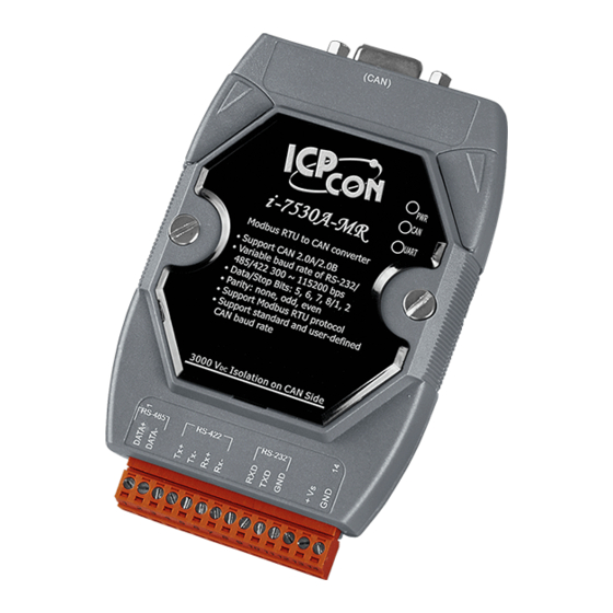
2. Hardware Figure 2-1: Hardware profile of the I-7530A-MR I-7530A-MR Modbus RTU to CAN Converter User’s Manual (Version 1.08, 07/2019) ------------- 9... -
Page 10: Block Diagram
Block Diagram Figure 2-2 is a block diagram illustrating the functions of the I-7530A- MR module. It provides the 3000V Isolation in the CAN and UART interface. And hardware media in RS-232 interface only adopts 3-wire connection. Figure 2-2: Block diagram of I-7530A-MR I-7530A-MR Modbus RTU to CAN Converter User’s Manual (Version 1.08, 07/2019) ------------- 10... -
Page 11: Pin Assignment
Pin Assignment Table 2-1: CAN DB9 Male Connector Description Not Connect CAN Low CAN Ground Not Connect CAN Ground CAN High Not Connect Description RS-485 DATA+ RS-485 DATA- No use RS-422 TxD+ RS-422 TxD- RS-422 RxD+ RS-422 RxD- No use RS-232 RXD RS-232 TXD RS-232 GND... -
Page 12: Hardware Connection
Hardware connection The I-7530A-MR module supports CAN/Serial port communication, it offers one CAN interface for CAN network and RS-232/485/422 interfaces for serial communication. 2.3.1 CAN port connection The pin assignment of the CAN port of the I-7530A-MR (DB9 male) is defined in both the CANopen DS102 profile and in appendix C of the DeviceNet specifications. -
Page 13: Serial Port Connection
2.3.2 Serial port connection The I-7530A-MR offers three serial interfaces. It is recommended to use only one of them at the same time. The following figures describe these port types and the wiring method for a serial device. Figure 2-5: RS-232 Wire Connection Figure 2-6: RS-422 Wire Connection Figure 2-7: RS-485 Wire Connection I-7530A-MR Modbus RTU to CAN Converter User’s Manual (Version 1.08, 07/2019) ------------- 13... -
Page 14: Terminator Resistor Settings
Terminator Resistor Settings According to the ISO 11898 specifications, the CAN Bus network Ω must be terminated by two terminal resistors (120 ). They are shown as following figure. Figure 2-8: Terminal Resistor Therefore, the I-7530A-MR module supplies a jumper for activating the terminal resistor. -
Page 15: Init / Normal Dip-Switch
Enable (default) Disable Figure 2-10: Terminal resistor JP3 Jumper Position Init / Normal Dip-switch On the back of the I-7530A-MR module, there is a DIP-switch used to configure the “firmware operation mode”, “firmware update mode” or “module configuration mode”. The following steps show how to use it. 2.5.1 Firmware Update Mode Please set the DIP-switch to the “Init”... - Page 16 Figure 2-13: CA-0910 Cable Figure 2-14: Firmware downloads connection While updating firmware, users need execute “Firmware_Update_Tool.exe”. The following steps show the update procedure. [1] Run the Firmware_Update_Tool.exe. [2] Choose “COM” interface and “COM Port”. [2] Click “Browser” button to choose the firmware file. (e.g.
-
Page 17: Firmware Operation Mode
Figure 2-15: I-7530A-MR firmware update process The I-7530A-MR firmware can be downloaded from http://ftp.icpdas.com/pub/cd/fieldbus_cd/can/converter/i-7530a-mr/firmware/ The “Firmware_Update_Tool” program can be downloaded from http://ftp.icpdas.com/pub/cd/fieldbus_cd/can/converter/i-7530a-mr/utility/ 2.5.2 Firmware Operation Mode Please set the DIP-switch to the “Normal” position as Figure 2-16 and power on the I-7530A-MR module. The module’s PWR LED always turned on and the others LEDs are turned off. -
Page 18: Module Configuration Mode
Figure 2-16: Normal Position of Dip-Switch 2.5.3 Module Configuration Mode During the module is running in the Firmware Operation Mode, set the DIP-switch to the “Init” (Initial) position as Figure 2-12 and wait for three seconds. The module’s PWR LED still turns on and the others LEDs will flash approximately once per second. - Page 19 (2) CAN LED : It is used to show whether the I-7530A-MR is transmitting/receiving CAN messages. The CAN LED will blink whenever a CAN message is sending or receiving. (3) UART LED : It is used to show whether the I-7530A-MR is transmitting/receiving COM messages.
-
Page 20: Cable Selection
Cable Selection The CAN bus is a balanced (differential) 2-wire interface running over either a Shielded Twisted Pair (STP), Un-shielded Twisted Pair (UTP), or Ribbon cable. The CAN-L and CAN-H Wire start on one end of the total CAN network that a terminator of 120 Ohm is connected between CAN-L and CAN-H. -
Page 21: Software Utility
3. Software Utility The UART2CAN Utility tool can be used to configure the operational conditions of the I-7530A-MR between the CAN and RS-232/485/422 communications. It also can used to transmit or receive a CAN message for simple testing. To start the “UART2CAN Utility”, please install the UART2CAN Utility setup file and run the UART2CAN_Utility.exe file. -
Page 22: Install The Uart2Can Utility
Install the UART2CAN Utility Step 1: Get the UART2CAN Utiltiy The software is located at: Fieldbus_CD:\CAN\Converter\I-7530A-MR\Utility http://ftp.icpdas.com/pub/cd/fieldbus_cd/can/converter/i-7530a-mr/utility/ Step 2: Install .NET Framework 4 Client Profile component The UART2CAN Utility tool requires the Windows Installer 3.1 and the .NET Framework 4 Client Profile components. These components can be obtained from the web site. - Page 23 Step 3: Install Utility tool After installing the .Net Framework components, please run the UART2CAN Utility setup file. 1. Click the “Next” button to continue. Figure 3-3: Setup the UART2CAN Utility. 2. Select the installation path of the UART2CAN Utility and click the “Next”...
- Page 24 3. Confirm the installation. Click the “Next” button to start the installation. Figure 3-5: Confirm Installation. 4. Installation complete. Click the “Close” button to exit. Figure 3-6: Installation complete. I-7530A-MR Modbus RTU to CAN Converter User’s Manual (Version 1.08, 07/2019) ------------- 24...
-
Page 25: Configure The Module Parameters
Configure the module parameters In this section, we will describe how to configure the communication parameters of the I-7530A-MR module with the UART2CAN Utility. 3.2.1 Connect to the I-7530A-MR module with UART2CAN Utility 1. Set the Init/Normal switch to the “Normal” position, which is found on the back of the I-7530A-MR module. -
Page 26: Select The Communication Mode
7. Then the I-7530A-MR configuration window will be brought out. The UART2CAN Utility will show the communication information of the I- 7530A-MR module, as shown in the following figure. Figure 3-8: The configuration form of the I-7530A-MR module. 3.2.2 Select the communication mode The I-7530A-MR supports four communication modes: “Normal”, “Pair connection”, “Modbus Slave”,and “Modbus Master Mode”. -
Page 27: Set The Com Port Parameters
as Modbus Master/CAN module. It can communicate with Modbus slave device via RS-232/485/422. Select Communication mode Figure 3-9: Select Communication Mode. 3.2.3 Set the COM port parameters 1. When the function “Add Checksum” is set to “Yes”, users need to communicate to the I-7530A-MR with checksum mechanism. -
Page 28: Set The Can Parameters
3.2.4 Set the CAN parameters Select the communication parameters of the CAN port and check the “Enable CAN Filter” item to make the CAN filter enable if necessary. About how to set the CAN Filter, please refer to the section 3.3. Figure 3-11: The CAN port of I-7530A-MR configuration. -
Page 29: Set The "Modbus Slave" Parameter
Set the “Modbus Slave” parameter 3.2.6 When users select the “Modbus Slave” communication mode, the functions, “Device ID” and “Specific CAN ID”, are useful. In the “Specific CAN ID” field, users can set maximum 10 CAN IDs (firmware v1.02 or later supports 100 CAN ID of CAN messages). -
Page 30: Configuration Of Default Value
3.2.9 Configuration of default value If users click the “Defaults” button, all of the module communication parameters on the I-7530A-MR will be set to the factory default, which are: Communication Mode = Normal RS232/485/422: Baud rate = 115200 kbps Data Bit Stop Bit Parity = None... -
Page 31: Load/Save The Parameter Configuration
3.2.10 Load/Save the parameter configuration The “Open Parameter File” function provides users to load parameters from existing configuration file (*.INI). And the “Save Parameter from Utility” function provides users to save the current configuration to a file (*.INI). Figure 3-15: Load/Save the parameter configuration from/to file. I-7530A-MR Modbus RTU to CAN Converter User’s Manual (Version 1.08, 07/2019) ------------- 31... -
Page 32: Can Filter Configuration
CAN Filter Configuration There are two parts of the CAN filter configuration. One is “Download CAN Filter” which are used to configure the CAN filter and download the result into the I-7530A-MR module. The other is “Read CAN Filter” which are used to read back the CAN filter configuration from the I-7530A-MR. - Page 33 Figure 3-17 Create CAN filter file Step 2: Add the CAN filter with single CAN ID or group CAN ID. Then, the CAN ID in the list will be received and other CAN IDs which are not in list will be dropped. Add single CAN ID filter Start Add a range of CAN ID filter...
- Page 34 For example, if users want to pass the CAN port with CAN ID 0x07F in the CAN 2.0B specification. Step1: Select “29-bit ID” item in the “CAN Single CAN ID” field. Step2: Fill the value “7F” in the edit box. Step3: Click “Add”...
-
Page 35: Download A Existed Can Filter File
extension file name. Figure 3-20 Five buttons in CAN filter configuration dialog There are five buttons to help users to configure the CAN filter. 1. The “Clear Table” would delete all CAN filter setting in the list. 2. The “Delete Select” would delete the CAN filter setting which users selected. -
Page 36: Read I-7530A-Mr Can Filter Configuration
3.3.3 Read I-7530A-MR CAN Filter Configuration Click the “Read from Module” item on the Utility tool bar to read CAN filter setting from the I-7530A-MR module and save the CAN filter setting as a file (*.FLT). Figure 3-22 Read CAN filter form the I-7530A-MR module Testing the I-7530A-MR module The following procedure will guide users to learn how to transmit/receive CAN messages to/from other devices/PCs by using the I-... - Page 37 Figure 3-23: The configuration for the PC COM port. 7. Press the “Connect” button. Then the UART2CAN Utility will show the diagnostic window, as the figure below. Figure 3-24: Description of diagnostic form 8. Then users can transmit or receive CAN messages via the I-7530A-MR module.
-
Page 38: Normal Mode
In this Utility tool, it supports three communication modes to transmit/receive CAN messages to/from other devices/PCs by using the I- 7530A-MR. There are the Normal mode, Pair connection mode and Modbus Slave mode. In the next section, we will describe how to use it. Figure 3-25: Select communication mode for the Utility. - Page 39 Figure 3-26: The active area of the Utility in Normal mode. The first method (check “Use CAN Message”) requires users to understand what message they want to send. Users need to key-in each part data of a CAN message. The second method (uncheck “Use CAN Message”) allows the use of the command string found in table 4-1 to transmit messages.
- Page 40 If the “Receive” is checked, the messages sent from the I-7530A-MR will automatically be received and displayed in the “Receive” text box. Besides, users can click the “Clear” button to remove the messages in the text box. In addition, users can click the “Save” button to save the CAN “Receive”...
-
Page 41: Pair Connection Mode
3.4.2 Pair Connection Mode The testing Utility screenshot is shown below. Figure 3-29: The active area of the Utility in the Pair connection mode. User can key-in any information to the edit box and select the end of character. Then click the “Send” button to transmit the information to the CAN network. -
Page 42: Modbus Slave Mode
Figure 3-30: The indication of the name in the Pair connection mode. 3.4.3 Modbus Slave Mode In this mode, there are two methods for users to send command to the I-7530A-MR. The screenshot of the Utility is shown below. Modbus Slave Mode Fill Message Received Message Figure 3-31: The active area of the Utility in the Modbus Slave mode. - Page 43 require users to click the “Send” button to transmit the command to the I- 7530A-MR module. When checking the “Timer (ms)”, the Utility will transmit the command periodically. If the “Receive” is checked, the messages sent from the I-7530A-MR will automatically be received and displayed in the “Receive” text box. Besides, users can click the “Clear”...
-
Page 44: Command List (Only For Normal Mode)
4. Command list (Only for normal mode) In order to simplify the application, we provide 9 command strings to send/receive commands through the I-7530A-MR. It can cover most of the applications. The general formats of the commands for the I-7530A- MR are given below: Command Format: <Command>[CHK]<CR>... - Page 45 Checksum algorithm: The checksum [CHK] is 2-characters of the sum of the command message, from the first character to the character before <CR>. For example: Command: Reboot the I-7530A-MR module, “RA[CHK]<CR>”. 1. Sum of the string = ‘R’ + ‘A’ = 52h + 41h = 93h. 2.
-
Page 46: Tiiildd
tIIILDD…[CHK]<CR> Description: Send or receive a standard CAN data frame. Syntax: tIIILDD…[CHK]<CR> Represent a standard (2.0A) data frame. 11 bits Identifier (000~7FF) Data length (0~8) DD… Input data frame value according to the data length (00~FF) Response: Valid command: No response Invalid command: ?<Error Code><CR>... -
Page 47: Eiiiiiiiildd
Send a CAN message with a standard remote frame. ID=2E8, DLC=8. eIIIIIIIILDD…[CHK]<CR> Description: Send or receive an extended CAN data frame. Syntax: eIIIIIIIILDD…[CHK]<CR> Stands for the extended (2.0B) data frame. IIIIIIII 29 bits Identifier (00000000~1FFFFFFF) Data length (0~8) DD… Input data frame value according to the data length (00~FF) ... -
Page 48: S[Chk]
the UART2CAN Utility in order to receive Syntax and/or communication error information. Example: Command: E010156786<CR> Send a CAN message with an extended remote frame. ID=01015678, DLC=6. S[CHK]<CR> Description: Read the I-7530A-MR CAN baud rate and error flag message. Syntax: S[CHK]<CR> Command character. -
Page 49: P0Bbdspcr[Chk]
125K baud rate of CAN 250K baud rate of CAN 500K baud rate of CAN 800K baud rate of CAN 1000K baud rate of CAN User-defined baud rate of CAN Table 4-3: CAN status register list AsciiToHex(FF) Description Bit 7 Bus Status (0: Bus-On, 1: Bus-Off) Bit 6 Error Status (0: OK, 1: Error) - Page 50 Command character RS-232/485/422 Baud rate Data bit 0 = 5 bits Data formation 1 = 6 bits Data formation 2 = 7 bits Data formation 3 = 8 bits Data formation Stop bit (0=1 stop bit, 1=2 stop bits) Parity (0=None, 1=Odd, 2=Even) Checksum (0=No, 1=Yes) Other response Table 4-5: RS-232/485/422 baud rate list...
- Page 51 Response: A valid command will write the RS-232/485/422 configuration parameters into the EEPROM and then reboot the I-7530A-MR module. Invalid command: ?<Error Code><CR> Note: It is necessary to enable the “Error Response” function while using the UART2CAN Utility in order to receive Syntax and/or communication error information.
-
Page 52: P1B [Chk]
P1B [CHK]<CR> Description: Change the CAN Baud rate configuration of the I-7530A-MR module and then reboot the I-7530A-MR module. Syntax: P1B[CHK]<CR> Command character CAN Baud rate Table 4-7: CAN baud rate list Description 10 kbps baud rate of CAN 20 kbps baud rate of CAN 50 kbps baud rate of CAN 100 kbps baud rate of CAN... -
Page 53: P2Bbbbb[Chk]
P2BBBBB[CHK]<CR> Description: Change the user-defined CAN baud rate configuration of I-7530A- MR module and then reboot the I-7530A-MR module. Syntax: P2BBBBB[CHK]<CR> Command character BBBBB User-defined CAN baud rate Response: A valid command will write the user-defined CAN baud rate configuration into the EEPROM and then reboot the I-7530A-MR module. -
Page 54: Ra[Chk]
RA[CHK]<CR> Description: Reboot the I-7530A-MR module. This command is usually used while the status of CAN bus is bus-off. In this case, users can use this command to reboot the module to work it again. Syntax: RA[CHK]<CR> Command character ... -
Page 55: General Error Code For All Command
General Error code for all command 4.10 If the Error response function on the I-7530A-MR_MR module is set to be “Yes”(that means enable) via the I-7530A-MR Utility when configuration, the I- 7530A-MR will automatically send the error code to the RS-232/485/422 device or the host PC through the RS-232/485/422 media when the I-7530A-MR produces an error message during the operation mode. -
Page 56: Pair-Connection Mode Description
Pair-connection Mode Description The pair connection function usually needs two I-7530A-MRs. When these two I-7530A-MRs are in pair connection mode, all RS-232/485/422 commands transmitted from one of these two I-7530A-MRs will be put in the data field of CAN message. This CAN message will be transferred to RS-232/485/422 commands by another I-7530A-MR. - Page 57 The CAN ID in above figure is determined by the CAN specification selected by users. If users select CAN 2.0A, the CAN ID is 11-bit ID. If CAN 2.0B is used, the CAN ID is 29-bit ID. Here, assume users set the Fixed Tx CAN ID field of I-7530A-MR#1 to be 0x001 ( “0x”...
- Page 58 Application 2: This application architecture is the same as the one of application1. The application architecture is show below. The difference will be discussed in the following paragraph. Figure 5-2: The diagram of Application 2. Configurations: To apply this application, user need to configure the I-7530A-MR#1 and I- 7530A-MR#2 as follows.
- Page 59 Application 3: This application may be used to construct a RS-232 device network via CAN bus. The architecture is shown below. Figure 5-3: The diagram of Application 3. Configurations: In order to apply this application, users need to configure the I-7530A-MR#1, I-7530A-MR#2, and I-7530A-MR#3 as follows.
- Page 60 Figure 5-5: I-7530A-MR#2 Configuration. Figure 5-6: I-7530A-MR#3 Configuration. Communication Descriptions: When the Device1 want to transmit the RS-232 command “1234567” to Device2, the command written to I-7530A-MR#1 by the Device1 needs to be “0021234567” because the Device1 is set to dynamic Tx CAN ID (Fixed Tx CAN ID is not checked).
- Page 61 commands “002456789” or “003456789”. Therefore, Device1 can decide the target device which RS-232 commands will be sent to. Also, Device1 knows where the RS-232 commands come from. The general concept of transmitting data from Device1 to Device2 is shown below. Note: In pair connection mode, all command strings listed in the section 4 are useless.
-
Page 62: Modbus Slave Mode
6.Modbus Slave Mode The I-7530A-MR, Modbus RTU to CAN converter, supports the Modbus RTU protocol. It can act as a Modbus RTU slave on the Modbus network. There are some mechanisms for data-exchanging between the CAN register and the Modbus RTU register as the figure at the next page. In the Modbus Input Register, according to the different purposes these register are divided into three fields, “Normal CAN Message Field”, “Specific CAN Message Field”... - Page 63 Figure 6-1: Architecture diagram for the Modbus mode. I-7530A-MR Modbus RTU to CAN Converter User’s Manual (Version 1.08, 07/2019) ------------- 63...
-
Page 64: Supported Modbus Functions
Supported Modbus Functions The Modbus function codes supported by the I-7530A-MR are shown in the following table. Table 6-1: Supported Modbus Function Codes Function Code Function Name Description Reading Output Read multiple registers for a sent 3 (03 Hex) Register CAN messages Reading Input Read multiple input registers for... - Page 65 Figure 9-2: The address definition of Input Register and Output Register of the I-7530A-MR. Modbus Input Register: (1) Normal CAN Message Field: In this field, the address range of “Normal CAN Message” is 00000~01799 (protocol addresses). It is used to store the CAN message received from the CAN network.
- Page 66 Table5-2: Modbus address arrangement of “Normal CAN Message” field. Protocol Addresses PLC Addresses Word Description (Base 0) (Base 1) Count Decimal rule 00000 ~ 00008 30001 ~ 30009 RX CAN Message #001 00009 ~ 00017 30010 ~ 30018 RX CAN Message #002 …...
- Page 67 (2) Module Status Field: The I-7530A-MR’s status information is defined in the following address. Users can use the Modbus RTU command (function code 04 ) to read these informations from the “Module Status” field. Table5-3: Modbus address of “Modbus Status” field. Protocol Addresses PLC Addresses Word...
- Page 68 Most significant byte: CAN receive error counter. CAN Error Counter Least significant byte: CAN transmit error counter. CAN/UART Bit 0: CAN overflow flag, 0Not full, 1 Full. Overflow flag Bit 1: UART overflow flag, 0Not full, 1 Full. Most significant byte major field of firmware version Least significant byte ...
- Page 69 (3) Specific CAN Message Field: The I-7530A-MR supports a “Specific CAN Message” field to store ten special CAN messages with specific the CAN IDs(Note1). When the I- 7530A-MR receive the CAN messages whose CAN IDs are defined in the Specific CAN Message Field by the Utility tool, the I-7530A-MR put this CAN message into the corresponding register of the Specific CAN Message field.
- Page 70 Modbus Output Register: There are two fields on Modbus output register, one is TX CAN message field and the other is Configuration command field. The addresses of these fields are described below. Table5-5: Modbus output register address Protocol Address PLC Address Description (Base 0) (Base 1)
- Page 71 (2) Configuration command Field: The “Configuration command” in the Modbus Output Register is used for user to use Modbus command to configure module, including reboot module, reset CAN bus, change RS-232/RS-422/RS-485 setting, change CAN bus baud rate, change user-defined CAN baud rate. These configuration commands are described below: 1.
- Page 72 2. Reset CAN bus This command is used to reset CAN bus of module. After successfully setting, the module will response a successful setting message. Request command: Field Name Size Value Range Example Hexadecimal rule Node ID 1 byte 0x01~0xF7 0x01 Function Code 1 byte...
- Page 73 3. Change RS-232/RS-422/RS-485 setting This command is used to Change RS-232/RS-422/RS-485 setting. After successfully setting, the module will response a successful setting message, and then reboots. Request command: Field Name Size Value Range Example Hexadecimal rule Node ID 1 byte 0x01~0xF7 0x01 Function Code...
- Page 74 0x000B 115200 bps baud rate of RS-232/RS-422/RS-485. 0x000C 230400 bps baud rate of RS-232/RS-422/RS-485. Note3: This value is Data bit of RS-232/RS-422/RS-485. Data bit Description Hexadecimal rule 0x0000 5 bits Data formation 0x0001 6 bits Data formation 0x0002 7 bits Data formation 0x0003 8 bits Data formation Note4: This value is Stop bit of RS-232/RS-422/RS-485.
- Page 75 4. Change CAN bus baud rate This command is used to Change CAN bus baud rate. After successfully setting, the module will response a successful setting message, and then reboots. Request command: Field Name Size Value Range Example Hex rule Node ID 1 byte 0x01~0xF7...
- Page 76 Response command: Field Name Size Value Range Response Example Hexadecimal rule Node ID 1 byte 0x01~0xF7 0x01 Function Code 1 byte 0x10 0x10 Start Address 2 bytes 0x0100 0x0100 Word Count 2 bytes 0x0002 0x0002 I-7530A-MR Modbus RTU to CAN Converter User’s Manual (Version 1.08, 07/2019) ------------- 76...
- Page 77 5. Change user-defined CAN bus baud rate This command is used to Change user-defined CAN bus baud rate. After successfully setting, the module will response a successful setting message, and then reboots. Request command: Field Name Size Value Range Example Hex rule Node ID 1 byte...
- Page 78 Field Name Size Value Range Response Example Hexadecimal rule Node ID 1 byte 0x01~0xF7 0x01 Function Code 1 byte 0x10 0x10 Start Address 2 bytes 0x0100 0x0100 Word Count 2 bytes 0x0003 0x0003 I-7530A-MR Modbus RTU to CAN Converter User’s Manual (Version 1.08, 07/2019) ------------- 78...
-
Page 79: Using Modbus Rtu Command To Get A Can Message
6.2.1 Using Modbus RTU command to get a CAN Message When the I-7530A-MR is set to the Modbus Slave mode, each CAN message (except the CAN message whose CAN IDs are defined in the Specific CAN Message field) received from the CAN network will be stored into the “Normal CAN Message”... - Page 80 Example2: Use Modbus RTU command (function code 04 ) to read two CAN messages: Figure 6-4: Use the Modbus command to read two CAN message. I-7530A-MR Modbus RTU to CAN Converter User’s Manual (Version 1.08, 07/2019) ------------- 80...
-
Page 81: Using Modbus Rtu Command To Send A Can Message
6.2.2 Using Modbus RTU command to send a CAN message If users need to send CAN messages via the Modbus RTU commands, users need to send the Modbus RTU command with the “TX CAN message“ format to the Output Register of the I-7530A-MR. Then the I-7530A-MR will transfer this command to a CAN message format and send it to the buffer of the CAN controller. - Page 82 Users can use the Modbus RTU command with function code 03 to read the transmitted CAN message. The start address of the command is always 0000 and the data length field must be set to 0007 hex, Example: Use the Modbus RTU command (function code 03 ) to read the transmitted CAN message format from the Output Register: Figure 6-6: Use the Modbus RTU command (function code 03...
-
Page 83: Hex To Send A Can Message
6.2.2.2 Using function Code 06 to send a CAN message Users can use Modbus RTU commands (function code 06 ) to transmit a CAN message by writing the Output Register of the I-7530A-MR (the data format must follow the table 5-5). The start address of the Modbus command is always 0000 . - Page 84 I-7530A-MR Modbus RTU to CAN Converter User’s Manual (Version 1.08, 07/2019) ------------- 84...
- Page 85 Note: Using function code 03 to read a output CAN message is not allowed when you use this method to transmit a CAN message. I-7530A-MR Modbus RTU to CAN Converter User’s Manual (Version 1.08, 07/2019) ------------- 85...
-
Page 86: Using Modbus Rtu Command To Get A Specific Can Message
6.2.3 Using Modbus RTU command to get a Specific CAN Message The I-7530A-MR supports a “Specific CAN Message” field to get the expect ten specific CAN messages(firmware v1.02 or later support 100 CAN ID of CAN messages). When receiving a CAN message whose CAN ID is defined in the Specific CAN Message by the Utility tool, the I-7530A-MR will save this CAN message to the “Specific CAN Message”... -
Page 87: Using Modbus Rtu Command To Configure Module
6.2.4 Using Modbus RTU command to configure module I-7530A-MR supports five Modbus RTU commands (function code 10 ) of configuring module, including reboot module, reset CAN bus, change RS- 232/RS-422/RS-485 setting, change CAN bus baud rate, and change CAN bus user-defined baud rate. - Page 88 Example: Using Modbus RTU command to change user-defined CAN bus baud rate. Figure 6-9: Using Modbus RTU command to change user-defined CAN baud rate. I-7530A-MR Modbus RTU to CAN Converter User’s Manual (Version 1.08, 07/2019) ------------- 88...
-
Page 89: Modbus Exception Codes
Modbus Exception Codes The following table lists the Modbus Exception codes that the I-7530A-MR supports. Table 6-6: Error code table code Description Possible causes & solutions The function code is not an allowable action Illegal function for the I-7530A-MR. The data address is not allowed for the I- Illegal Data Address 7530A-MR. -
Page 90: Modbus Master Mode
7. Modbus Master Mode To compare with the chapter 5, this section will introduce the Modbus master mode of the I-7530A-MR. Via this function, the I-7530A-MR can act as a Modbus master to CAN module. Following, this sector will illustrate how to configure and how to operate the function in detail. -
Page 91: Io Memory Size
IO Memory Size The Modbus Master function uses two memory spaces for storing input data from Modbus slave and output data from CAN device. One is called “Read Memory Space” and the other is called “Write Memory Space”. Both of these two input/output data spaces are maximum 2048 bytes. -
Page 92: Modbus Read Configuration
Modbus Read Configuration Modbus Write Configuration Common Configuration The above screenshots are the operating interface of the I-7530A-MR Modbus Master configuration. The operating interface is divided into three parts “Modbus Read Configuration”, “Modbus Write Configuration”, and “Common Configuration”. 7.3.1 Modbus Read Configuration Modbus Read Command List I-7530A-MR Modbus RTU to CAN Converter User’s Manual (Version 1.08, 07/2019) ------------- 92... -
Page 93: Modbus Read Command
This page is used for configuring “Modbus Read Command” and “Response CAN Message”. The major purpose of the “Modbus Read Command” is access Modbus slave device via “Modbus Read Coil” or “Modbus Read Registers” command. And the major purpose of the “Response CAN Message”... - Page 94 Therefore, before using this configuration, you must know what is the Modbus Read Coil/Registers format that the Modbus slave devices supported. Slave Node ID: Set the slave Node ID which you want to access. Function Code: In this setting interface, it supports the Modbus function code 0x01, 0x02, 0x03, and 0x04.
- Page 95 Bit Count(Low): This field indicates low byte of the number of bits which you want to read. Note: When using function code 0x03 or 0x04, this field will be the number of words (low byte). Add: After setting the “Modbus Read Command, please click this button to add it into command list.
-
Page 96: Response Can Message Configuration
7.3.1.2 Response CAN Message Configuration This function is used for configuring “Response CAN message” which you want to reply Modbus slave IO data via CAN bus. After setting, the CAN message with IO data will actively or passively be replied to CAN Bus by I-7530A-MR. - Page 97 For example: If you want to use CAN ID 0x123 to reply 8 byte IO data. If the “Passively Response” is checked, the other CAN device needs to send a RTR frame with CAN ID 0x123 and then the I-7530A- MR will reply to a CAN message with IO data.
- Page 98 Mapping CAN ID: This field indicates the hexadecimal value of the CAN ID. IO Data Byte Count: This field indicates the data length of the CAN message. The maximum value of byte count is 8 bytes due to the data length limitation of the CAN message.
-
Page 99: Modbus Write Configuration
7.3.2 Modbus Write Configuration Modbus Write Command List This page is used for configuring the “Modbus Write Command”. After setting done, the related parameters will be stored into the I-7530A-MR module. When I- 7530A-MR is rebooted on operating mode, it will load these parameters and check received CAN messages for transmitting a “Modbus Write Command”. - Page 100 CAN Specification: This field indicates this CAN message uses CAN 2.0A or CAN 2.0B. If the CAN 2.0A is selected, the maximum value of CAN ID is 0x7FF. Relatively, if the CAN 2.0B is selected, the maximum value of CAN ID is 0x1FFFFFFF.
- Page 101 Function Code: In this setting interface, it supports the function code 0x05, 0x06, 0x0F, and 0x10. Start Address (High): This field indicates the high byte of Modbus reference IO data address. Start Address (Low): This field indicates the low byte of Modbus reference IO data address. ...
- Page 102 Add: Click this button to add a Modbus write command into “Write Command List”. The current configuration will be shown on the list. It includes CAN specification, value of CAN ID, and Modbus RTU Write command. After you add a Modbus write command, the command will occupy a part of the “Write Memory Space”.
-
Page 103: Common Configuration
7.3.3 Common Configuration CAN Error Response Message: CAN Error Response: This function is used to transmit an error message via CAN bus when the Modbus communication error or command timeout is detected. When this function is checked, the “CAN Specification” field and “Error Response CAN ID”... - Page 104 It indicates the current Modbus command is 0x03 transmitted completely, but the I-7530A-MR receives a “Modbus Exception” command. From Data Byte4 to Data Byte7, they indicate the “Modbus Exception” message. The “Modbus Exception” message includes Slave Node ID, Exception Function Code, and Exception Code. When the Identifier code is 0x03, this message is shown in the error response CAN message.
- Page 105 occurred. If there is no response, this Modbus command will be regarded as a timeout status. Afterward, the next Modbus command will be sent. Save Configuration: This button is used to save “Modbus Read Configuration”, “Modbus Write Configuration”, and “Common Configuration” settings into the I- 7530A-MR。After complete setup, please remember to chick this button to save all configurations.
-
Page 106: Example
Example 7.3.4 Modbus RTU Command :01 04 00 00 00 08 CAN 2.0A: 0x1B0, 0x1B1 , Error Response CAN ID:0x666 I-7530A-MR Modbus RTU to CAN Converter User’s Manual (Version 1.08, 07/2019) ------------- 106... -
Page 107: Uart Switch Descption(Uart Switch Mode)
8.Uart Switch Descption(Uart Switch Mode) To facilitate the application of custom protocols, the I-7530A-MR provides Uart Switch mode. In the mode, Users can transfer data in Binary format on the UART side. According to the requirements, set the "CAN-ID Offset" and CAN- ID Length". -
Page 108: Can To Uart
8.2 CAN to Uart When a CAN message is received, it will be converted to UART Binary data immediately. I-7530A-MR Modbus RTU to CAN Converter User’s Manual (Version 1.08, 07/2019) ------------- 108... -
Page 109: Direction
8.3 Direction In order to reduce Bus Loading, Uart Switch mode provides "Uart->CAN" and "CAN-> UART" one-way communication options. 8.4 One-to-many application Set the "CAN-ID Offset" and “CAN-ID Length" for I-7530A-MR and set the CAN-ID Filter for CAN device. Figure 8-1: Application concept I-7530A-MR Modbus RTU to CAN Converter User’s Manual (Version 1.08, 07/2019) ------------- 109... -
Page 110: Troubleshooting
9.Troubleshooting (1) Why the module’s PWR LED flashes quickly: If the I-7530A-MR CAN baud rate is not the same as the CAN baud rate of the CAN bus network, the PWR LED of the I-7530A-MR will flash one per 100ms because the I-7530A-MR cannot send any CAN message to the CAN bus network. - Page 111 devices, users need to choose a set of proper CAN parameter (BTR0 & BTR1) for communication compatible with I-7530A-MR and the rule is as follows: (1) The “Samples” value is 1. (1) The “SJW” value is as small as possible. (1 is the best). (2) The “Tseg2”...
Need help?
Do you have a question about the I-7530A-MR-G and is the answer not in the manual?
Questions and answers