ICP DAS USA I-7530 User Manual
Rs-232/can converter
Hide thumbs
Also See for I-7530:
- User manual (101 pages) ,
- Quick start manual (9 pages) ,
- Quick start user manual (7 pages)
Table of Contents
Advertisement
Quick Links
ГК Атлант Инжиниринг – официальный представитель в РФ и СНГ
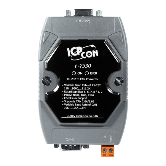
The I-7530 RS-232/CAN Converter
Warranty
All products manufactured by ICP DAS are under warranty regarding
defective materials for a period of one year from the date of delivery to the
original purchaser.
Warning
ICP DAS assumes no liability for damages resulting from the use of
this product. ICP DAS reserves the right to change this manual at any
time without notice. The information furnished by ICP DAS is believed to
be accurate and reliable. However, no responsibility is assumed by ICP
DAS for its use, or for any infringements of patents or other rights of third
parties resulting from its use.
Copyright
Copyright 1997 by ICP DAS. All rights are reserved.
Trademark
The names used for identification only may be registered trademarks
of their respective companies.
I-7530 RS-232/CAN Converter User's Manual (Version 1.0,Aug/2004, 7PH-021-01) ------------- 1
+7(495)109-02-08 sales@bbrc.ru www.bbrc.ru
User's Manual
Advertisement
Table of Contents

Related Manuals for ICP DAS USA I-7530


Summary of Contents for ICP DAS USA I-7530
- Page 1 Copyright Copyright 1997 by ICP DAS. All rights are reserved. Trademark The names used for identification only may be registered trademarks of their respective companies. I-7530 RS-232/CAN Converter User’s Manual (Version 1.0,Aug/2004, 7PH-021-01) ------------- 1...
-
Page 2: Table Of Contents
TIIIL[CHK]<CR> ................18 eIIIIIIIILDD…[CHK]<CR>..............19 EIIIIIIIIL[CHK]<CR> ................19 S[CHK]<CR> ..................20 C[CHK]<CR> ..................22 P0BBDSPAE[CHK]<CR> ..............22 P1B [CHK]<CR>................23 RA[CHK]<CR>.................. 24 4.10 General Error code for all command..........25 Troubleshooting ....................25 I-7530 RS-232/CAN Converter User’s Manual (Version 1.0,Aug/2004, 7PH-021-01) ------------- 2... -
Page 3: Introduction
HMI to access/control the CAN device through the CAN network by the I- 7530 Converter. The programmable RS-232 device (For example: I- 8411/I-8431/I-8811/I-8831/W-8031/W-8331/W-8731 embedded controller) can use the serial port to connect to the CAN network via the I-7530 module. Figure 1: Application of I-7530 In order to use the CAN network with traditional RS-232 devices, we provide a way to achieve this goal. -
Page 4: Features
• Unregulated +10V DC ~ +30V DC; • Power reverse protection, Over-Voltage brown-out protection; • Power consumption: 1W; Module specs: • Dimensions: 123mm x 72mm x 33mm; • Operating temperature: -25 to 75ºC (14 to 185ºF); I-7530 RS-232/CAN Converter User’s Manual (Version 1.0,Aug/2004, 7PH-021-01) ------------- 4... -
Page 5: Hardware
• Vehicle Automation; 2. Hardware 2.1 Block Diagram Figure 2 is a block diagram illustrating the functions on the I-7530 module. It provides the 3000Vrms Isolation in the CAN interface site. And hardware media in RS-232 interface is only adopted 3-wire connection. -
Page 6: Pin Assignment
Table 1: RS-232 DB9 Female Connector (CN1) Terminal 3-wire RS-232 Not Connect Not Connect Not Connect Table 2: CAN DB9 Male Connector (CN2) Terminal 2-wire CAN Not Connect CAN Low Not Connect CAN High Not Connect I-7530 RS-232/CAN Converter User’s Manual (Version 1.0,Aug/2004, 7PH-021-01) ------------- 6... -
Page 7: Hardware Connection
+7(495)109-02-08 sales@bbrc.ru www.bbrc.ru Figure 3: Pin Assignment on the I-7530 Hardware connection The RS-232 port on the I-7530 (DB9 female) is inserted directly into a PC’s COM serial port or via a cable to the Host system. Figure 4: RS-232 connection... -
Page 8: Terminator Resistor Settings
ГК Атлант Инжиниринг – официальный представитель в РФ и СНГ +7(495)109-02-08 sales@bbrc.ru www.bbrc.ru The pin assignment of the CAN port on the I-7530 (DB9 male) defined in both the CANopen DS102 profile and in appendix C of the DeviceNet specifications. It is the standard pin assignment for CAN. -
Page 9: Init/Normal Dip-Switch
If users want to use this terminator resistor, please open the I-7530 cover and use the JP3 jumper to activate the 120 Ω terminator resistor built in the system, as in the following figure. Note that the default setting is active. -
Page 10: Led Indication
+7(495)109-02-08 sales@bbrc.ru www.bbrc.ru switch to the “Normal” position. Users need to turn the power off then on again so that they can use the I-7530 in the operation mode. Once you have completed your configurations and have switched to the operation mode, then messages can pass between the CAN and the RS-232. -
Page 11: Cable Selection
Furthermore, If users want to check what the error situation is they must send the command string “S[CHK]<CR>”. Depending on the result, users will need to either reboot the I-7530 or use the command string “C[CHK]<CR>” to clear the FIFO flag, which will then turn off the ERR LED. -
Page 12: Software Utility
7530 Utility”, please run the I7530.exe file. The screenshot of the startup screen for this Utility is given in the below figure. Connect the I-7530’s COM port with the PC’s COM port via a RS-232 cable. Then the user can connect the CAN interface into the CAN network based on the CAN specifications. -
Page 13: How To Configure The Module Parameters
PC and the I-7530 via the COM port. 5. Click the “Settings…” icon on the I-7530 Utility tool bar in order to select which PC COM port will be used to connect to the I-7530 COM port, as shown in the following figure. - Page 14 +7(495)109-02-08 sales@bbrc.ru www.bbrc.ru Figure 12: COM port setting 6. Click the “Connect” icon to bring out the I-7530 configuration window. The I-7530 Utility will show the communication information from the I- 7530 module in the window, as shown in the following figure.
-
Page 15: How To Test The Module Transmission Performance
3. Supply the 10~30 volts DC source into the I-7530 module through the power terminal. 4. The ON LED on the I-7530 module will be turned on. That means the I- 7530 is working in the operation mode. 5. Run the I-7530 Utility software after there is a wire connection as shown in Section 1.5. - Page 16 Figure 14: COM port setting 7. Click the “Connect” icon to connect to the I-7530’s testing mode. Then the I-7530 Utility will show the test tab in the window as can be seen in the below figure. Figure 15: Connect to the operation mode of I-7530 8.
-
Page 17: Command List
4. Command list For easy application, we provide 9 command strings to allow users to send and receive commands and responses through the I-7530. It can cover most applications of different requests. The general format of the commands for the I-7530 are given below: Command Format: <Command>[CHK]<CR>... -
Page 18: Tiiildd
Invalid command: ?<Error Code><CR> Note: It is necessary to enable the “Error Response” function in the I- 7530 Utility, in order to receive Syntax and/or communication error information at the host PC. I-7530 RS-232/CAN Converter User’s Manual (Version 1.0,Aug/2004, 7PH-021-01) ------------- 18... -
Page 19: Eiiiiiiiildd
DLC=5, data1=11, data2=22, data3=33, data4=44 and data5=55. EIIIIIIIIL[CHK]<CR> Description: Send or receive an extended CAN remote frame. Syntax: EIIIIIIIIL[CHK]<CR> Stands for the extended (2.0B) CAN remote frame. IIIIIIII 29 bits Identifier (00000000~1FFFFFFF) Data length (0~8) I-7530 RS-232/CAN Converter User’s Manual (Version 1.0,Aug/2004, 7PH-021-01) ------------- 19... -
Page 20: S[Chk]
Example: Command: E010156786<CR> Send a CAN message with an extended remote frame. ID=01015678, DLC=6. 4.5 S[CHK]<CR> Description: Read the I-7530 CAN Baud Rate and error flag message. Syntax: S[CHK]<CR> Command character. Response: Valid Command: !CFFTTRRO[CHK]<CR> Invalid command: ?<Error Code>[CHK]<CR> Delimiter for valid command... - Page 21 Obtain some current information on the I-7530 module. The response will show the following results: CAN baud rate=250K, CAN register= normal, CAN transmit error counter=0, CAN receive error counter=0 and CAN/RS232 FIFO= normal. I-7530 RS-232/CAN Converter User’s Manual (Version 1.0,Aug/2004, 7PH-021-01) ------------- 21...
-
Page 22: C[Chk]
7530 Utility, in order to receive Syntax and/or communication error information at the host PC. Example: Command: C<CR> 4.7 P0BBDSPAE[CHK]<CR> Description: Change the RS-232 configuration on the I-7530 module and then reboot the I-7530 module. Syntax: P0BBDSPCE[CHK]<CR> Command character RS-232 Baud rate... -
Page 23: P1B [Chk]
Example: Command: P00B30000<CR> Set the RS232 baud rate=115.2K, data bit=8, stop bit=1, none parity, no checksum and No error responses into the I-7530 module and then reboot the I-7530 module. 4.8 P1B [CHK]<CR> Description: Change the CAN configuration of I-7530 module and then reboot the I-7530 module. -
Page 24: Ra[Chk]
I-7530 module. 4.9 RA[CHK]<CR> Description: Reboot the I-7530 module. If the module is displaying on but the CAN bus is off, users can use this command to reboot the module in order to allow it to work in order again. -
Page 25: General Error Code For All Command
If the Error response function on the I-7530 module is set to be “Yes”(that means enable) via the I-7530 Utility during the configuration period, the I-7530 will send the error code to the RS-232 device of the host PC through the RS-232 media when the I-7530 produces an error message automatically during the operation mode. - Page 26 Error: T0018 Right: T0018<CR> If the I-7530 CAN baud rate is not the same as the CAN baud rate on the CAN network, the data flow LED on the I-7530 will be flash with a constant frequency because the I-7530 cannot send any CAN messages to the CAN network.
Need help?
Do you have a question about the I-7530 and is the answer not in the manual?
Questions and answers