ICP DAS USA I-7530A User Manual
Hide thumbs
Also See for I-7530A:
- User manual (101 pages) ,
- User manual (68 pages) ,
- User manual (69 pages)
Table of Contents
Advertisement
Quick Links
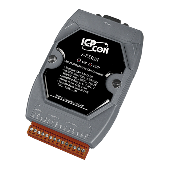
The I-7530A RS-232/485/422 to CAN
Warranty
All products manufactured by ICP DAS are under warranty regarding
defective materials for a period of one year from the date of delivery to the
original purchaser.
Warning
ICP DAS assumes no liability for damages resulting from the use of
this product. ICP DAS reserves the right to change this manual at any
time without notice. The information furnished by ICP DAS is believed to
be accurate and reliable. However, no responsibility is assumed by ICP
DAS for its use, or for any infringements of patents or other rights of third
parties resulting from its use.
Copyright
Copyright 2008 by ICP DAS. All rights are reserved.
Trademark
The names used for identification only may be registered trademarks
of their respective companies.
I-7530A RS-232/485/422 to CAN Converter User's Manual (Version 1.2, Sep/2011) ------------- 1
Converter
User's Manual
Advertisement
Table of Contents

Related Manuals for ICP DAS USA I-7530A


Summary of Contents for ICP DAS USA I-7530A
- Page 1 Copyright Copyright 2008 by ICP DAS. All rights are reserved. Trademark The names used for identification only may be registered trademarks of their respective companies. I-7530A RS-232/485/422 to CAN Converter User’s Manual (Version 1.2, Sep/2011) ------------- 1...
-
Page 2: Table Of Contents
30 EIIIIIIIIL[CHK]<CR> ................31 S[CHK]<CR> ..................32 C[CHK]<CR> ..................34 P0BBDSPAE[CHK]<CR> ..............35 P1B [CHK]<CR>................37 RA[CHK]<CR>.................. 38 4.10 General Error code for all command..........38 Troubleshooting ....................39 I-7530A RS-232/485/422 to CAN Converter User’s Manual (Version 1.2, Sep/2011) ------------- 2... -
Page 3: T1. Introduction
RS-232/485/422 devices such as PC, I-8411/I-8431/I- 8811/I-8831 embedded controllers, can be the master of a CAN network. Therefore, they can control or monitor the CAN devices via the I-7530A module. Moreover, we expand the functionalities of I-7530A for some special application. -
Page 4: Features
• CAN interface connector: D-sub 9-pin male • CAN Baud Rate: 10K, 20K, 50K, 100K, 125K, 250K, 500K, 800K and 1M bps • Isolation voltage: 3000Vrms on the CAN side I-7530A RS-232/485/422 to CAN Converter User’s Manual (Version 1.2, Sep/2011) ------------- 4... - Page 5 • Provide a quick testing function for transmitting/receiving CAN messages Application: • Factory Automation • Building Automation • Home Automation • Control system • Monitor system • Vehicle Automation I-7530A RS-232/485/422 to CAN Converter User’s Manual (Version 1.2, Sep/2011) ------------- 5...
-
Page 6: Hardware
2. Hardware 2.1 Block Diagram Figure 1 is a block diagram illustrating the functions on the I-7530A module. It provides the 3000Vrms Isolation in the CAN interface site. And hardware media in RS-232 interface is only adopted 3-wire connection. Figure 1: Block diagram of I-7530A... - Page 7 Table 2: CAN DB9 Male Connector (CN2) Terminal 2-wire CAN Not Connect CAN Low Not Connect CAN High Not Connect Figure 2: Pin Assignment of the I-7530A I-7530A RS-232/485/422 to CAN Converter User’s Manual (Version 1.2, Sep/2011) ------------- 7...
-
Page 8: Hardware Connection
Hardware connection The RS-232 port on the I-7530A is inserted directly into a PC’s COM serial port or via a cable to the Host system. Figure 3: RS-232 connection The pin assignment of the CAN port on the I-7530A (DB9 male) defined in both the CANopen DS102 profile and in appendix C of the DeviceNet specifications. -
Page 9: Terminator Resistor Settings
Therefore, the I-7530A module supplies a jumper for users to connect the terminator resistor or not. If users want to use this terminator resistor, please open the I-7530A cover and use the JP3 jumper to activate the 120Ω terminator resistor built in the system, as in the following figure. -
Page 10: Init/Normal Dip-Switch
Init/Normal Dip-switch On the back of the I-7530A module, there is a dip-switch used for setting the operation or configuration mode of the module function. In the normal situation, the user needs to first make a configuration in order to provide the correct function when the module works in the operation mode. -
Page 11: Led Indication
CAN controller has been alerted, the ERR LED will turn on. In this case, users can only reboot the I-7530A module in order to turn off the ERR LED. If the CAN or RS232/485/422 FIFO overflows, the ERR LED will also be turned on. -
Page 12: Cable Selection
(heavier) the wire, the lower the number. For example: a 24AWG wire is thicker/heavier than a 26AWG wire. I-7530A RS-232/485/422 to CAN Converter User’s Manual (Version 1.2, Sep/2011) ------------- 12... -
Page 13: Software Utility
3. Software Utility This section will show you how to configure the I-7530A and test it by using I-7530 Utility. Users can download I-7530 Utility software from the ICP DAS web site: http://www.icpdas.com/products/Remote_IO/can_bus/i- 7530A.htm, or get this information from the ICP DAS Fieldbus CD-ROM. -
Page 14: How To Configure The Module Parameters
That means the I-7530A module is working in the configuration mode. 4. Run the I-7530A’s Utility software after connect the PC COM port and the I-7530A COM port by a RS-232 cable. 5. Click the “Connect” icon on the I-7530A Utility tool bar. The setting frame will be popped up. - Page 15 Note: If the I-7530A is in the Init mode or users choose the “Settings” tab, they can only communicate with each other by using 115200 Baud. 6. Then the I-7530A configuration window will be brought out. The I-7530 Utility will show the communication information from the I-7530A module in the window.
- Page 16 3.4. 9. Once users have finished all parameter settings, please click the “Setting” button to store the communication parameters into the EEPROM on the I-7530A. I-7530A RS-232/485/422 to CAN Converter User’s Manual (Version 1.2, Sep/2011) ------------- 16...
- Page 17 = No Error Response = No CAN: CAN Specification = 2.0A CAN bus Baudrate = 125K Acceptance Code = 000 Acceptance Mask = 000 Pair Connection = None I-7530A RS-232/485/422 to CAN Converter User’s Manual (Version 1.2, Sep/2011) ------------- 17...
-
Page 18: How To Set The Acceptance Code And Mask
CAN 2.0A and CAN 2.0B is the CAN ID bits. In CAN 2.0A: number of CAN ID bits is 11. In CAN 2.0B: number of CAN ID bits is 29. I-7530A RS-232/485/422 to CAN Converter User’s Manual (Version 1.2, Sep/2011) ------------- 18... -
Page 19: Test I-7530A On Can Network (Only For Normal Mode)
3. Supply the 10~30 volts DC source into the I-7530A module through the power terminal. 4. The ON LED on the I-7530A module will be turned on. That means the I-7530A is working in the operation mode. 5. Run the I-7530A Utility software after there is a wire connection as shown in Section 2.5. - Page 20 CAN messages will be shown on the list box again. In addition, user can press the “Save” button to save the CAN messages, in the “Receive” list box, into the “Receive.txt file”. I-7530A RS-232/485/422 to CAN Converter User’s Manual (Version 1.2, Sep/2011) ------------- 20...
-
Page 21: Pair Connection Mode Description
RS-232. Configurations: To apply this application, user need to configure the I-7530A#1 and I- 7530A#2 as follows. The RS-232 configurations of I-7530A#1 and I- 7530A#2 are decided by the Device1 and Device2 RS-232 parameters. - Page 22 CAN 2.0B is used, the CAN ID is 29-bit ID. Here, assume users set the Fixed Tx CAN ID field of I-7530A#1 to be 0x001 ( “0x” is for hexadecimal format) and CAN 2.0A is used, the CAN ID displayed in above figure is 0x001.
- Page 23 Communication Descriptions: The communication of this condition is similar with the communication of condition 1. The difference is that the I-7530A#2 of the application 1 will transfer the RS-232 commands to Device2 immediately if it receives any CAN message from the I-7530A#1. The I-7530A#2 of application 2 will not transfer the RS-232 commands to Device2 until it has checked the end character of RS-232 command (The end of RS-232 command is ‘CR’).
- Page 24 CAN bus. The architecture is shown below. Configurations: In order to apply this application, user need to configure the I-7530A#1, I-7530A#2, and I-7530A#3 as follows. The RS-232 configurations of these three I-7530As are decided by the RS-232 device they connect with.
- Page 25 Note: In pair connection mode, all command strings listed in section 4 are useless. When the RS-232/485/422 or CAN buffer of I-7530A is overflow. The ERR Led will be turned on for 300ms, and then I-7530A will be reset by watchdog automatically.
-
Page 26: Command List
I-7530A. It can cover most applications of different requests. The general formats of the commands for the I-7530A are in ASCII data format and given below: Command Format: <Command>[CHK]<CR> <Command> : The RS-232/485/422 commands of the I-7530A Converter. - Page 27 1. Sum of the string = ‘R’ + ‘A’ = 52h + 41h = 93h. 2. Therefore the checksum is 93h and so [CHK]=”93”. 3. The command string with checksum =”RA93<CR>”. I-7530A RS-232/485/422 to CAN Converter User’s Manual (Version 1.2, Sep/2011) ------------- 27...
-
Page 28: Tiiildd
7530 Utility, in order to receive Syntax and/or communication error information at the host PC. Example: Command: t03F6112233445566<CR> Send a CAN message with a standard data frame. ID=0x03F, DLC=0x6, data1=0x11, data2=0x22, data3=0x33, data4=0x44, data5=0x55 and data6=0x66. I-7530A RS-232/485/422 to CAN Converter User’s Manual (Version 1.2, Sep/2011) ------------- 28... -
Page 29: Tiiil[Chk]
7530 Utility, in order to receive Syntax and/or communication error information at the host PC. Example: Command: T2E88<CR> Send a CAN message with a standard remote frame. ID=0x2E8, DLC=0x8. I-7530A RS-232/485/422 to CAN Converter User’s Manual (Version 1.2, Sep/2011) ------------- 29... -
Page 30: Eiiiiiiiildd
7530 Utility, in order to receive Syntax and/or communication error information at the host PC. Example: Command: e1234567851122334455<CR> Send a CAN message with an extended data frame. ID=0x12345678, DLC=0x5, data1=0x11, data2=0x22, data3=0x33, data4=0x44 and data5=0x55. I-7530A RS-232/485/422 to CAN Converter User’s Manual (Version 1.2, Sep/2011) ------------- 30... -
Page 31: Eiiiiiiiil[Chk]
7530 Utility, in order to receive Syntax and/or communication error information at the host PC. Example: Command: E010156786<CR> Send a CAN message with an extended remote frame. ID=0x01015678, DLC=0x6. I-7530A RS-232/485/422 to CAN Converter User’s Manual (Version 1.2, Sep/2011) ------------- 31... -
Page 32: S[Chk]
250K baud rate of CAN 500K baud rate of CAN 800K baud rate of CAN 1000K baud rate of CAN Table 7: CAN register list AsciiToHex(FF) Description Bit 7 Bus Off Mode I-7530A RS-232/485/422 to CAN Converter User’s Manual (Version 1.2, Sep/2011) ------------- 32... - Page 33 Obtain some current information on the I-7530A module. The response will show the following results: CAN baud rate=250K, CAN register= normal, CAN transmit error counter=0, CAN receive error counter=0 and CAN, RS232/485/422 FIFO= normal. I-7530A RS-232/485/422 to CAN Converter User’s Manual (Version 1.2, Sep/2011) ------------- 33...
-
Page 34: C[Chk]
Note: It is necessary to enable the “Error Response” function in the I- 7530 Utility, in order to receive Syntax and/or communication error information at the host PC. Example: Command: C<CR> I-7530A RS-232/485/422 to CAN Converter User’s Manual (Version 1.2, Sep/2011) ------------- 34... -
Page 35: P0Bbdspae[Chk]
115200 bps baud rate of RS-232/485/422 Response: A valid command will write the RS-232/485/422 configuration parameters into the EEPROM and then reboot the I- 7530A module. Invalid command: ?<Error Code><CR> I-7530A RS-232/485/422 to CAN Converter User’s Manual (Version 1.2, Sep/2011) ------------- 35... - Page 36 Command: P00B30000<CR> Set the RS-232/485/422 baud rate=115.2K, data bit=8, stop bit=1, none parity, no checksum and No error responses into the I-7530A module and then reboot the I-7530A module. I-7530A RS-232/485/422 to CAN Converter User’s Manual (Version 1.2, Sep/2011) ------------- 36...
-
Page 37: P1B [Chk]
7530 Utility, in order to receive Syntax and/or communication error information at the host PC. Example: Command: P14<CR> Set the CAN baud rate=125K into the I-7530A module and then reboot the I-7530A module. I-7530A RS-232/485/422 to CAN Converter User’s Manual (Version 1.2, Sep/2011) ------------- 37... -
Page 38: Ra[Chk]
4.9 RA[CHK]<CR> Description: Reboot the I-7530A module. If the ERR led is turn on and the CAN bus status is bus-off, users can use this command to reboot the module in order to allow it to work in order again. -
Page 39: Troubleshooting
Error: T0018 Right: T0018<CR> If the I-7530A CAN baud rate is not the same as the CAN baud rate on the CAN network, the ON LED on the I-7530A will flash with a constant frequency because the I-7530A cannot send any CAN messages to the CAN network.
Need help?
Do you have a question about the I-7530A and is the answer not in the manual?
Questions and answers