ICP DAS USA I-7530 User Manual
The uart to can bus converter
Hide thumbs
Also See for I-7530:
- User manual (101 pages) ,
- Quick start manual (9 pages) ,
- Quick start user manual (7 pages)
Table of Contents
Advertisement
Quick Links
ГК Атлант Инжиниринг – официальный представитель в РФ и СНГ
The UART to CAN Bus Converter
(I-7530, I-7530T, I-7530-FT, I-7530A, I-7565, tM-7530)
Warranty
All products manufactured by ICP DAS are under warranty regarding
defective materials for a period of one year from the date of delivery to the
original purchaser.
Warning
ICP DAS assumes no liability for damages resulting from the use of this
product. ICP DAS reserves the right to change this manual at any time without
notice. The information furnished by ICP DAS is believed to be accurate and
reliable. However, no responsibility is assumed by ICP DAS for its use, or for
any infringements of patents or other rights of third parties resulting from its
use.
Copyright
Copyright 2014 by ICP DAS. All rights are reserved.
Trademark
The names used for identification only may be registered trademarks of
their respective companies.
I-7530, I-7530-FT, I-7530A, I-7565 User's Manual (Version 1.3, Apr/2015) -------- 1
+7(495)109-02-08 sales@bbrc.ru www.bbrc.ru
User's Manual
Advertisement
Table of Contents

Related Manuals for ICP DAS USA I-7530


Summary of Contents for ICP DAS USA I-7530
- Page 1 Copyright Copyright 2014 by ICP DAS. All rights are reserved. Trademark The names used for identification only may be registered trademarks of their respective companies. I-7530, I-7530-FT, I-7530A, I-7565 User’s Manual (Version 1.3, Apr/2015) -------- 1...
-
Page 2: Table Of Contents
Appendix A: Cable selection ..................51 Appendix B: Install I-7565 driver ................52 Appendix C: CAN Baud Rate Calculating ..............58 Appendix D: Filter setting ..................63 Appendix E: Pair Connection ................... 64 I-7530, I-7530-FT, I-7530A, I-7565 User’s Manual (Version 1.3, Apr/2015) -------- 2... -
Page 3: Introduction
CAN network. The pair connection mode helps the PC to connect with other RS-232/RS-485/RS-422/USB devices via CAN Bus for prompting the communication speeds or extending the communication distance. The application architecture may be as follows. I-7530, I-7530-FT, I-7530A, I-7565 User’s Manual (Version 1.3, Apr/2015) -------- 3... - Page 4 Node: If users would like to run the CAN converter in the transparent or pair connection application. Set the CAN converter to the Pair Connection Mode. Please refer to the section 3.1 for the details of the Mode configuration. I-7530, I-7530-FT, I-7530A, I-7565 User’s Manual (Version 1.3, Apr/2015) -------- 4...
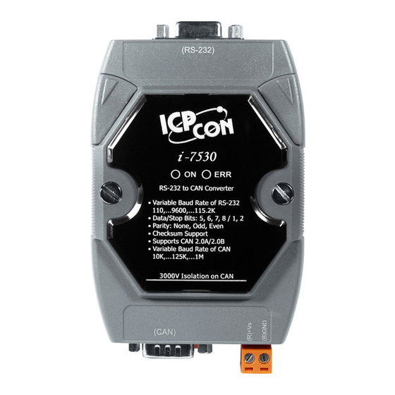
- Page 5 +7(495)109-02-08 sales@bbrc.ru www.bbrc.ru Here are the UART to CAN converters based on the different functionalities. I-7530: The RS-232 to CAN Bus converter with 9-pin D-sub connector. I-7530-FT: The Intelligent RS-232 to low speed fault tolerant CAN Bus converter.
-
Page 6: Common Features Of Can Bus Converter
Provides receive software buffer on CAN and UART side. Allows user-defined CAN baud rate. Supports user-defined end character on pair connection mode. Offers Listen Only Mode. Returns time stamp of the CAN messages. I-7530, I-7530-FT, I-7530A, I-7565 User’s Manual (Version 1.3, Apr/2015) -------- 6... -
Page 7: Specifications Of The Uart To Can Bus Converters
Power reverse polarity protection, Over-voltage brown-out protection Power Consumption 1.5W Mechanism Installation DIN-Rail Dimensions 52mm x 86mm 72mm x 118mm x 33mm (W x L x H) x 32mm I-7530, I-7530-FT, I-7530A, I-7565 User’s Manual (Version 1.3, Apr/2015) -------- 7... - Page 8 7530a-mr.html 3. Users need to Install the USB driver before using I-7565 for the first time. Please refer to Appendix B Install I-7565 Driver I-7530, I-7530-FT, I-7530A, I-7565 User’s Manual (Version 1.3, Apr/2015) -------- 8...
-
Page 9: Pin Assignment
Table: RS-232/485/422 Connector (CN1) Terminal RS-232/485/422 (Y)DATA+ (RS-485) (G)DATA- (RS-485) Tx+ (RS-422) Tx- (RS-422) Rx+ (RS-422) Rx- (RS-422) RXD (RS-232) TXD (RS-232) (B)GND (RS-232) +Vs (10 ~ 30 V Power) (B)GND (Power) I-7530, I-7530-FT, I-7530A, I-7565 User’s Manual (Version 1.3, Apr/2015) -------- 9... - Page 10 CAN GND CAN High The Power/CAN connector for tM-7530: Table: Power / CAN Connector (CN1/CN2) Terminal Power +Vs (10 ~ 30 V Power) GND (Power) F.G. Terminal CAN_L CAN_H CAN_GND I-7530, I-7530-FT, I-7530A, I-7565 User’s Manual (Version 1.3, Apr/2015) -------- 10...
-
Page 11: Block Diagram
The I-7530/I-7530T and tM-7530 provide CAN and RS-232 communication interfaces. The isolator is on the CAN side. The connector of the CAN port to the I-7530/I-7530T and tM-7530 are the D-Sub 9-pin male connector and the spring type connector respectively. - Page 12 The I-7565 provides CAN and USB slave communication interfaces. On the USB interface, the I-7565 provides the virtual COM driver. Users can use the I-7565 instead of the I-7530 if the device only have USB host interface. The I-7565 is powered by the USB interface, it doesn’t need external power.
-
Page 13: Wire Connection
When users use the RS-485 or RS-422 interface, it is strongly recommend to use twisted pair cable for the communication media. Figure: The UART wire connection to the I-7530A I-7530, I-7530-FT, I-7530A, I-7565 User’s Manual (Version 1.3, Apr/2015) -------- 13... - Page 14 ГК Атлант Инжиниринг – официальный представитель в РФ и СНГ +7(495)109-02-08 sales@bbrc.ru www.bbrc.ru The pin assignments of the CAN port (DB9 male) on the I-7530 series including I-7530, I-7530T, I-7530-FT, I-7530A, and I-7565 follows both the CANopen DS102 profile and the appendix C of the DeviceNet specifications.
-
Page 15: Terminator Resistor
Here are the descriptions of how to enable or disable the terminator resistor of the CAN converters. Status JP3 position Enable (default) (Activate) Disable (Deactivate) Status JP4 position Enable (default) (Activate) Disable (Deactivate) I-7530, I-7530-FT, I-7530A, I-7565 User’s Manual (Version 1.3, Apr/2015) -------- 15... - Page 16 There is no terminator resistor in the tM-7530. Therefore, if users would like to use terminator resistor, it is necessary to wire a 120Ω resistance on the CAN bus, as following figure. I-7530, I-7530-FT, I-7530A, I-7565 User’s Manual (Version 1.3, Apr/2015) -------- 16...
-
Page 17: Init/Normal Dip-Switch
DIP-switch of the I-7530/I-7530T, I-7530-FT, I-7530A, and I-7565 are on the back of the module, as following figure. The DIP-switch of the tM-7530 is in the bottom of the module. I-7530, I-7530-FT, I-7530A, I-7565 User’s Manual (Version 1.3, Apr/2015) -------- 17... -
Page 18: Led Indication
“C[CHK]<CR>” to clear the error, or users may need to reboot the CAN converter for recovery. The position and behavior of the LED indicators to the I-7530/I-7530T, I-7530A, and I-7565 is as following figure. I-7530, I-7530-FT, I-7530A, I-7565 User’s Manual (Version 1.3, Apr/2015) -------- 18... - Page 19 CAN Bus Off ERR LED CAN Error Passive Some errors occurred Flash Note: The tM-7530 provides 256 CAN frame FIFO, and 1000 CAN frame FIFO for other CAN converter. I-7530, I-7530-FT, I-7530A, I-7565 User’s Manual (Version 1.3, Apr/2015) -------- 19...
-
Page 20: Software Utility
Note: If users would like to use the old version utility tool of the CAN converter, please refer to the following path. http://ftp.icpdas.com/pub/cd/fieldbus_cd/can/converter/i- 7530/utility/old_version http://ftp.icpdas.com/pub/cd/fieldbus_cd/can/converter/i- 7530a/utility/old_version http://ftp.icpdas.com/pub/cd/fieldbus_cd/can/converter/i- 7565/utility/old_version I-7530, I-7530-FT, I-7530A, I-7565 User’s Manual (Version 1.3, Apr/2015) -------- 20... -
Page 21: How To Configure And Test The Can Converters
PC. Step 4. After finishing the search, the CAN converters (for example tM-7530 and I-7530) which are connecting to the PC or have connected to the PC will be list in the left side of the VxCAN Utility. If the tM-7530 is in Init mode, the VxCAN utility shows the “Init”... - Page 22 * Stop bit: Set the UART stop bit. The CAN converters support 2 kinds of stop bit configuration. * Parity bit: Set the UART parity bit. The CAN converters support 3 kinds of parity bit configuration. I-7530, I-7530-FT, I-7530A, I-7565 User’s Manual (Version 1.3, Apr/2015) -------- 22...
- Page 23 “Required Baud Rate” filed, it means that the required baud rate can’t be reached because of the hardware limitation. The closest baud value will be implemented for instead. I-7530, I-7530-FT, I-7530A, I-7565 User’s Manual (Version 1.3, Apr/2015) -------- 23...
- Page 24 CAN messages by CAN message IDs. About how to calculate the Acceptance Code and the Acceptance Mask, please refer to the Appendix D. I-7530, I-7530-FT, I-7530A, I-7565 User’s Manual (Version 1.3, Apr/2015) -------- 24...
- Page 25 ACK field) to the CAN network. Pair Connection Mode: When uses choose the Pair Connection in the Communication Mode, the pair connection configuration field will presented. I-7530, I-7530-FT, I-7530A, I-7565 User’s Manual (Version 1.3, Apr/2015) -------- 25...
- Page 26 0x0D and 0x0A. When the CAN converter get the UART messages with end characters ‘0x0D’ and ‘0x0A’, it is regarded as the ending of the UART message. The CAN I-7530, I-7530-FT, I-7530A, I-7565 User’s Manual (Version 1.3, Apr/2015) -------- 26...
- Page 27 CAN converter. If users would like to recover the parameters to the factory default, click “Load Default Setting” button to recover all of the configuration parameters to be default value. Afterwards, I-7530, I-7530-FT, I-7530A, I-7565 User’s Manual (Version 1.3, Apr/2015) -------- 27...
- Page 28 Error Response = No TimeStamp Response = No CAN: CAN Specification = 2.0A CAN bus Baud rate = 125K Acceptance Code = 000 Acceptance Mask = 000 Communication: Mode: Normal I-7530, I-7530-FT, I-7530A, I-7565 User’s Manual (Version 1.3, Apr/2015) -------- 28...
- Page 29 Step 3. Click the search button to search all CAN converters connected to the PC. Step 4. Afterwards, the searched CAN modules are listed in the left window of the VxCAN Utility I-7530, I-7530-FT, I-7530A, I-7565 User’s Manual (Version 1.3, Apr/2015) -------- 29...
- Page 30 Send Area Received Area The test interface is divided to two areas. One is for sending CAN messages, and the other is for reception. If users want to send CAN I-7530, I-7530-FT, I-7530A, I-7565 User’s Manual (Version 1.3, Apr/2015) -------- 30...
- Page 31 If the CAN converter gets any CAN messages, they will be shown in received area automatically. About the details for the VxCAN Utility operation please refer to the users’ manual of the VxCAN Utility in the following web site. http://ftp.icpdas.com/pub/cd/fieldbus_cd/can/virtual_can/vxcan_utility/ I-7530, I-7530-FT, I-7530A, I-7565 User’s Manual (Version 1.3, Apr/2015) -------- 31...
-
Page 32: Command List
For easy application, we provide 11 command strings to allow users to send and received commands and responses through the CAN Converter, like I-7530. It can cover most applications of different requests. The general formats of the commands for the CAN Converter modules are in ASCII data format and given below: Command Format: <Command>[CHK]<CR>... - Page 33 1. Sum of the string = ‘R’ + ‘A’ = 52h + 41h = 93h. 2. Therefore the checksum is 93h and so [CHK]=”93”. 3. The command string with checksum =”RA93<CR>”. I-7530, I-7530-FT, I-7530A, I-7565 User’s Manual (Version 1.3, Apr/2015) -------- 33...
-
Page 34: Tiiildd
PC. Example: Command: t03F6112233445566<CR> Send a CAN message with a standard data frame. ID=03F, DLC=6, data1=11, data2=22, data3=33, data4=44, data5=55 and data6=66. I-7530, I-7530-FT, I-7530A, I-7565 User’s Manual (Version 1.3, Apr/2015) -------- 34... -
Page 35: Tiiil[Chk]
CAN Converter Utility, in order to receive Syntax and/or communication error information at the host PC. Example: Command: T2E88<CR> Send a CAN message with a standard remote frame. ID=2E8, DLC=8. I-7530, I-7530-FT, I-7530A, I-7565 User’s Manual (Version 1.3, Apr/2015) -------- 35... -
Page 36: Eiiiiiiiildd
Converter Utility, in order to receive Syntax and/or communication error information at the host PC. Example: Command: e1234567851122334455<CR> Send a CAN message with an extended data frame. ID=12345678, DLC=5, data1=11, data2=22, data3=33, data4=44 and data5=55. I-7530, I-7530-FT, I-7530A, I-7565 User’s Manual (Version 1.3, Apr/2015) -------- 36... -
Page 37: Eiiiiiiiil[Chk]
Converter Utility, in order to receive Syntax and/or communication error information at the host PC. Example: Command: E010156786<CR> Send a CAN message with an extended remote frame. ID=01015678, DLC=6. I-7530, I-7530-FT, I-7530A, I-7565 User’s Manual (Version 1.3, Apr/2015) -------- 37... -
Page 38: S[Chk]
250K baud rate of CAN 500K baud rate of CAN 800K baud rate of CAN 1000K baud rate of CAN 83.3K baud rate of CAN User-defined baud rate of CAN I-7530, I-7530-FT, I-7530A, I-7565 User’s Manual (Version 1.3, Apr/2015) -------- 38... - Page 39 Obtain some current information on the I-7530 module. The response will show the following results: CAN baud rate=250K, CAN register= normal, CAN transmit error counter=0, CAN receive error counter=0 and CAN/RS232 FIFO= normal. I-7530, I-7530-FT, I-7530A, I-7565 User’s Manual (Version 1.3, Apr/2015) -------- 39...
-
Page 40: C[Chk]
It is necessary to enable the “Error Response” function in the CAN Converter Utility, in order to receive Syntax and/or communication error information at the host PC. Example: Command: C<CR> I-7530, I-7530-FT, I-7530A, I-7565 User’s Manual (Version 1.3, Apr/2015) -------- 40... -
Page 41: P0Bbdspae[Chk]
230400 bps baud rate of RS-232, only for I-7565 and tM-7530 460800 bps baud rate of RS-232, only for I-7565 921600 bps baud rate of RS-232, only for I-7565 I-7530, I-7530-FT, I-7530A, I-7565 User’s Manual (Version 1.3, Apr/2015) -------- 41... - Page 42 Set the RS-232/RS-485/RS-422/USB baud rate=115.2K, data bit=8, stop bit=1, none parity, no checksum and No error responses into the CAN Converter module and then reboot the CAN Converter module. I-7530, I-7530-FT, I-7530A, I-7565 User’s Manual (Version 1.3, Apr/2015) -------- 42...
-
Page 43: P1B [Chk]
PC. This command does not support user-defined CAN baud rate function. Example: Command: P14<CR> Set the CAN baud rate=125K into the I-7530 module and then reboot the I-7530 module. I-7530, I-7530-FT, I-7530A, I-7565 User’s Manual (Version 1.3, Apr/2015) -------- 43... -
Page 44: P2Bbdspae[Chk]
19200 bps baud rate of RS-232 38400 bps baud rate of RS-232 57600 bps baud rate of RS-232 115200 bps baud rate of RS-232 230400 bps baud rate of RS-232, only for I-7565 I-7530, I-7530-FT, I-7530A, I-7565 User’s Manual (Version 1.3, Apr/2015) -------- 44... - Page 45 When CAN Converter module was rebooted, the RS-232/RS-485/RS-422/USB parameter will be recovered to the previous setting. I-7530, I-7530-FT, I-7530A, I-7565 User’s Manual (Version 1.3, Apr/2015) -------- 45...
-
Page 46: P3Sbccccccccmmmmmmmm [Chk]
Converter Utility, in order to receive Syntax and/or communication error information at the host PC. This command does not support user-defined CAN baud rate function. About CAN filter setting, please refer to section 3.2. I-7530, I-7530-FT, I-7530A, I-7565 User’s Manual (Version 1.3, Apr/2015) -------- 46... - Page 47 Change the CAN baud rate=125K and acceptance code 0x00000000, acceptance mask 0x00000000 into the CAN Converter module. When CAN Converter module was rebooted, the CAN parameter will be recovered to the previous setting. I-7530, I-7530-FT, I-7530A, I-7565 User’s Manual (Version 1.3, Apr/2015) -------- 47...
-
Page 48: Ra[Chk]
Converter Utility, in order to receive Syntax and/or communication error information at the host PC. Example: Command: RA<CR> The CAN Converter module will reboot after it had received this command. I-7530, I-7530-FT, I-7530A, I-7565 User’s Manual (Version 1.3, Apr/2015) -------- 48... -
Page 49: General Error Code For All Command
The head character of the command string is invalid. The length of the command string is invalid. The checksum of the command string is invalid. Reserved The RS-232/RS-485/RS-422/USB receiver is timeout. I-7530, I-7530-FT, I-7530A, I-7565 User’s Manual (Version 1.3, Apr/2015) -------- 49... -
Page 50: Troubleshooting
In general, the following errors could occur: CAN media connection problem, terminal resistor problem, different baud rate configuration with CAN network and the like. I-7530, I-7530-FT, I-7530A, I-7565 User’s Manual (Version 1.3, Apr/2015) -------- 50... -
Page 51: Appendix A: Cable Selection
(heavier) the wire, the lower the number. For example: a 24AWG wire is thicker/heavier than a 26AWG wire. I-7530, I-7530-FT, I-7530A, I-7565 User’s Manual (Version 1.3, Apr/2015) -------- 51... -
Page 52: Appendix B: Install I-7565 Driver
USB Device. Select to install from a list or specific location. Click Next to continue. 4. An “Install Hardware Device Drivers” window is shown. Click “Next” to initiate a search for a suitable driver for your device. I-7530, I-7530-FT, I-7530A, I-7565 User’s Manual (Version 1.3, Apr/2015) -------- 52... - Page 53 6. If the “Specify a location” is selected, you much choose the correct path. Enter E:\CAN\Converter\I-7565\driver\win2k_xp(The ‘E’ is the Disk that Package CD put in). Click “OK” to start the search. I-7530, I-7530-FT, I-7530A, I-7565 User’s Manual (Version 1.3, Apr/2015) -------- 53...
- Page 54 8. Windows will then install the driver for the USB-to-Serial COM Port. Once installation is complete, Windows will notify you that it has finished installing the software. Click “Finish” to continue. I-7530, I-7530-FT, I-7530A, I-7565 User’s Manual (Version 1.3, Apr/2015) -------- 54...
- Page 55 Ports (COM & LPT). If the device was correctly installed, you should now see the I-756X Converter device listing. This also means that Windows has assigned the device to the COM3 port. I-7530, I-7530-FT, I-7530A, I-7565 User’s Manual (Version 1.3, Apr/2015) -------- 55...
- Page 56 +7(495)109-02-08 sales@bbrc.ru www.bbrc.ru 2. If you need to reassign the virtual COM Port name to another Port number, you can double-click on the device (I-756X Converter) to view the properties. I-7530, I-7530-FT, I-7530A, I-7565 User’s Manual (Version 1.3, Apr/2015) -------- 56...
- Page 57 3. After the uninstall is complete, the program will prompt you to restart Windows. Click “Yes” to continue. 4. Windows will show a dialog box to notify you that the driver was removed successfully. Wait for Windows to restart your computer. I-7530, I-7530-FT, I-7530A, I-7565 User’s Manual (Version 1.3, Apr/2015) -------- 57...
-
Page 58: Appendix C: Can Baud Rate Calculating
“Table: Bit Timing Register”. 4. Bit Timing 3: This parameter is MCU’s bit timing register 3, please refer to the next page “Table: Bit Timing Register”. I-7530, I-7530-FT, I-7530A, I-7565 User’s Manual (Version 1.3, Apr/2015) -------- 58... - Page 59 (20 MHz) / (40 Kbps) = 500. It means that the CAN converter can divided one bit time into 500 parts. The register PRS, PHS1, and PHS2 indicates the numbers of the time slice for T , and T phs1 phs2 I-7530, I-7530-FT, I-7530A, I-7565 User’s Manual (Version 1.3, Apr/2015) -------- 59...
- Page 60 Bit Timing register step by step. 1. Calculate the numbers of the TQ: Numbers of the TQ = (System clock) / (CAN Baud Rate) = 20 M /40 k =500 I-7530, I-7530-FT, I-7530A, I-7565 User’s Manual (Version 1.3, Apr/2015) -------- 60...
- Page 61 Bit Timing 1 register value is 0x30. Bit Timing 2 register value is 0x04. Bit Timing 3 register value is 0x7E. Then, the users can fill those parameter values as below: I-7530, I-7530-FT, I-7530A, I-7565 User’s Manual (Version 1.3, Apr/2015) -------- 61...
- Page 62 2. The function only supports on firmware version 3.00 or more, If the users do not know how to fill those parameter values, please feel free to contact us. I-7530, I-7530-FT, I-7530A, I-7565 User’s Manual (Version 1.3, Apr/2015) -------- 62...
-
Page 63: Appendix D: Filter Setting
CAN 2.0A and CAN 2.0B is the CAN ID bits. In CAN 2.0A: number of CAN ID bits is 11. In CAN 2.0B: number of CAN ID bits is 29. I-7530, I-7530-FT, I-7530A, I-7565 User’s Manual (Version 1.3, Apr/2015) -------- 63... -
Page 64: Appendix E: Pair Connection
RS-232 commands transmitted from one of these two I-7530s will be put in the data field of CAN message. This CAN message will be transferred to RS-232 commands by another I-7530. The following section will show each condition for different pair connection configuration. - Page 65 Communication Descriptions: For example, if there are 7 bytes data, “1234567”, transmitted from Device1 which is sent CAN messages by I-7530#1’s COM port, the Device2 will also receive “1234567” from the COM port of I-7530#2. The CAN ID in above figure is determined by the CAN specification selected by users.
- Page 66 I-7530’s pair connection function. Configurations: To apply this application, user need to configure the CAN Converter module #1 and #2, like I-7530 as above figure. The RS-232 configurations of module #1 and module #2 are decided by the Device1 and Device2 RS-232 parameters.
- Page 67 Configurations: In order to apply this application, user need to configure the three CAN Converter modules #1, #2 and #3, like I-7530 as above figure. The RS-232 configurations of these three CAN Converter modules are decided by the RS-232 device they connect with.
- Page 68 “0021234567” because the Device1 is set to dynamic Tx CAN ID (Fixed Tx CAN ID is not checked). The first three bytes of “0021234567” is “002”, it means that the CAN ID is 0x002 when the I-7530#1 receives the RS- 232 commands from Device1 and transfers it to CAN message.
Need help?
Do you have a question about the I-7530 and is the answer not in the manual?
Questions and answers