Sign In
Upload
Download
Table of Contents
Contents
Add to my manuals
Delete from my manuals
Share
URL of this page:
HTML Link:
Bookmark this page
Add
Manual will be automatically added to "My Manuals"
Print this page
×
Bookmark added
×
Added to my manuals
Manuals
Brands
Teldat Manuals
Network Router
ATLAS 160
Installation manual
Teldat ATLAS 160 Installation Manual
Hide thumbs
1
Table Of Contents
2
3
4
5
6
7
8
9
10
11
12
13
14
15
16
17
18
19
20
21
22
23
page
of
23
Go
/
23
Contents
Table of Contents
Troubleshooting
Bookmarks
Table of Contents
Table of Contents
I - 1. Introduction
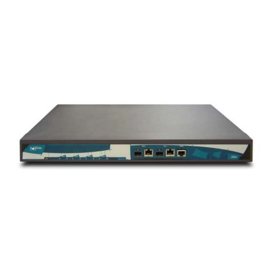
I - 1.1. Device Description
I - 1.2. Recycling and the Environment
I - 2. Connections
I - 2.1. Power Source Connection
I - 2.2. Connections
I - 2.2.1. Interfaces Gigaethernet
I - 2.2.2. Connecting the Antenna
I - 2.2.3. Connecting for Configuration
I - 3. Meaning of the Leds
I - 3.1. ATLAS 160 and 260
I - 3.2. Atlas 360
I - 4. Programming the Microswitches
I - 4.1.1. Procedure to Ignore the Configuration
I - 5. PMC-PCI Cards
I - 5.1. Procedure to Install PMC Cards
I - 6. 16 Port SWITCH Board
II - Chapter. Appendix
Chapter. Appendix
1. Troubleshooting
2. Updating the Software
3. Connectors
3.1. LAN (GE X) Connector
3.2. ANT Connectors
3.3. Configuration Connector
4. Technical Specifications
Configuration Interface
Environmental Specifications
Advertisement
Quick Links
1
I - 1.1. Device Description
2
I - 1. Introduction
3
I - 3.2. Atlas 360
Download this manual
ATLAS X60
Installation Manual
Doc. Dm695-I Ver. 1.0
January, 2008
Table of
Contents
Previous
Page
Next
Page
1
2
3
4
5
Advertisement
Table of Contents
Need help?
Do you have a question about the ATLAS 160 and is the answer not in the manual?
Ask a question
Questions and answers
Subscribe to Our Youtube Channel
Related Manuals for Teldat ATLAS 160
Network Router Teldat ATLAS 360 Installation Manual
(23 pages)
Network Router Teldat ATLAS 150 Installation Manual
(23 pages)
Network Router Teldat Atlas 250 Installation Manual
(32 pages)
Network Router Teldat Atlas 250 Installation Manual
(32 pages)
Network Router Teldat ATLAS 300 Installation Manual
(29 pages)
Network Router Teldat ATLAS 60 NW Installation Manual
Atlas 6x nw series router (38 pages)
Network Router Teldat Atlas-i70 Installation Manual
(32 pages)
Network Router Teldat Edge Router Atlas-840 Installation Manual
(24 pages)
Network Router Teldat C Installation Manual
(29 pages)
Network Router Teldat Teldat-3Ge Quick Manual
Teldat-dm 406-i (33 pages)
Network Router Teldat ATLAS X60 Installation Manual
(23 pages)
Network Router Teldat Teldat-3Ge-USB User Manual
(103 pages)
Network Router Teldat Teldat V Installation Manual
(39 pages)
Network Router Teldat RS123 Seies Installation Manual
(39 pages)
Network Router Teldat M8-Smart Installation Manual
(45 pages)
Network Router Teldat Regesta Smart PRO Manual
(52 pages)
This manual is also suitable for:
Atlas 260
Atlas 360
Table of Contents
Print
Rename the bookmark
Delete bookmark?
Delete from my manuals?
Login
Sign In
OR
Sign in with Facebook
Sign in with Google
Upload manual
Upload from disk
Upload from URL


Need help?
Do you have a question about the ATLAS 160 and is the answer not in the manual?
Questions and answers