
Subscribe to Our Youtube Channel
Related Manuals for Texas Instruments DLP LightCrafter 4500


Summary of Contents for Texas Instruments DLP LightCrafter 4500
- Page 1 LightCrafter 4500™ Evaluation Module ® User's Guide Literature Number: DLPU011E July 2013 – Revised September 2015...
-
Page 2: Table Of Contents
LUT Entry Helper Tool ......................PandaBoard Interface ......................PandaBoard 4500 .............. 6.1.1 DLP LightCrafter 4500 to PandaBoard Interface .................... 6.1.2 PandaBoard Software Contents DLPU011E – July 2013 – Revised September 2015 Submit Documentation Feedback Copyright © 2013–2015, Texas Instruments Incorporated... - Page 3 7.11 JTAG Boundary Scan ........................7.12 Power ..........................Safety ....................Power Supply Requirements ................... External Power Supply Requirements ........................Revision E History DLPU011E – July 2013 – Revised September 2015 Contents Submit Documentation Feedback Copyright © 2013–2015, Texas Instruments Incorporated...
- Page 4 DLP LightCrafter 4500 Connectors (Back-Side View) ................1-9. DLP LightCrafter 4500 Jumper Locations ..............1-10. DLP LightCrafter 4500 J10 and J12 Voltage Jumpers ..............1-11. DLP LightCrafter 4500 J13 and J15 Voltage Jumpers ..................1-12. DLP LightCrafter 4500 Dimensions ................
- Page 5 List of Available Parameters when Saving Solutions ....................5-2. Image LUT Entries Example ............6-1. J1 PandaBoard 4500 to DLP LightCrafter 4500 Interface ............6-2. J3 PandaBoard 4500 to DLP LightCrafter 4500 Interface ............6-3. J4 PandaBoard 4500 to DLP LightCrafter 4500 Interface ............
-
Page 6: Preface
This guide is an introductory document that provides an overview of the DLP LightCrafter 4500 system and its software. Other documents provide more in-depth information of the hardware and software features of the components of the DLP LightCrafter 4500. -
Page 7: Connectors
DLP LightCrafter 4500 Development Platform Forum LightCrafter 4500 is a trademark of Texas Instruments. DLP, Linux are registered trademarks of Texas Instruments. Bluetooth is a registered trademark of Bluetooth SIG, Inc.. Ubuntu is a registered trademark of Canonical Ltd.. - Page 8 If You Need Assistance www.ti.com Read This First DLPU011E – July 2013 – Revised September 2015 Submit Documentation Feedback Copyright © 2013–2015, Texas Instruments Incorporated...
-
Page 9: Dlp Lightcrafter 4500 Module Overview
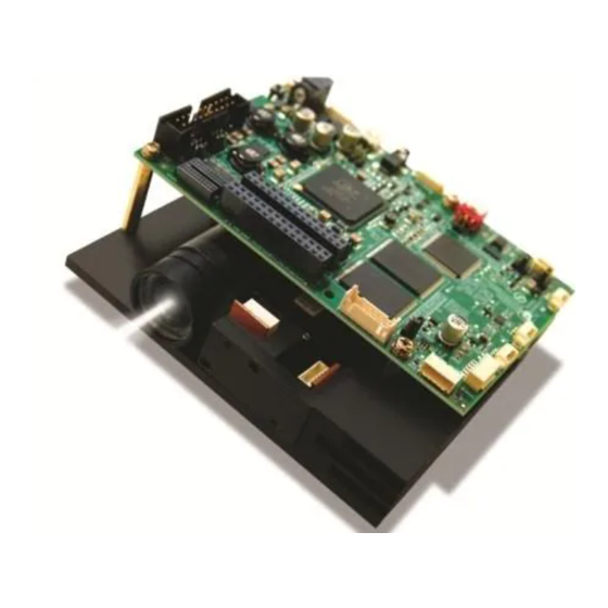
DLPU011E – July 2013 – Revised September 2015 DLP LightCrafter 4500 Module Overview Welcome The DLP LightCrafter 4500 evaluation module (EVM) allows evaluation of the DLP 4500 platform from TI. This technology brings together a set of components providing an efficient and compelling system solution for: •... -
Page 10: Light Engine
What is in the LightCrafter 4500 EVM? www.ti.com Figure 1-1. DLP LightCrafter 4500 Block Diagram 1.2.1 Light Engine iView Limited developed the IPD 1231 light engine for the DLP LightCrafter 4500. As shown in Figure 1-2, the light engine includes: •... -
Page 11: Iview Light Engine
When every other row or column is used, a more faint line is projected. DLPU011E – July 2013 – Revised September 2015 DLP LightCrafter 4500 Module Overview Submit Documentation Feedback Copyright © 2013–2015, Texas Instruments Incorporated... -
Page 12: Inch Dmd Diamond Pixel Geometry
Figure 1-5. Diamond Pixel for Vertical, Horizontal, and Diagonal Lines 1.2.1.1 Light Engine Thermal Limits The DLP LightCrafter 4500 is an actively cooled system with a thermal limit requiring that of all three simultaneous LED currents is less than 4.3 A. CAUTION Do not overheat the system by driving all LEDs at maximum power. -
Page 13: Driver Board
1.2.2 Driver Board The DLP LightCrafter 4500 driver board contains the electronics to drive the DLP4500 DMD, LEDs of the light engine, and the LED cooling fan. The driver board offers several interface options for USB, I trigger inputs and outputs, video input through mini-HDMI and FPD-link connector, and a system board interface. -
Page 14: Embedded Processor Interface
Chapter Other Items Needed for Operation The DLP LightCrafter 4500 module is a flexible, ready-to-use EVM. However, the DLP LightCrafter 4500 EVM does not ship with cables, power supply, or additional hardware components. To use the EVM, the user needs the following: •... -
Page 15: Dlp Lightcrafter 4500 Connections
J28 for 3.3-V or 1.8-V supply. Then use this connector to control an external LED driver board to power the LEDs of the DLP LightCrafter 4500 light engine or external light engine. 16. System board connector: This interface routes USB, I C, GPIO, and triggers from DLPC350 to a system board to control the DLP LightCrafter 4500. -
Page 16: Dlp Lightcrafter 4500 Connectors (Top View)
DLP LightCrafter 4500 Connections www.ti.com Figure 1-7. DLP LightCrafter 4500 Connectors (Top View) Figure 1-8. DLP LightCrafter 4500 Connectors (Back-Side View) DLP LightCrafter 4500 Module Overview DLPU011E – July 2013 – Revised September 2015 Submit Documentation Feedback Copyright © 2013–2015, Texas Instruments Incorporated... -
Page 17: Dlp Lightcrafter 4500 Jumpers
DLP LightCrafter 4500 Jumpers The DLP LightCrafter 4500 has jumper options to disable the onboard LED driver, control voltages of the LED signals to an external board, and control the trigger input and output voltages. This section lists all the jumpers on the DLP LightCrafter 4500 driver board. -
Page 18: Dlp Lightcrafter 4500 J10 And J12 Voltage Jumpers
DLP LightCrafter 4500 Jumpers www.ti.com Figure 1-10. DLP LightCrafter 4500 J10 and J12 Voltage Jumpers • J13: DLPC350 TRIG1_OUT voltage selection. See to Figure 1-11. – Jump across pins 3 to 4 for 3.3 V – Jump across pins 5 to 6 for 1.8 V •... -
Page 19: Dimensions
The dimensions of the DLP LightCrafter 4500 are of 98 mm long, 121.6 mm wide, and 47.7 mm tall. -
Page 20: Dlp Lightcrafter 4500 Dimensions
Dimensions www.ti.com Figure 1-12. DLP LightCrafter 4500 Dimensions DLP LightCrafter 4500 Module Overview DLPU011E – July 2013 – Revised September 2015 Submit Documentation Feedback Copyright © 2013–2015, Texas Instruments Incorporated... - Page 21 Dimensions www.ti.com DLPU011E – July 2013 – Revised September 2015 DLP LightCrafter 4500 Module Overview Submit Documentation Feedback Copyright © 2013–2015, Texas Instruments Incorporated...
-
Page 22: Quick Start
4. Control the DLP LightCrafter 4500 with the free GUI software (available to download from http://www.ti.com/dlplightcrafter4500). 5. After installing the software on the computer, connect the PC to the DLP LightCrafter 4500 using a USB to mini-USB cable (connector 4 in Figure 1-8). - Page 23 Power-up the DLP LightCrafter 4500 www.ti.com DLPU011E – July 2013 – Revised September 2015 Quick Start Submit Documentation Feedback Copyright © 2013–2015, Texas Instruments Incorporated...
-
Page 24: Operating The Dlp Lightcrafter 4500
This chapter introduces the PC software provided with the DLP LightCrafter 4500. DLP LightCrafter 4500 Software The DLP LightCrafter 4500 includes a QT-based GUI application to control the module through the USB interface. QT is a Nokia cross-platform application and user-interface framework with open source and commercial licenses. -
Page 25: System Status
Figure 3-1. DLP LightCrafter 4500 GUI – Video Mode The DLP LightCrafter 4500 GUI communicates with the DLPC350 using USB 1.1. The DLPC350 emulates as a USB device with HID support. The PC polls all the HID peripherals and once the PC detects the DLPC350, the Connected button changes to green. -
Page 26: Operating Mode
When highlighted gray, no buffer swap error has occurred. This error can occur if the DLP LightCrafter 4500 is set to Video Mode and the vertical backporch timing is too small. The error can also occur if the DLP LightCrafter 4500 is set to Pattern Sequence mode with patterns input from the video port and pattern sequence timings do not match the video port VSYNC. -
Page 27: Image Orientation
Beneath Operating Mode, the Image Orientation controls the long and short axis flips to support front, rear, table, and ceiling mounted projection. The Image Orientation occurs on the next image or frame load in Video mode, and on the next download to the DLP LightCrafter 4500 in Pattern Sequence mode. •... -
Page 28: Led Current Settings
Figure 4. Typical Blue LED Current and Illuminance Based on PWM Values CAUTION The DLP LightCrafter 4500 is an actively cooled system that has a thermal limit resulting in total simultaneous red, green, and blue LED currents less than 4.3 A for continuous LED operation. Do not overheat the system by turning all LEDs at maximum power during prolonged and simultaneous LED use. -
Page 29: Video Mode
LED of that color at the given LED current setting. 3.2.5 Video Mode When the DLP LightCrafter 4500 is configured in Video Mode, the Input Source Select section in Figure 3- in the top-left part of the Video Mode tab selects the input source to be displayed by the DLPC350. The DLPC350 treats these as video inputs and applies image processing functions, like scaling, gamma correction, color coordinate adjustments, and so forth. -
Page 30: Pattern Sequence Mode
Pattern Sequence Mode When the DLP LightCrafter 4500 is configured in Pattern Sequence mode, the DLPC350 supports 1-, 2-, 3-, 4-, 5-, 6-, 7-, and 8-bit images with a 912 columns × 1140 rows resolution. These images are pixel accurate, meaning that each pixel corresponds to a micromirror on the DMD and is not processed by any of the video processing functions. -
Page 31: Dlp Lightcrafter 4500 Gui - Pattern Sequence Mode
DLP LightCrafter 4500 during Pattern Sequence mode. To synchronize a camera or external system with the displayed patterns, the DLP LightCrafter 4500 supports a set of trigger inputs and outputs. These inputs and outputs are configured through the Trigger Mode section and Trigger Controls subtab. - Page 32 (e) If a black image is desired between patterns, check the Clear DMD after exposure. (f) Click the Add Pattern to Sequence button. (g) Repeat Steps through for each pattern in the sequence. Operating the DLP LightCrafter 4500 DLPU011E – July 2013 – Revised September 2015 Submit Documentation Feedback...
- Page 33 6. Clicking the Validate Sequence button executes a data validation and updates the Data Validation status indicators in this tab. If the data validates successfully, the pattern sequence is downloaded to the DLP LightCrafter 4500 and waits for the Play button to be pressed to start displaying the pattern sequence.
-
Page 34: Pattern Sequence Mode: Start, Pause, Stop
For each 24 bit-plane of the packed 24-bit RGB image, select one bit-plane (a monochrome image) and add it to the pattern sequence by: Operating the DLP LightCrafter 4500 DLPU011E – July 2013 – Revised September 2015 Submit Documentation Feedback... -
Page 35: Sequence Settings [Variable Exposure]
• This forms 24 1-bit images that are displayed back-to-back at 100-ms exposure. Click on the Send button to download the pattern sequence to the DLP LightCrafter 4500. 3.3.2 Sequence Settings [Variable Exposure] When operating in Pattern Sequence [Variable Exposure] mode, use this subtab to set the sequence settings. -
Page 36: Image Load Timing
The DLPC350 decompresses the 24-bit RGB bitmap stored at the Image Index location and loads it to the internal buffer. The time required for this process is displayed in milliseconds. This feature overwrites the images currently in the display buffer. Operating the DLP LightCrafter 4500 DLPU011E – July 2013 – Revised September 2015 Submit Documentation Feedback... -
Page 37: Trigger Controls
0 µs and 28084.95 µs, but for more information on how to extend the delay range, see the DLPC350 Programmer's Guide DLPU010 • TRIG_OUT_1: DLPU011E – July 2013 – Revised September 2015 Operating the DLP LightCrafter 4500 Submit Documentation Feedback Copyright © 2013–2015, Texas Instruments Incorporated... -
Page 38: Trigger Control Subtab
– Trigger 2 Patterns per Pulse: Indicates the number of patterns per TRIG_OUT_2 pulse. Figure 3-9. Trigger Control Subtab The trigger output signals are: Operating the DLP LightCrafter 4500 DLPU011E – July 2013 – Revised September 2015 Submit Documentation Feedback... -
Page 39: Led Delay Control
LED enable signals can be independently changed between –20.05 µs (before pattern exposure) to +7.29 µs (after pattern exposure) delay. When the DLP LightCrafter 4500 is operating in Video Mode, set these delays to 0 (–20.05 µs). DLPU011E – July 2013 – Revised September 2015... -
Page 40: Firmware Upgrade
Figure 3-12. LED Delay Control Subtab Firmware Upgrade The DLP LightCrafter 4500 GUI allows field updates of the DLPC350 firmware. To update the DLPC350 firmware, perform the following steps Figure 3-13 1. Select the Image / Firmware tab and the Firmware Upload subtab. -
Page 41: Storing Images In Flash Memory
(b) Click the Add to Output File button. The current image is bit weighted and saved into the 24-bit image of the output file. DLPU011E – July 2013 – Revised September 2015 Operating the DLP LightCrafter 4500 Submit Documentation Feedback Copyright © 2013–2015, Texas Instruments Incorporated... -
Page 42: Create Images Tab
File button on the bottom left above the Save Updates button to select an existing INI file. Otherwise, leaving this field blank will bundle the Default.ini file in the GUI top level directory with this firmware build Operating the DLP LightCrafter 4500 DLPU011E – July 2013 – Revised September 2015 Submit Documentation Feedback... -
Page 43: Firmware Builder
24-bit images. Figure 3-15. Firmware Builder DLPU011E – July 2013 – Revised September 2015 Operating the DLP LightCrafter 4500 Submit Documentation Feedback Copyright © 2013–2015, Texas Instruments Incorporated... -
Page 44: Peripheral Control
<value><space><value><space>... For example: 0x22 0x11. The number for bytes to be read is input as a decimal value. Figure 3-16. Peripheral Control Tab Operating the DLP LightCrafter 4500 DLPU011E – July 2013 – Revised September 2015 Submit Documentation Feedback... - Page 45 Peripheral Control www.ti.com DLPU011E – July 2013 – Revised September 2015 Operating the DLP LightCrafter 4500 Submit Documentation Feedback Copyright © 2013–2015, Texas Instruments Incorporated...
-
Page 46: Pattern Sequences
DLPU011E – July 2013 – Revised September 2015 Pattern Sequences This chapter describes the pattern sequences supported by the DLP LightCrafter 4500 module. Pattern Sequence Background The DLPC350 takes as input 24-, 27-, or 30-bit RGB data at a frame rate of up to 120-Hz. This frame rate is composed of three colors (red, green, and blue) with each color equally divided in the 120-Hz frame rate. -
Page 47: Dlpc350 Internal Memory Buffer
RGB parallel or FPD-link interface. Figure 4-3. DLPC350 Internal Memory Buffer When the DLP LightCrafter 4500 is set to Video Mode, the displayed image is a frame delayed in relation to the data streamed through the RGB parallel interface or FPD-link, as shown in Figure 4-4. -
Page 48: Frame Delay Between Parallel Interface Input And Projection Output
Figure 4-4. Frame Delay Between Parallel Interface Input and Projection Output When the DLP LightCrafter 4500 is set to Pattern Sequence mode with pattern source from flash, the pattern sequence must be loaded from flash memory. The DLPC350 takes at-worst-case 200 ms to load one buffer (24 bit-planes). -
Page 49: Allowable Pattern Combinations
2 bits 1428 1428 3 bits 1570 4 bits 1700 5 bits 2000 6 bits 2500 7 bits 4500 8 bits 8333 DLPU011E – July 2013 – Revised September 2015 Pattern Sequences Submit Documentation Feedback Copyright © 2013–2015, Texas Instruments Incorporated... - Page 50 Pattern Sequence Background www.ti.com Pattern Sequences DLPU011E – July 2013 – Revised September 2015 Submit Documentation Feedback Copyright © 2013–2015, Texas Instruments Incorporated...
-
Page 51: Saving Solutions
GUI. The second method is to open the .ini file in a text file editor and edit it manually. 5.3.1 Available Parameters Table 5-1 lists all available parameters. For more details read the Programmer’s Guide (DLPU010). DLPU011E – July 2013 – Revised September 2015 Saving Solutions Submit Documentation Feedback Copyright © 2013–2015, Texas Instruments Incorporated... -
Page 52: List Of Available Parameters When Saving Solutions
Must be less than 128 (where 0x0 = 1, and 0x7F = ENTRIES 128). Must equal number of items in DEFAULT.SEQPATLUT. Saving Solutions DLPU011E – July 2013 – Revised September 2015 Submit Documentation Feedback Copyright © 2013–2015, Texas Instruments Incorporated... -
Page 53: Save Solution Button
GUI. Select which value or values you want in your .ini file. This method is the preferred way of previewing syntax errors or invalid entries. DLPU011E – July 2013 – Revised September 2015 Saving Solutions Submit Documentation Feedback Copyright © 2013–2015, Texas Instruments Incorporated... -
Page 54: Manual Editing
12, 0, 13, 12, 1, 13, 12, and so on. Table 5-2. Image LUT Entries Example SL No. Image Index in Decimal DEFAULT.SPLASHLUT Saving Solutions DLPU011E – July 2013 – Revised September 2015 Submit Documentation Feedback Copyright © 2013–2015, Texas Instruments Incorporated... - Page 55 Modifying .ini Files www.ti.com DLPU011E – July 2013 – Revised September 2015 Saving Solutions Submit Documentation Feedback Copyright © 2013–2015, Texas Instruments Incorporated...
-
Page 56: Pandaboard Interface
• HDMI output and a camera input connector. The combination of PandaBoard ES with DLP LightCrafter 4500 allows for the creation of self-contained, high-precision mobile tools to meet a growing number of applications, such as inline machine vision systems, portable, high-accuracy 3D scanners, and field spectrometers. -
Page 57: Dlp Lightcrafter 4500 To Pandaboard Interface
6-2, the DLP LightCrafter 4500 supplies 5-V power to the PandaBoard. The PandaBoard provides 1.8 V to the DLP LightCrafter 4500 to level-shift all the signals interfacing the two boards together. The following OMAP4 GPIOs control the routing of OMAP4 peripherals to the corresponding DLPC350 peripherals: •... -
Page 58: Block Diagram Of The Pandaboard Interface
PandaBoard 4500 www.ti.com Figure 6-2. Block Diagram of the PandaBoard Interface Table 6-1. J1 PandaBoard 4500 to DLP LightCrafter 4500 Interface PandaBoard 4500 J1 DLP LightCrafter 4500 J1 Signal Description Signal Description DCIN_JACK 5 V supplied from DLP LightCrafter 4500... -
Page 59: J3 Pandaboard 4500 To Dlp Lightcrafter 4500 Interface
PandaBoard 4500 www.ti.com Table 6-2. J3 PandaBoard 4500 to DLP LightCrafter 4500 Interface PandaBoard 4500 J3 DLP LightCrafter 4500 J3 Signal Description Signal Description VIO_1V8 Panda 1.8-V system I/O voltage EXT_1V8 1.8 V supplied by Panda 5 V supplied from DLP... -
Page 60: J4 Pandaboard 4500 To Dlp Lightcrafter 4500 Interface
PandaBoard 4500 www.ti.com Table 6-3. J4 PandaBoard 4500 to DLP LightCrafter 4500 Interface PandaBoard 4500 J4 DLP LightCrafter 4500 J4 Signal Description Signal Description Panda power rail VDD_V AUX2 No connect (adjustable from 1.2 V to 2.8 V) VIO_1V8 Panda 1.8 V system I/O voltage EXT_1V8 1.8 V supplied by Panda... -
Page 61: Pandaboard Software
Note: Only up to revision B2 of the PandaBoard are officially supported The HDMI connector is the default display output of PandaBoard. To reroute the display video output to the RGB interface of the DLP LightCrafter 4500, the kenrel config file must be modified with the following changes: •... - Page 62 Set the DVI as the default output by adding the following entry to boot.scr: – omapfb.mode=dvi omapdss.def_disp=dvi • Set the desired resolution fro the DLP LightCrafter 4500 output by adding one of the following entries to boot.scr: – omapfb.mode=dvi:912x1140MR-24@60 – omapfb.mode=dvi:1280x800MR-24@60 •...
- Page 63 PandaBoard 4500 www.ti.com DLPU011E – July 2013 – Revised September 2015 PandaBoard Interface Submit Documentation Feedback Copyright © 2013–2015, Texas Instruments Incorporated...
-
Page 64: Input Trigger Connector Pins
DLPU011E – July 2013 – Revised September 2015 Connectors This chapter describes the connector pins of the DLP LightCrafter 4500 module. Input Trigger Connectors Table 7-1 lists the input trigger connector (J11) pins. The trigger inputs have hysteresis. Two matching six- pin, 1.25-mm connector part numbers are:... -
Page 65: Uart Connector Pins
Table 7-5. I C1 Connector Pins Description Supply Range C SCL 3.3 V C SDA 3.3 V 3.3-V supply 3.3 V Ground DLPU011E – July 2013 – Revised September 2015 Connectors Submit Documentation Feedback Copyright © 2013–2015, Texas Instruments Incorporated... -
Page 66: Fan Connector Pins
• Digi-Key part number: WM2093-ND The corresponding terminal (crimp) part numbers are: • Molex part number: 87421-0000 • Digi-Key part number: WM1112-ND Connectors DLPU011E – July 2013 – Revised September 2015 Submit Documentation Feedback Copyright © 2013–2015, Texas Instruments Incorporated... -
Page 67: Green Led Connector Pins
1.2 V RXE_AN 1.2 V RXE_BP 1.2 V RXE_CP 1.2 V Ground Ground RXE_BN 1.2 V RXE_CN 1.2 V RXE_DP 1.2 V DLPU011E – July 2013 – Revised September 2015 Connectors Submit Documentation Feedback Copyright © 2013–2015, Texas Instruments Incorporated... -
Page 68: Jtag Boundary Scan Connector Pins
Switchcraft part number: 760 • Digi-Key part number: SC1051-ND Table 7-12. Power Connector Pins Description Supply Range Input supply 12 V Ground Ground Connectors DLPU011E – July 2013 – Revised September 2015 Submit Documentation Feedback Copyright © 2013–2015, Texas Instruments Incorporated... - Page 69 Power www.ti.com DLPU011E – July 2013 – Revised September 2015 Connectors Submit Documentation Feedback Copyright © 2013–2015, Texas Instruments Incorporated...
- Page 70 CAUTION To minimize the risk of fire or equipment damage, make sure that air is allowed to circulate freely around the DLP LightCrafter 4500 board when operating. CAUTION The kit contains ESD-sensitive components. Handle with care to prevent permanent damage.
- Page 71 Appendix A www.ti.com DLPU011E – July 2013 – Revised September 2015 Safety Submit Documentation Feedback Copyright © 2013–2015, Texas Instruments Incorporated...
-
Page 72: Power Supply Requirements
Appendix B DLPU011E – July 2013 – Revised September 2015 Power Supply Requirements External Power Supply Requirements The DLP LightCrafter 4500 does not include a power supply. The external power supply requirements are: • Nominal voltage: 12-V DC • Minimum current: 0 A •... - Page 73 External Power Supply Requirements www.ti.com DLPU011E – July 2013 – Revised September 2015 Power Supply Requirements Submit Documentation Feedback Copyright © 2013–2015, Texas Instruments Incorporated...
- Page 74 ......................• Added Firmware Builder figure NOTE: Page numbers for previous revisions may differ from page numbers in the current version. Revision History DLPU011E – July 2013 – Revised September 2015 Submit Documentation Feedback Copyright © 2013–2015, Texas Instruments Incorporated...
-
Page 75: Important Notice
IMPORTANT NOTICE Texas Instruments Incorporated and its subsidiaries (TI) reserve the right to make corrections, enhancements, improvements and other changes to its semiconductor products and services per JESD46, latest issue, and to discontinue any product or service per JESD48, latest issue. - Page 76 Mouser Electronics Authorized Distributor Click to View Pricing, Inventory, Delivery & Lifecycle Information: Texas Instruments DLPLCR4500EVM...
Need help?
Do you have a question about the DLP LightCrafter 4500 and is the answer not in the manual?
Questions and answers