
Related Manuals for Texas Instruments DLP LightCrafter


Summary of Contents for Texas Instruments DLP LightCrafter
- Page 1 LightCrafter™ Evaluation Module (EVM) ® User's Guide Literature Number: DLPU006C January 2012 – Revised December 2013...
-
Page 2: Table Of Contents
2.2.4 Fixing the USB Start-Up Delay in Windows ..............2.2.5 Changing the DLP LightCrafter's IP Address ............2.2.6 Connecting Multiple DLP LightCrafter's to One PC ....................Selecting the Display Mode ....................Setting the LED Current .................... Controlling Image Orientation ............. - Page 3 2.14 Changing the Splash Screens ............2.15 Loading Images from the SD Card with Slide Show Mode .................. Developing with the DLP LightCrafter ................... Compiling the GUI Using QT Creator ............Compiling the MSP430 Firmware Using Code Composer ..................Developing with the TI DVSDK ......................
- Page 4 2-32. DLP LightCrafter GUI Output Trigger Enable Checkbox ..............2-33. DLP LightCrafter GUI Output Trigger Set Button ........2-34. DLP LightCrafter GUI RGB Video Streaming Selected on HDMI Port Tab ............2-35. DLP LightCrafter GUI RGB Video Streaming Set Button .........
- Page 5 ................2-44. MBMC Pattern Sequence Output Example 2-45. DLP LightCrafter GUI Multiple Bit and Multiple Color Sequence Settings Tab in Stored Pattern Sequence .......................... 2-46. DLP LightCrafter GUI Multiple Bit and Multiple Color Sequence Settings Tab in Stored Pattern Sequence ..........................
- Page 6 List of Tables ................. 1-1. DLP LightCrafter Light Engine Specifications ................ 1-2. DLP LightCrafter Protection Shutdown Modes ..................... 2-1. LED Current Settings ................. 2-2. Supported Resolutions for Video Input ................2-3. MBMC Pattern Sequence Information Input ................4-1. Allowable External Pattern Combinations ..................
-
Page 7: Preface
This guide is an introductory document for the DLP LightCrafter that provides an overview of the system and its software. Other documents provide more in-depth information of the hardware and software features of the components of the DLP LightCrafter. -
Page 8: Dlp ® Lightcrafter™ Module Overview
This chapter introduces the DLP LightCrafter module. Welcome Your new DLP LightCrafter module allows you to evaluate TI’s DLP 0.3-inch WVGA chipset platform along with TI’s DaVinci Technology and the DM365 architecture. This technology brings together a set of components providing an efficient and compelling system solution for: •... -
Page 9: Light Engine
What is in the LightCrafter EVM? www.ti.com Figure 1-1. DLP LightCrafter Block Diagram 1.2.1 Light Engine Young Optics, Inc. developed the DLP LightCrafter’s light engine. The light engine consists of the following components: • 0.3-inch WVGA DMD (DLP3000) • OSRAM Red LED (LE A Q9WN) •... -
Page 10: Driver Board
Table 2-1 for the corresponding LED current software settings. 1.2.2 Driver Board Figure 1-3 shows the DLP LightCrafter’s driver board block diagram. ® LightCrafter™ Module Overview DLPU006C – January 2012 – Revised December 2013 Submit Documentation Feedback Copyright © 2012–2013, Texas Instruments Incorporated... -
Page 11: Dlp Lightcrafter Driver Board Block Diagram
What is in the LightCrafter EVM? www.ti.com Figure 1-3. DLP LightCrafter Driver Board Block Diagram The major components of the DLP LightCrafter’s driver board are: • DLP3000: 0.3-inch WVGA chipset DMD • DLPC300: 0.3-inch WVGA chipset controller for DLP3000 with: –... -
Page 12: System Board
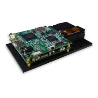
1.2.3 System Board Figure 1-4 shows the DLP LightCrafter’s system board. Figure 1-4. DLP LightCrafter System Board Block Diagram The major components of the system board are: • Altera Cyclone IV FPGA: – Controls video muxing (external miniHDMI or DM365) –... -
Page 13: Dlp Lightcrafter Embedded Software Overview
Figure 1-5. DM365 DVSDK Software Platform Out of the box, the DLP LightCrafter boots from the on-board NAND FLASH. The DM365 acts as the main processor of the system and boots as an embedded Linux device. The Linux file system resides on the NAND or micro-SD card. -
Page 14: Msp430 Overview And Shutdown Protection Modes
– DM365 YUV4:2:2 video converted to RGB888 (bit identical with stored patterns). • Timing and signal management for a "circular" frame buffer. Please read the DLP LightCrafter FPGA Overview application note for more details. TI literature number DLPA042 Figure 1-6 shows the block diagram of the FPGA hardware. -
Page 15: Other Items Needed For Operation
Other Items Needed for Operation www.ti.com Other Items Needed for Operation The DLP LightCrafter module is a flexible, ready to use EVM. However, DLP LightCrafter EVM does not ship with any cables, power supply, or additional hardware components. To use the EVM, you need: •... -
Page 16: Dlp Lightcrafter's Dimensions
Figure 1-7. DLP LightCrafter Connector Locations DLP LightCrafter's Dimensions The DLP LightCrafter optical engine is mounted on top of a thermal plate to provide passive cooling to the module. The DLP3000, 0.3-inch DMD, is vertically mounted at the end of the optical engine and attached with a connector to the driver board. -
Page 17: Dlp Lightcrafter Module Dimensions
DLP LightCrafter's Dimensions www.ti.com Figure 1-8. DLP LightCrafter Module Dimensions DLPU006C – January 2012 – Revised December 2013 ® LightCrafter™ Module Overview Submit Documentation Feedback Copyright © 2012–2013, Texas Instruments Incorporated... -
Page 18: Operating The Dlp Lightcrafter
DLP LightCrafter GUI v5.0. Installing the GUI DLP LightCrafter includes a QT-based GUI to control the module through USB. QT is a Nokia cross- platform application and user interface framework with open source and commercial licenses. To install the DLP LightCrafter GUI, follow these steps. -
Page 19: Dlp Lightcrafter Gui Connect Button
Connecting to a PC www.ti.com 2. Turn on DLP LightCrafter using the On-Off switch. A new network using the RNDIS driver should initialize. • The network interface on Windows systems may take a couple minutes to initialize. Please read Section 2.2.4 to speed up the initialization. -
Page 20: Installing The Rndis Driver On Windows Xp
2.2.2 Installing the RNDIS Driver on Windows 7 The first time DLP LightCrafter is connected on Windows 7 systems a pop-up window appears stating that a new hardware device called a "RNDIS/Ethernet Gadget" was found. Follow these steps to install the "RNDIS/Ethernet Gadget"... -
Page 21: Windows 7 Driver Software Installation Window
Figure 2-6. Windows 7 Device Manager Window 4. Select “Browse my computer for driver software” from the “Update Driver Software” window. See Figure 2-7. DLPU006C – January 2012 – Revised December 2013 Operating the DLP LightCrafter Submit Documentation Feedback Copyright © 2012–2013, Texas Instruments Incorporated... -
Page 22: Windows 7 Update Driver Software Search Or Browse Window
7. Select "Microsoft Corporation" as the manufacturer and “Remote NDIS Compatible Device” as the network adapter. Click "Next." See Figure 2-9. Operating the DLP LightCrafter DLPU006C – January 2012 – Revised December 2013 Submit Documentation Feedback Copyright © 2012–2013, Texas Instruments Incorporated... -
Page 23: Enabling The Rndis Driver On Linux
Figure 2-10. Windows 7 Update Driver Software Successfully Updated Window 2.2.3 Enabling the RNDIS Driver on Linux DLP LightCrafter connects to Linux systems as a Linux-USB Ethernet/RNDIS device. Some systems require USB networking support to be manually enabled. To enable USB networking follow these steps: 1. -
Page 24: Ubuntu Command Terminal And "Interfaces" File
Choose an IP address different than the address of the LightCrafter. 7. Check that usb0 was properly assigned an IP address using "ifconfig." See Figure 2-13. Operating the DLP LightCrafter DLPU006C – January 2012 – Revised December 2013 Submit Documentation Feedback Copyright © 2012–2013, Texas Instruments Incorporated... -
Page 25: Fixing The Usb Start-Up Delay In Windows
IP address. This "Identifying..." process for the Local Area Connection can take over a minute on some systems. To decrease the time required for DLP LightCrafter to connect, the Local Area Network assigned an IP address allowing the computer to connect to the EVM within seconds after fully booting. -
Page 26: Windows 7 Network Connections Identifying Local Area Connection
2-16. Figure 2-16. Windows 7 Command Window Local Area Connection IPv4 Address 8. From the Network Connections window, right click on DLP LightCrafter's Local Area Connection and click "Properties" 9. In the box "This connection uses the following items" under the Networking tab, look for “Internet Protocol Version 4”. -
Page 27: Changing The Dlp Lightcrafter's Ip Address
12. Click "OK" to exit the IPv4 Properties 13. Click "OK" to exit the LAN connection properties. 2.2.5 Changing the DLP LightCrafter's IP Address To change DLP LightCrafter's IP address, follow these steps: 1. Connect DLP LightCrafter GUI to EVM. 2. Select the "Connections" tab. See Figure 2-19. -
Page 28: Connecting Multiple Dlp Lightcrafter's To One Pc
IP addresses for the connected EVM. 3. Disconnect and turn off the EVM. 4. Repeat steps 1-3 for each DLP LightCrafter. 5. After all DLP LightCrafter's have unique IP addresses, start an instance of the DLP LightCrafter GUI for each EVM •... -
Page 29: Selecting The Display Mode
Selecting the Display Mode www.ti.com Selecting the Display Mode The DLP LightCrafter has four display modes: Static Image/Color, Test Patterns, HDMI Port, and Stored Pattern Sequence. To upload static 24-bit RGB images or project a single color read section Section 2.9. -
Page 30: Setting The Led Current
When at room temperature, the maximum value allowed is dependent on the cooling system of the DLP LightCrafter. The passively cooled systems of the DLP LightCrafter (no extra heat sinks or fans) have a thermal limit resulting in LED currents under 633 mA. DLP LightCrafter actively cooled systems (extra heat sink and fan) have a thermal limit resulting in LED currents under 1.5 A. -
Page 31: Controlling Image Orientation
See Figure 2-27. Figure 2-27. DLP LightCrafter GUI LED Current Setting Active Cooling Needed • If the value is above 758, the value turns red and a note is added to the LED Current title to inform the user that this is not a recommended setting. -
Page 32: Triggering External Peripherals (Camera And So Forth)
Triggering External Peripherals (Camera and So Forth) The DLP LightCrafter features a trigger output on connecter J7 to allow cameras and other peripherals to be in sync with the EVM. The trigger output is an open drain type with a 10 kΩ internal pull-up resistor. -
Page 33: Dlp Lightcrafter Gui Output Trigger Settings
The output trigger can only be enabled if the EVM is in either "Stored Pattern Sequence" mode or "External Streaming Pattern Sequence" while in "HDMI Port" mode. Figure 2-32. DLP LightCrafter GUI Output Trigger Enable Checkbox 2. If an active low trigger output is desired, check the "Invert" checkbox. If an active high trigger output is desired do not check "Invert"... -
Page 34: Streaming 24-Bit Rgb Video From The Hdmi Port
5. To retrieve DLP LightCrafter's current output trigger settings, click the "Get" button Streaming 24-bit RGB Video from the HDMI Port DLP LightCrafter can operate as a DVI-D compliant projector with its mini-HDMI connector. By default, the EVM has the 608 x 684 EDID software installed, and supports resolutions listed in Table 2-2. -
Page 35: Creating Pattern Sequences
8. To retrieve the EVM's current video mode settings, click the "Get" button. Creating Pattern Sequences The DLP LightCrafter can perform external and internal pattern sequences. External sequences use streaming patterns from the mini-HDMI port. Internal sequences use preloaded patterns and can be stored on the LightCrafter with solutions for reuse. -
Page 36: Dlp Lightcrafter Gui Sequence Settings Tab In Stored Pattern Sequence Tab
Creating Pattern Sequences www.ti.com Figure 2-36. DLP LightCrafter GUI Sequence Settings Tab in Stored Pattern Sequence Tab 3. Set Pattern settings by updating the following parameters inside the Pattern Setting box: • Bit Depth: bit depth of the image. Allowed values are from 1 to 8. -
Page 37: Relationship Between Trigger Period, Trigger Delay, And Exposure Time
4. Click the "Set" button as shown in Figure 2-38. • If the exposure or trigger period values are less than the minimum allowed, DLP LightCrafter automatically sets the minimum values. Figure 2-38. DLP LightCrafter GUI Pattern Sequence Settings Set Button NOTE: Changing the bit-depth, exposure, or pattern count requires that all the images need to be uploaded again. -
Page 38: Dlp Lightcrafter Gui Load Pattern Images
Creating Pattern Sequences www.ti.com Figure 2-39. DLP LightCrafter GUI Load Pattern Images Figure 2-40. DLP LightCrafter GUI Select Images Window 6. Upload the patterns to DLP LightCrafter by clicking the "Upload All" button as shown in Figure 2-41. Operating the DLP LightCrafter DLPU006C –... -
Page 39: Hardwired Pattern Sequences
The DLPC300 can generate a set of 15 vertical 1-bit monochrome patterns with its internal pattern generator. These patterns are called hardwired patterns in the DLP LightCrafter GUI. Up to 32 of these vertical patterns can be arranged in any order with or without inversion. The inversion of a pattern converts the black regions to white and the white regions to black. -
Page 40: Multiple Bit-Depth And Multiple Color Pattern Sequences
LightCrafter can run internal pattern sequences that use multiple bit depths and multiple colors (MBMC). To create an MBMC pattern sequence, follow these steps: 1. Submit MBMC pattern sequence requests on TI's E2E forum in the DLP LightCrafter Development Platform subsection (http://e2e.ti.com/) by creating a post titled "MBMC Request" and provide the following information: Pattern Exposure time (250 µs <... -
Page 41: Mbmc Pattern Sequence Output Example
3. Set Display mode to "Stored Pattern Sequence." 4. Select "Stored Pattern Sequence" tab and "Multiple Bit and Multiple Color Sequence Settings" tabs. Figure 2-45. DLPU006C – January 2012 – Revised December 2013 Operating the DLP LightCrafter Submit Documentation Feedback Copyright © 2012–2013, Texas Instruments Incorporated... -
Page 42: Dlp Lightcrafter Gui Multiple Bit And Multiple Color Sequence Settings Tab In Stored Pattern Sequence
GUI. This means that the "Browse" button in the "Sequence Settings" tab does not need to be used. • The GUI displays the MBMC patterns as the DLP LightCrafter will project in the "MBMC Pattern Images" in the "Multiple Bit and Multiple Color Sequence Settings" tab. Operating the DLP LightCrafter DLPU006C –... -
Page 43: Dlp Lightcrafter Gui Multiple Bit And Multiple Color Sequence Settings Tab In Stored Pattern Sequence
Creating Pattern Sequences www.ti.com Figure 2-46. DLP LightCrafter GUI Multiple Bit and Multiple Color Sequence Settings Tab in Stored Pattern Sequence Tab 9. Select "Sequence Settings" tab. See Figure 2-47. 10. Click the sequence settings "Set" button. 11. Click "Upload All" button. -
Page 44: External Pattern Sequences Streaming From Hdmi Port
The resolution in "External Streaming Pattern Sequence" mode cannot be changed. The video stream must supply frames with a 608 × 684 pixel resolution. Figure 2-48. DLP LightCrafter GUI External Streaming Pattern Sequence Settings in HDMI Port Tab 2.8.3 Extended Pattern Sequences In addition to the high-speed internal stored pattern sequences, DLP LightCrafter can run extended pattern sequences that allows more than 96 patterns and exposure times up to 5 seconds. -
Page 45: Uploading Static Images Or Colors
Uploading Static Images or Colors www.ti.com • Resistor R205 must be installed on system boards from DLP LightCrafter hardware prior to revision 2.0. • FPGA Firmware must be version 2.4.39 or newer The extended pattern sequence mode follows the same steps as those listed in Section 2.8.1... -
Page 46: Using Test Patterns
2.11 Saving and Loading Solutions Any of DLP LightCrafter's current settings can be stored as a solution. This solution can later be recalled or set to run as the default solution which starts after booting. To create a solution, follow these steps: 1. -
Page 47: Capturing Images Using The Camera Connector
Capturing Images using the Camera Connector www.ti.com • Default: sets the selected solution as the default solution when DLP LightCrafter boots; in the list, this solution will be colored blue • Delete: erases the currently selected solution • Refresh: lists stored solutions Figure 2-53. -
Page 48: Upgrading Firmware
Periodic upgrades to the firmware of the FPGA, DLPC300, MSP430, and EDID are accomplished through the DLP LightCrafter GUI. To upgrade the DM365 firmware, a micro-SD card with the new software is needed to load the software into the NAND flash. -
Page 49: Dlp Lightcrafter Gui Firmware Upgrade Tab
To upgrade EDID, select a binary file (*.bin). – Read Section 2.7 for setting the video mode parameters. Figure 2-56. DLP LightCrafter GUI Firmware Select Drop-Down Options 3. After the file is selected, click Install as shown in Figure 2-57. -
Page 50: Updating The Dm365 Firmware
NAND or Section 2.13.2.4 boot from the SD card. NOTE: Updating DLP LightCrafter's DM3654 firmware removes all stored solutions from the EVM. CAUTION TI does not recommend using SDHC cards for firmware upgrades. For a list of... -
Page 51: Winodws 7 Format Sd Card Window
Figure 2-59. Winodws 7 Format SD Card Window 5. Run the "Windows Command Processor" as an administrator. See Figure 2-60. DLPU006C – January 2012 – Revised December 2013 Operating the DLP LightCrafter Submit Documentation Feedback Copyright © 2012–2013, Texas Instruments Incorporated... -
Page 52: Windows 7 Run Cmd.exe Right-Click Menu
• To create a bootable SD card, use the dm3xx_sdv*.dat firmware • To create a SD card to flash the DLP LightCrafter NAND, use the dm3xx_nandv*.dat firmware Operating the DLP LightCrafter DLPU006C – January 2012 – Revised December 2013 Submit Documentation Feedback... -
Page 53: Setting Up The Sd Card On Linux
To create a bootable SD card, use the dm3xx_sdv*.dat firmware. • To create a SD card to flash the DLP LightCrafter NAND, use the dm3xx_nandv*.dat firmware. • If an “umount: device is busy” or “failed to copy the image to SD card” error occurs, try rerunning the script. -
Page 54: Booting From The Sd Card
6. Remove micro-SD card from DLP LightCrafter and set DIP switch to the side closest to DM365. 7. Power the DLP LightCrafter. A test screen of colored bars should appear after the splash screen if firmware has been successfully upgraded. -
Page 55: Developing With The Dlp Lightcrafter
Chapter 3 DLPU006C – January 2012 – Revised December 2013 Developing with the DLP LightCrafter This chapter describes the tools needed to develop the DLP LightCrafter GUI, MSP430 firmware, and TI's DVSDK. Compiling the GUI Using QT Creator To compile the DLP LightCrafter GUI, follow these steps: 1. -
Page 56: Pattern Sequences
DLPU006C – January 2012 – Revised December 2013 Pattern Sequences This chapter describes the pattern sequences supported by the DLP LightCrafter Module Pattern Sequence Background The DLPC300 device takes as input 16-, 18-, or 24-bit RGB data at up to 60-Hz frame rate. This frame rate is composed of three colors (red, green, and blue) with each color equally divided in the 60-Hz frame rate. -
Page 57: External Patterns
(6-bit per pixel) 4-bit per color pixel 2 * Frame Rate (12-bit per pixel) 8-bit per color pixel Frame Rate (24-bit per pixel) DLPU006C – January 2012 – Revised December 2013 Pattern Sequences Submit Documentation Feedback Copyright © 2012–2013, Texas Instruments Incorporated... -
Page 58: Internal Patterns
In addition to the externally provided sequences through the 24-bit RGB interface of the DLPC300, the DLP LightCrafter offers the ability to pre-load patterns into the DLPC300’s memory (mDDR) to achieve faster frame rates. Once the patterns are pre-loaded, the FPGA manages the bit planes stored in the mDDR. -
Page 59: Connectors
Chapter 5 DLPU006C – January 2012 – Revised December 2013 Connectors This chapter describes the connector pins of the DLP LightCrafter Module. Trigger Connector The trigger connector pins are listed in Table 5-1. Two matching four pin mating connector part numbers are: •... -
Page 60: Uart
5-5. Two matching connector part numbers are: • Molex part number: 51021-0200 • Digi-Key part number: WM1720-ND The corresponding crimps part numbers are: Connectors DLPU006C – January 2012 – Revised December 2013 Submit Documentation Feedback Copyright © 2012–2013, Texas Instruments Incorporated... -
Page 61: Power
JST part number: SPH-002T-P0.5L • Digi-Key part number: 455-2148-1-ND Table 5-6. Power Connector Pins DESCRIPTION SUPPLY RANGE Input Supply 5 V (SYSPWR) Ground DLPU006C – January 2012 – Revised December 2013 Connectors Submit Documentation Feedback Copyright © 2012–2013, Texas Instruments Incorporated... -
Page 62: Revision A History
Deleted LED Current section from "What is in this Module" ................• Clarified that DDR2 memory size is 128MB, not 64MB ............. • Added Software Ovierview section to DLP LightCrafter Module Overview ..................• Changed Embedded Linux Kernel description ................•... - Page 63 Any exceptions to this are strictly prohibited and unauthorized by Texas Instruments unless user has obtained appropriate experimental/development licenses from local regulatory authorities, which is responsibility of user including its acceptable authorization.
- Page 64 FCC Interference Statement for Class B EVM devices This equipment has been tested and found to comply with the limits for a Class B digital device, pursuant to part 15 of the FCC Rules. These limits are designed to provide reasonable protection against harmful interference in a residential installation. This equipment generates, uses and can radiate radio frequency energy and, if not installed and used in accordance with the instructions, may cause harmful interference to radio communications.
- Page 65 Also, please do not transfer this product, unless you give the same notice above to the transferee. Please note that if you could not follow the instructions above, you will be subject to penalties of Radio Law of Japan. Texas Instruments Japan Limited (address) 24-1, Nishi-Shinjuku 6 chome, Shinjuku-ku, Tokyo, Japan http://www.tij.co.jp...
- Page 66 FDA Class III or similar classification, then you must specifically notify TI of such intent and enter into a separate Assurance and Indemnity Agreement. Mailing Address: Texas Instruments, Post Office Box 655303, Dallas, Texas 75265 Copyright © 2013, Texas Instruments Incorporated...
-
Page 67: Important Notice
IMPORTANT NOTICE Texas Instruments Incorporated and its subsidiaries (TI) reserve the right to make corrections, enhancements, improvements and other changes to its semiconductor products and services per JESD46, latest issue, and to discontinue any product or service per JESD48, latest issue. - Page 68 Mouser Electronics Authorized Distributor Click to View Pricing, Inventory, Delivery & Lifecycle Information: Texas Instruments DLPLIGHTCRAFTER...
Need help?
Do you have a question about the DLP LightCrafter and is the answer not in the manual?
Questions and answers