Table of Contents
Advertisement
Quick Links
DLP
®
LightCrafter™ 4500 Flash Programming Guide
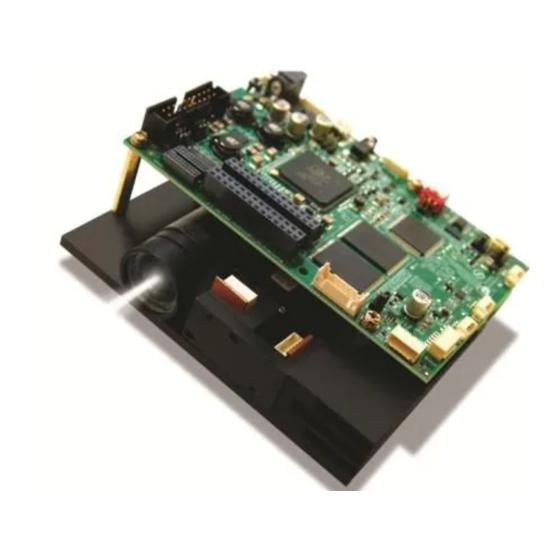
This flash programming guide provides instructions on how to create a JTAG cable and use the flash
programming tool to install the DLPR350 firmware on the DLP LightCrafter 4500.
......................................................................................................................
1
2
3
4
5
1
2
3
4
5
6
7
8
9
10
11
12
13
14
15
16
17
1
Required Pin Connections
Trademarks
LightCrafter is a trademark of Texas Instruments.
DLP is a registered trademark of Texas Instruments.
FTDI Chip is a registered trademark of Future Technology Devices International Ltd.
Windows, Visual C++ are registered trademarks of Microsoft Corporation.
Molex is a registered trademark of Molex.
DLPU017B - March 2014 - Revised February 2018
Submit Documentation Feedback
.........................................................................................................
...............................................................................................
............................................................................................
............................................................................................................
List of Figures
..............................................................................
.......................................................................................
................................................................................
...........................................................................
List of Tables
..................................................................................................
Copyright © 2014-2018, Texas Instruments Incorporated
DLPU017B - March 2014 - Revised February 2018
Contents
............................................................................
............................................................................
...............................................................
.................................................................
.........................................................................
.....................................................................
...............................................................
.....................................................................
.....................................................................
..............................................................
................................................
.....................................................................
......................................................
DLP
®
LightCrafter™ 4500 Flash Programming Guide
Programmer's Guide
2
2
3
4
18
3
4
4
5
5
6
7
8
9
10
11
12
13
14
15
16
17
3
1
Advertisement
Table of Contents

Related Manuals for Texas Instruments DLP LightCrafter 4500


Summary of Contents for Texas Instruments DLP LightCrafter 4500
-
Page 1: Table Of Contents
DLPU017B – March 2014 – Revised February 2018 ® LightCrafter™ 4500 Flash Programming Guide This flash programming guide provides instructions on how to create a JTAG cable and use the flash programming tool to install the DLPR350 firmware on the DLP LightCrafter 4500. Contents ........................Overview ...................... -
Page 2: Overview
When using the DLP LightCrafter 4500 flash programming tool, the user must have a communication link established between the DLP LightCrafter 4500 and the computer running the tool. This allows the user to read and write to the flash memory from the computer. This connection is established through the JTAG cable created following this guide. -
Page 3: Jtag Boundary Scan Cable
JTAG Boundary Scan Cable The UM232H USB-to-serial adapter must be connected to the JTAG port on the DLP LightCrafter 4500. Connecting the two devices requires the use of a Molex 51021-0600 connector. The user can either directly connect the header pins on the UM232H to the cable or create a board to host the UM232H. The... -
Page 4: Flash Programming Procedure
Flash Programming Procedure www.ti.com Flash Programming Procedure Populate J30 with a 2-mm jumper on the DLP LightCrafter 4500, as shown in Figure 2 Figure Figure 2. J30 Location on the DLP LightCrafter 4500 Figure 3. J30 Populated on the DLP LightCrafter 4500 ®... -
Page 5: Power Supply Connected To The Dlp Lightcrafter 4500
Figure 4. Power Supply Connected to the DLP LightCrafter 4500 Connect the JTAG cable to J25, located on the bottom side of the DLP LightCrafter 4500 board. Connect the UM232H to the computer with an appropriate USB cable, as shown in Figure Figure 5. -
Page 6: Jtag Flash Programmer First Run
6. Ignore any error messages about a missing board file for now. Figure 6. JTAG Flash Programmer First Run ® LightCrafter™ 4500 Flash Programming Guide DLPU017B – March 2014 – Revised February 2018 Submit Documentation Feedback Copyright © 2014–2018, Texas Instruments Incorporated... -
Page 7: Board File Selection In Flash Programmer Tool
Browse button and the selected board file path. Figure 7. Board File Selection in Flash Programmer Tool DLPU017B – March 2014 – Revised February 2018 ® LightCrafter™ 4500 Flash Programming Guide Submit Documentation Feedback Copyright © 2014–2018, Texas Instruments Incorporated... -
Page 8: Firmware File Selection In Flash Programmer Tool
Flash Programming Procedure www.ti.com Click the Browse button next to the flash image path. Select the flash image called DLPR350PROM_v****.bin that installed in the DLP LightCrafter 4500 firmware installation folder. Figure 8 shows the button and path. NOTE: The third box (shown in Figure 8) does not need to be populated. -
Page 9: Firmware File Size Selection In Flash Programmer Tool
Set the size of the image to 0x0020000, as in Figure Figure 9. Firmware File Size Selection in Flash Programmer Tool DLPU017B – March 2014 – Revised February 2018 ® LightCrafter™ 4500 Flash Programming Guide Submit Documentation Feedback Copyright © 2014–2018, Texas Instruments Incorporated... -
Page 10: Jtag Chain Detection In Flash Programmer Tool
Click the Detect Chain button in the upper left-hand corner of the tool. The Detect Chain button is indicated with a red box in Figure Figure 10. JTAG Chain Detection in Flash Programmer Tool ® LightCrafter™ 4500 Flash Programming Guide DLPU017B – March 2014 – Revised February 2018 Submit Documentation Feedback Copyright © 2014–2018, Texas Instruments Incorporated... -
Page 11: Erase Button In Flash Programmer Tool
Click the Erase button on the toolbar (see Figure 11). Figure 11. Erase Button in Flash Programmer Tool DLPU017B – March 2014 – Revised February 2018 ® LightCrafter™ 4500 Flash Programming Guide Submit Documentation Feedback Copyright © 2014–2018, Texas Instruments Incorporated... -
Page 12: Flash Memory Block Selection And Erase Button
NOTE: Erasing the flash memory can take a full minute. Figure 12. Flash Memory Block Selection and Erase Button ® LightCrafter™ 4500 Flash Programming Guide DLPU017B – March 2014 – Revised February 2018 Submit Documentation Feedback Copyright © 2014–2018, Texas Instruments Incorporated... -
Page 13: Flash Memory Block Erase Completed And Exit Button
Flash Programming Procedure www.ti.com Figure 13. Flash Memory Block Erase Completed and Exit Button DLPU017B – March 2014 – Revised February 2018 ® LightCrafter™ 4500 Flash Programming Guide Submit Documentation Feedback Copyright © 2014–2018, Texas Instruments Incorporated... -
Page 14: Program Button In Flash Programming Tool
Click the Program button on the toolbar (see Figure 14). Figure 14. Program Button in Flash Programming Tool ® LightCrafter™ 4500 Flash Programming Guide DLPU017B – March 2014 – Revised February 2018 Submit Documentation Feedback Copyright © 2014–2018, Texas Instruments Incorporated... -
Page 15: Power And Jtag Cable Removed From The Dlp Lightcrafter 4500
After the flash programmer tool displays the operation is 100% complete, disconnect the JTAG cable, remove the jumper from J30, and disconnect the power supply from the DLP LightCrafter 4500, as shown Figure Figure 15. Power and JTAG Cable Removed from the DLP LightCrafter 4500 Connect the LightCrafter 4500 to a PC loaded with the LightCrafter 4500 GUI via USB. -
Page 16: Lightcrafter 4500 Gui Firmware Upload Window
Flash Programming Procedure www.ti.com Open the DLP LightCrafter 4500 GUI and wait for the device to connect. If the device does not connect restart at Section 4. After the device is connected click the Image/Firmware tab, then click the Firmware Upload tab. -
Page 17: Starting The Lightcrafter 4500 Firmware File Upload Process
The GUI will upload the entire firmware image to the LightCrafter 4500 through the USB port. When the process is completed, the LightCrafter will automatically be reset. The DLP LightCrafter 4500 now contains the DLPR350 firmware distribution. Verify proper operation of the projector with the GUI. If the device does not boot up properly, restart at... -
Page 18: Troubleshooting
JTAG cable is connected to the JTAG boundary scan port J25 on the underside of the target board. • Problem: The DLP LightCrafter 4500 does not display the splash screen after the flash is complete. Solution: Ensure the 2-mm jumper has been removed from J30. Cycle board power and verify fan operation. - Page 19 Added step to connect LightCrafter 4500 to PC ..........• Added step to upload entire DLPR350 PROM through LightCrafter 4500 GUI DLPU017B – March 2014 – Revised February 2018 Revision History Submit Documentation Feedback Copyright © 2014–2018, Texas Instruments Incorporated...
- Page 20 IMPORTANT NOTICE FOR TI DESIGN INFORMATION AND RESOURCES Texas Instruments Incorporated (‘TI”) technical, application or other design advice, services or information, including, but not limited to, reference designs and materials relating to evaluation modules, (collectively, “TI Resources”) are intended to assist designers who are developing applications that incorporate TI products;...
Need help?
Do you have a question about the DLP LightCrafter 4500 and is the answer not in the manual?
Questions and answers